Week- 5 - Solid meshing
OBJECTIVE:
To mesh the given rear view mirror in both 2D and 3Delements , and checking the model for geometrical errors and fixing them. and to ensure the generated mesh follows the given quality criteria.
Solid Elements
requirement: Tet Collapse should be a maximum of 0.2 for all solid elements.
Shell Elements
requirement: Min and max length should not fail
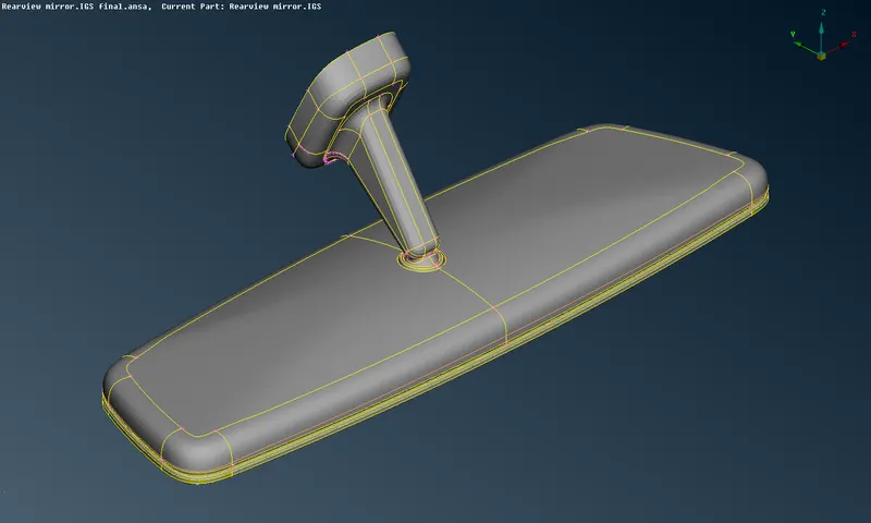
CAD MODEL IMAGE
PROCEDURE
1. To fix the geometry the topo tool to take care of all the single cons and to ensure there are no free edges. It can be accessed via Faces > Topo in the topo module. All the cons are selected and the algorithm takes care of all the single cons.
2. After that, as is the norm with meshing on ANSA and before we carry out any other actions, we need to carry out a geometry check and fix all errors. That is done via Checks > Geometry where we can check of certain defects that can be selected from the menu and the algorithm looks for said defects. After detection, we can select all the defects and right-click > fix to fix them.
3. After orienting the model, using the Faces > Orient tool, we can go ahead and work on meshing the surface of the model. As part of this, we need to assign the mesh properties and quality parameters. We need to assign the target length. To do this, we can go to the mesh module and Perimeters > Length. This lets us adjust the target length and effectively, the resolution of the cons to be finer. As is required, the length would be 1mm.In the case of quality criteria, we will need to access the solids tab as well to input the tet collapse criteria.
4. Since some regions might fail for minimum tool, they can be modified by taking care of the boundaries (cons). The cut tool can be used to suppress some of these cons and in other regions, we can create cuts. All this to ensure the mesh generated would be favourable and does not fail for any of the criteria. 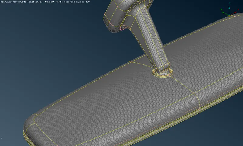
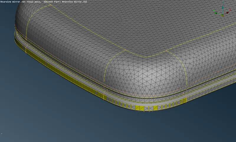
5. Now we can go ahead and mesh the component. The spot mesh tool is used (Mesh Generation > Spot Mesh). For regions that are flat and not as complicated, the tria mesh can be used. The option to switch to tria is in the bottom left options section after selecting the spot mesh tool.
In the more complex regions (such as fillets and hemmings), we can make use of the ortho tria tool, which is another mesh type available from the same set of options.
6. After each mesh iteration, we will need to reconstruct the mesh using Shell Mesh > Reconstruction. For this to be effective, the neighbouring mesh is selected as well. This ensures the reconstructed mesh is of good quality and flow. The mesh type will need to be changed for this tool as well from the set of options that appear in the same region as the spot mesh tool (when the reconstruct tool is activated).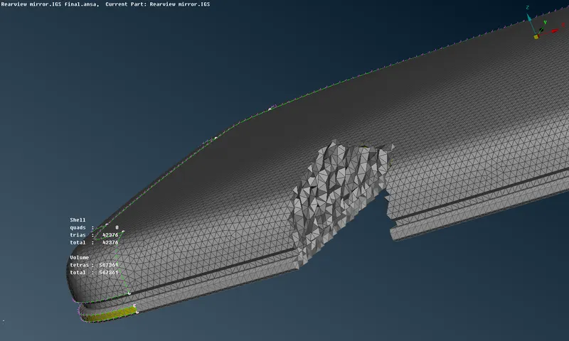
7. After meshing all regions (and ensuring there are no off elements - should be taken care of already through reconstruction), we can proceed to the next step of assigning volumes manually to each set of closed-shell elements. This is done by using Volumes > Define > Manual and then selecting the regions that comprise a particular volume. In this case, the PID selection tool from the bottom left toolbar would be useful in selecting the entire volume since the property ID has already been assigned for certain regions.
8. click each volume and remesh them using either one of the tetra rapid or tetra FEM algorithms. Doing so generates the solid mesh elements within each volume.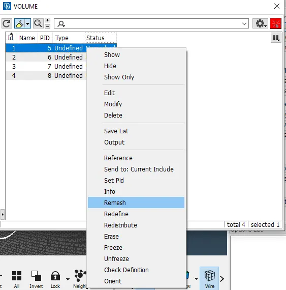
9. Next we need to check the solid elements to see if any fail for the tet collapse criteria by switching to hidden mode. There are two ways to fix tet collapse failures. One is by using the Fix Quality tool from the volume mesh module (Improve > Fix Quality). This is an algorithm that works on failing elements. But it may result in protrusions or depressions on an otherwise flat surface.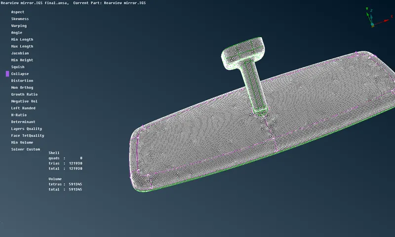
To avoid this, the MV free tool can be used (Grids > MV Free) which is available in the mesh module. This lets us manually drag particular nodes of the failing element such that the height of the tetra element can be increased. This helps pass the tet collapse criteria. Understandably, to avoid the same problem as in the Fix Quality tool, care should be taken to not move nodes that are on the surface of the component but the ones that are below the surface.
LEARNING OUTCOMES
1. Learnt some tools related to solid meshing.
2. Learnt to assign volumes for closed shell element regions.
3. Learnt to fix tet collapse failures.
4. Familiarized with the ortho tria and tria mesh types through the spot mesh tool.
RESULT
The given component was geometrically fixed and meshed as per the given requirements and criteria and the generated shell mesh was used to create the solid mesh. Quality and flow were achieved and care was taken to ensure there were no deformations of any kind on the surface.