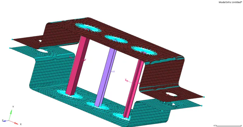
Week 4-1D Element Creation Challenge
1.
OBJECTIVE:
To mesh the given component with size of 5 units and to create 1D elements to the given component with the given cross-section and DOF's.
PROCEDURE:
- Import the given geometry from file -> import(IGES file).
- After importing, the midsurface should be extracted. To extract midsurface, click on midsurface -> auto extraction.
- Now select the surface and click on extract (Here, offset is used in extraction options inorder to get the smooth surface edges where the mesh flow will be proper).
- Tools -> organise is used to assign the midsurface to a particular component.
- 2D mesh is created for the midsurface from 2d -> automesh(element size 5).
- Washersplit from quickedit is used for the proper meshflow and the offset added as 5
- Click on create -> material to create material add Material type as steel.
- To create rigids, click on 1D -> rigids ->create. Select the nodes and click on create.
- Similarly, to create rbe3 elements click on 1D -> rbe3 ->create.
- After creating rigid body elements, the cross-sections has to be created to the rigid elements.
- Hyperbeam is used to create cross-section i.e., hyperbeam -> standard section -> standard section type.
- To create a bar element, click on bars -> select nodes -> element type(CBAR) -> create.
- Similarly, for rod and beam elements, click on rods -> select nodes -> element type(CROD) ->create; bars -> select nodes -> element type(CBEAM) ->create.
ROD ELEMENT:
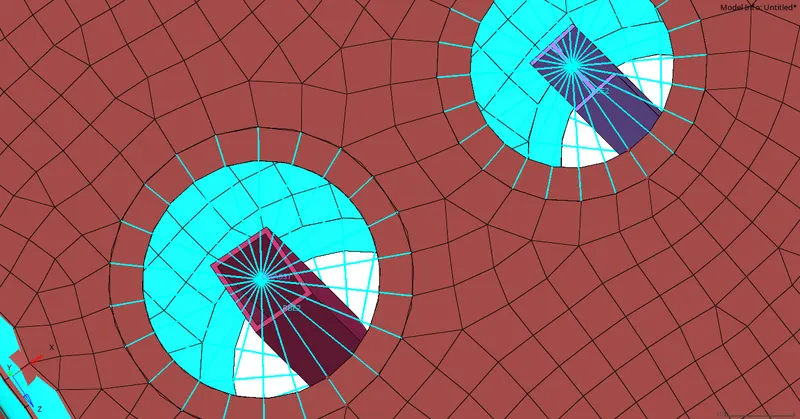
- Thinwalled box is selected as the section type, and the dimensions are given as specified(a=12mm, b=10mm, t=0.75mm).
- Here, translational DOF'S is constrained with the RBE2 link i.e.., dof1, dof2, dof3 is constrained.
BEAM ELEMENT:
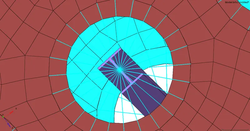
- Standard I section is selected as the section type, and the dimensions are given as specified(a=8mm, b=10mm, c=8.5mm, t1=0.75mm, t2=0.6mm, t3=0.6mm)
- Here, DOF is constrained with rbe3.
BAR ELEMENT :
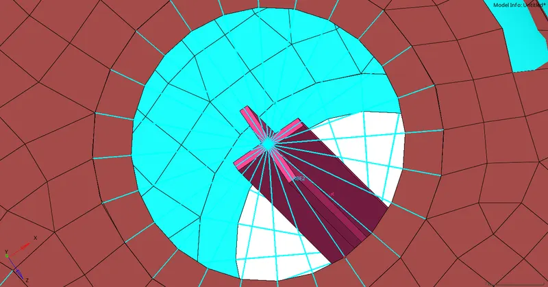
- Cross section is selected as the section type, and the dimensions are given as specified(dim1=5mm, t1=1.2mm, dim2=10mm, t2=1.2mm).
- Here, X and Y DOF'S is constrainedwith the RBE3 Link.
PROPERTY:
- Property should be assigned to the cross-sections created. Click on create -> property.
- For rod element, select the card image as PROD and assign the property.
- Similarly for BAR AND BEAM ELEMENT , select the card image as PBAR and PBEAM.
- To update the properties to the elements, click on beam -> update -> property; rods -> property -> update; bar -> property -> update.
MASS:
Mass of magnitude 10 added with the RBE2 links masses -> node select -> define mass -> create.
Join two components with spring element:
Two components is joined using a spring element from springs -> nodes -> element type (CELAS1) -> create.
FINAL MODEL IMAGE: