Week 5:- Rest Unit & Clamp Unit Design Challenge
OBJECTIVE:
To design 3 different types of power clamp units with different riser, blade, and clamp arm & to design 2 different types of rest unit for the given car panel.
ABSTRACT:
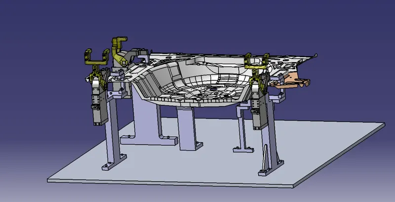
In this project, I have designed different types of power clamp units by validating a power clamp cylinder and by considering a clamping force acts at each end of the mylars and also designed different types of rest unit by considering a holding force for the given car panel. Hereby considering the fundamentals of clamp unit design I have briefly explained about the,
- Purpose of Clamp unit.
- 3-2-1 Principle achieved by clamping. Clamp plans.
- Structured design tree.
- How to validate a power clamp cylinder.
- How to calculate the clamping force acting at the end of each mylar.
- Materials, surface finish & Heat treatment used in the parts of clamp unit.
SOFTWARE USED:
- CATIA V5
DESIGN PROCEDURE:
CLAMP UNIT:
- A clamp unit is a unit designed to clamp/hold the car panel with NC blocks / Mylars / Rest by using a pneumatic cylinder. Clamp arm, finger, rest/backup, L-block, shims, Risers, Pneumatic cylinders are the typical parts of clamp unit.
- Clamping force should be considered while designing the clamp unit.
REST UNIT:
- A rest unit is used to support the car panel, Also is resists the clamping force of the finger with the help of rest mylars & thus clamp the car panel.
- The Rest unit consists of rest mylars, shim packs, riser.
- Holding force should be considered while designing a rest unit.
- Mostly to avoid excess part, to reduce the weight & reduce the cost of the fixture the rest unit is combined with the clamp unit.
- The below figure shows the combination of the clamps & rest unit which have been designed in this project by considering the basic principles of clap & rest unit design.
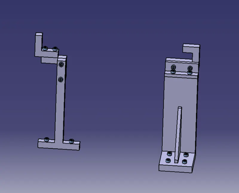
FIG: REST UNIT
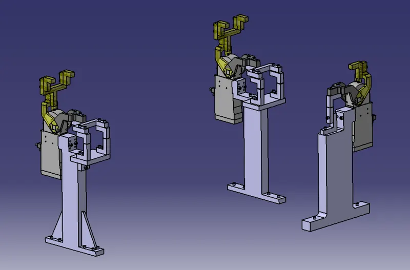
FIG: POWER CYLINDER CLAMP UNIT
TYPES OF CLAMP UNIT:
- Power Clamp unit.
- Swivel cylinder clamp unit.
In this project, I have used a power clamp unit to design.
PURPOSE OF CLAMP & REST UNIT:
- The purpose of clamping tools is to securely hold the workpiece in position without obstructing the production process. High clamping forces combined with compact dimensions are therefore the most important requirements for a clamping tool. For this reason, clamps are also equipped with mechanical transmission gear units.
(3-2-1principle) archived by clamping & resting:
- The best & most cost-effective method of part location is referred to as the 3-2-1 method. Fixtures work on of 3-2-1 principle.
- Minimum Three locators or support are placed under the work Three locators or support are placed under the workpiece. Three locators are usually positioned at the primary locating surface.
- This restricts two axil movements downward & upward and four radial movements. Together, the three locators restrict six degrees of freedom.
- As by the 3-2-1 method, introducing a minimum of 3 clamping & 3 resting blocks will restrict 6 degrees of freedom (DOF) [Two axial movements & four radial movements].
CLAMPING:
- The car panel will rest on the rest unit, Also it resists the clamping force of the finger & thus clamps the car panel.
RESTING:
- The car panel will rest on the rest unit, Also it resists the clamping force of the finger & thus clamps the car panel.
FORCES ACTS IN CLAMP & REST UNIT:
- To design a clamp unit we have considered some forces which acts in clamp unit for clamping purpose. The forces that act in clamp units are,
- Clamping force.
- Holding force.
Clamping force is not the same as holding force.
CLAMPING FORCE:
Clamping force signifies the force applied to the workpiece by the drive mechanism via the clamp arm during gripping or clamping operations.
Clamping force (Fs) = 48 x S3 = Force in newton HOLDING FORCE:
Holding force, on the other hand, denotes the maximum force, after locking the knee-lever (over-center position), that can be applied by the workpiece on the gripper/clamp arm without destroying the mechanism. Therefore, particular attention must be paid to the maximum holding force when, for example during the production process (welding, bonding), there is a possibility of distortion of the component or if the clamp arm is used as a fixed stop.
If the holding force specified in the technical details is exceeded, this will inevitably result in the destruction of the mechanism, the clamp arm, or the bearing position.
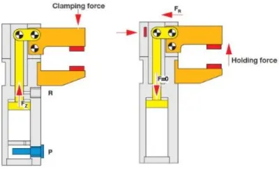
Fig: Clamping force & Holding force
DESIGN TREE:
- Structuring a design tree implies a process where all the assemblies & parts are named in a specific standard. Different customers have a different set of standards to structure a design tree.
- It is an important process that helps us to identify a specific part or assembly as to which project, tool/unit, it belongs to.
- This helps us to avoid errors during design study, manufacturing, assembly, inspection, etc.
- If the parts or assemblies are not named properly or the design tree is not structured properly, it will create confusion to understand the design & may create major possibilities of making an error.
- The naming of a fixture or a unit or a part gives the information as to which project or zone or assembly do they belong to.
- It can help us to identify the number of items of the same types or different types that are being used in the assembly.
- While start designing a fixture, the first unit will be the base unit.
- In the structure tree, all the manufacturing parts should be first and the standard parts should be at the last.
- A structure tree helps to study or understand the parts in the assemblies easily.
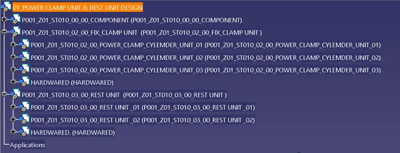
FIG: TREE STRICTER
Under each unit will contain parts of the unit as shown in the above figure.
PLP LOCATION & CLAMP PLAN:
PLP (PRINCIPLE LOCATING POINTS):
- Principle locating points are the points that are used for the accurate location of the panel's sub-assemblies to maintain the geometry of the assembly.
- There are lots of holes on the panel which is accurate due to stamping operations.
- So the PLP is defined in the drawings. The PLP holes must be very much precise.
CLAMP PLAN:
- The clamp plan provides information on the location of pins, rest units, clamp units, dumps, etc.
- It is an important input from the customer. The clamp plan/position should not be changed without the knowledge of customers.
- It gives the detail of the exact position of the clamping units by mentioning a coordinate in the particular position.
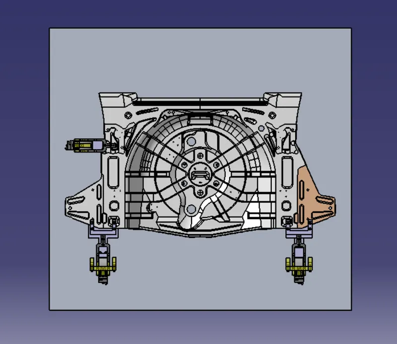
FIG: PLP & CLAMP PLAN
SELECTION OF PNEUMATIC CYLINDERS
- Single or Double acting
- Dimensional standards like ISO, VDMA, CETOP, AFNOR.
- Constructional details like – Piston rod, tie rod, square tube, Mickey mouse tube, rodless, etc.
- Force to be exerted (Bore dia)
- Distance to be moved (stroke)
- Surrounding medium (special material of construction/type of seals)
- Air pressure available.
- Cushioned / Non cushioned.
- Ambient temperature for selection of seal material.
- Speed of actuation
- Position detection (Reed switch type)
- Mountings
- Stop tube length for long-stroke cylinders.
SPECIFICATION OF PNEUMATIC CYLINDERS
- Cylinder thrust.
- Air consumption.
- Piston velocity.
- Type of mounting.
- Couplings
FORMULA & CALCULATION:
HOW TO FIND OUT THE OUT TREACH OF CLAMP ARM?
By measuring the distance between the pivot center of the cylinder and the center of clamping mylars we can get the outreach of the clamp arm as shown below figure.
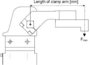
Fig: Length of clamp arm
Below given details are the outreach of the clamp arm taken from the respected clamp unit used in this project,
- P001_Z01_ST010_02_00_POWER_CLAMP_CYLEMDER_UNIT_01 – an outreach of the clamp arm is 120mm.
- P001_Z01_ST010_02_00_POWER_CLAMP_CYLEMDER_UNIT_02 – an outreach of the clamp arm is 205mm.
- P001_Z01_ST010_02_00_POWER_CLAMP_CYLEMDER_UNIT_03 – an outreach of the clamp arm is 205mm.
After choosing the sheet thickness and the outreach as shown above, now we can refer to the graph shown below for selecting the power clamp cylinder as per our requirements.
By relating the sheet thickness & outreach from the above graph, we can find the bore capacity of clamp cylinders. Based on the bore capacity the cylinders will be selected for the clamp unit.
I have compared my clamp unit design with the above graph, as per the relation between the graph & the design I have found the bore capacity of cylinders which is been used to design the clamp unit.
General procedure to choosing a clamp:
A. Definition of the required clamping force of the particular component points:
Sheet thickness (S)
Quality of metal sheet (e,g. ST quality)
Clamping force (Fs) = 48 x S3 = Force in Newton
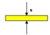
Fig: Shows the Sheet thickness (S)
In this project, we consider the sheet thickness as 1 mm so analytically the clamping force will be,
Clamping force (Fs) = 48 x 3 = 144 = Force in Newton
Clamping force (Fs) = 144 N (Analytically)
B. Determination of the clamping torque required “Ms”: Outreach component/clamping arm length “l”
Clmaping torque (Ms) = Fs x l
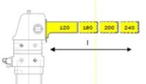
FigShows the length of the Clamp arm (l)
In this project,
- For P001_Z01_ST010_02_00_POWER_CLAMP_CYLEMDER_UNIT_01, Ms= Fs x l = 144 x 120 = 17280 Nmm =17.280 Nm = 17 Nm.
Clamping Torque at P001_Z01_ST010_02_00_POWER_CLAMP_CYLEMDER_UNIT_01 is 17 Nm.
- For P001_Z01_ST010_02_00_POWER_CLAMP_CYLEMDER_UNIT_02, Ms= Fs x l = 144 x 205 = 29520 Nmm = 29.520 Nm = 30 Nm.
Clamping Torque at P001_Z01_ST010_02_00_POWER_CLAMP_CYLEMDER_UNIT_02 is 30 Nm.
- For P001_Z01_ST010_02_00_POWER_CLAMP_CYLEMDER_UNIT_01, Ms= Fs x l = 144 x 205 = 29520 Nmm = 29.520 Nm = 30 Nm.
Clamping Torque at P001_Z01_ST010_02_00_POWER_CLAMP_CYLEMDER_UNIT_02 is 30 Nm.
Holding force depending on load offset:
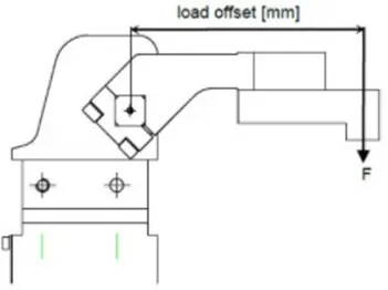
Fig: Load offset
MATERIAL USED:
In general, the materials used for Mylars, Clamp arm, shims, shim block, blades & risers are:
- Mylars: UHMW, Nylon66, PP, Teflon (Polytetrafluroehylene (PTFE)). Materials of clamp block and rest block to be decided as per the A class panel or B
- Clamp Arm: SAE 4140 or SAE 1045.
- Shims/spacer: S.A.E. 1010 CRS FULL HARD, COLD ROLLED STRIP STEEL S.A.E. 1010 FULL HARD, S.A.E. 1020 HRS, etc.
- shim block: STEEL ASTM A- 36, NM stainless, STEEL ASTM A-36, SS type 3030 or 304,
- Blade: STEEL ASTM A-36,
- Riser: STEEL ASTM A- 36,
HARDNESS:
In general, the hardness of the materials for pins, pin retainers, shims, shim block, blades & risers is 55 – 60 HRC to a depth of 0.5 -0.7mm after grinding.
SURFACE FINISH:
In general, the hardness of material for Mylars, Clamp arm, shims, shims block, blades & risers are:
- Clamp arm: Munsell No.3.75YR6/14 safety orange
- shims/spacer: BLACK OXIDE FINISH (SURFACE TO BE FLATE PARALLEL TO WITHIN 0.015 T.I.R.
- Riser: SURFACES TO BE FLAT, PARALLEL & PERPENDICULAR TO WITHIN 0.015 T.I.R.
UNIQUE PARTS OF A CLAMP & REST UNIT:
Finger: The finger is an NC block, which is mounted on the clamp arm of the cylinder. And will press the car panel towards the rest, so it holds the car panel.
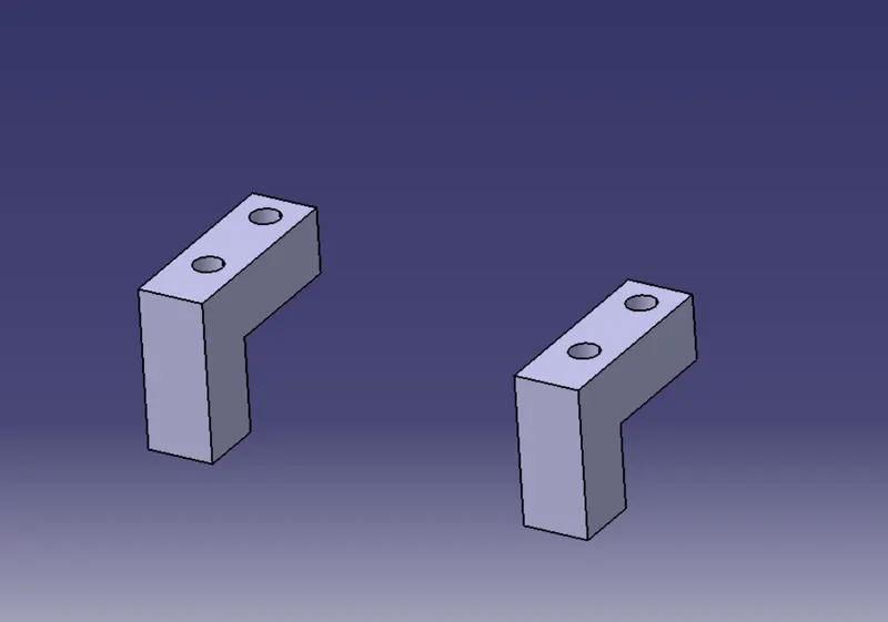
Fig: Clamping Mylar / Finger used in this projects
REST: A rest is an NC block, which is fixed to the unit to support the car panel, Also it resists the clamping force of the finger & thus clamp the car panel.
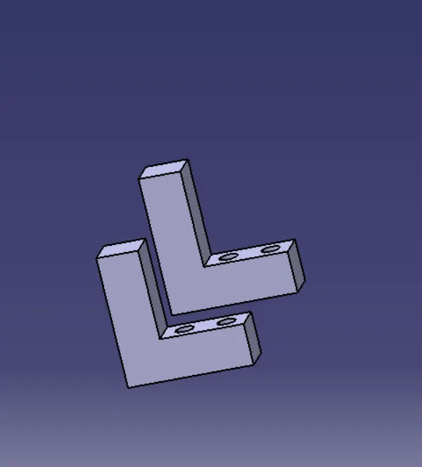
Fig:Resting mylar / Rest
CLAMP ARM: The clamp arm is a part to which all the moveable parts are fixed. In general, clamp arms are available based on the position of the arm.
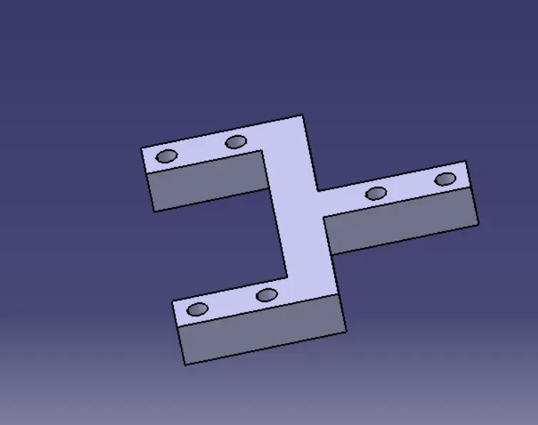
Fig: Clamp arm
Clamp Cylinder: It is a Pneumatic cylinder device that works with pressurized air (5 bar pressure is standardly used to clamp automobile parts). The clamping cylinder is used to open & close the parts fixed to the clamp arm.
Clamp cylinders are bought out Some of the manufacturers are Tunkers, Zytran, Destaco, Festa, Steel smith.
- Clamp cylinders are generally 40, 50, 63, & 80 bore capacity ( Have to choose as per sheet thickness Vs outreach graph).
- Open up to 135 degrees for horizontal clamp
- Open up to 105 degrees for vertical clamp mounting.
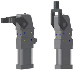
Fig: Clamp pneumatic cylinders
I have used Vario series clamp cylinders of 50 bore capacity by referring to the sheet thickness vs outreach graph.
V_50_1_BR3_A40_T12_TUENKERS: Vario clamp with toggle joint mechanism and continuously adjustable opening angle, over-center-lock, enclosed aluminum housing, oval-shaped cylinder in the size 50, 63, 80 forked clamping arm, the standard hole pattern for adapting contour blocks, continuously adjustable opening angle 5 – 135, optional: weld immune inductive sensing of closed and opened position (T12).
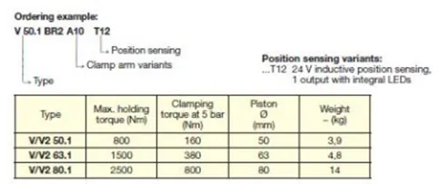
Fig: Clamp cylinders specification for ordering
PICTURES OF THE PROJECT IN DIFFERENT VIEWS
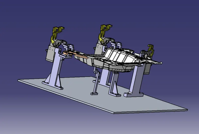
Fig: Panel with all Element
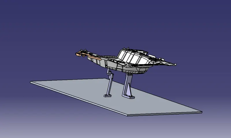
Fig: Panel with Rest Unit
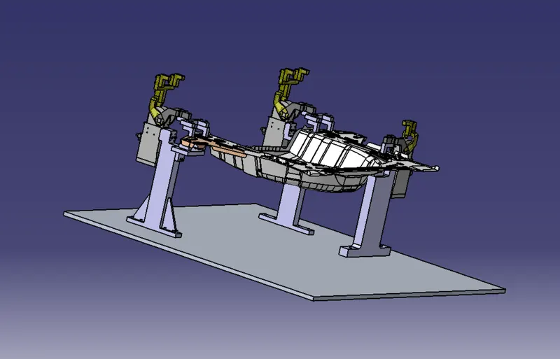
Fig: Panel with Clamp unit
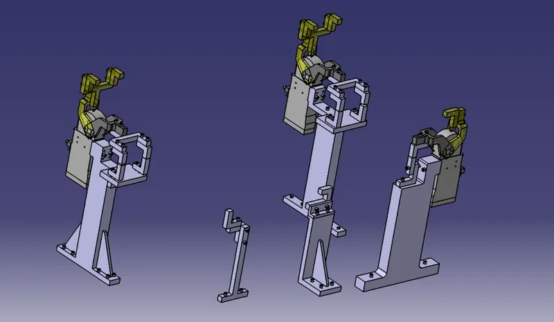
Fig: Rest Unit & Clamp Unit without panel
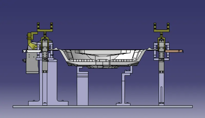
Fig: Front View
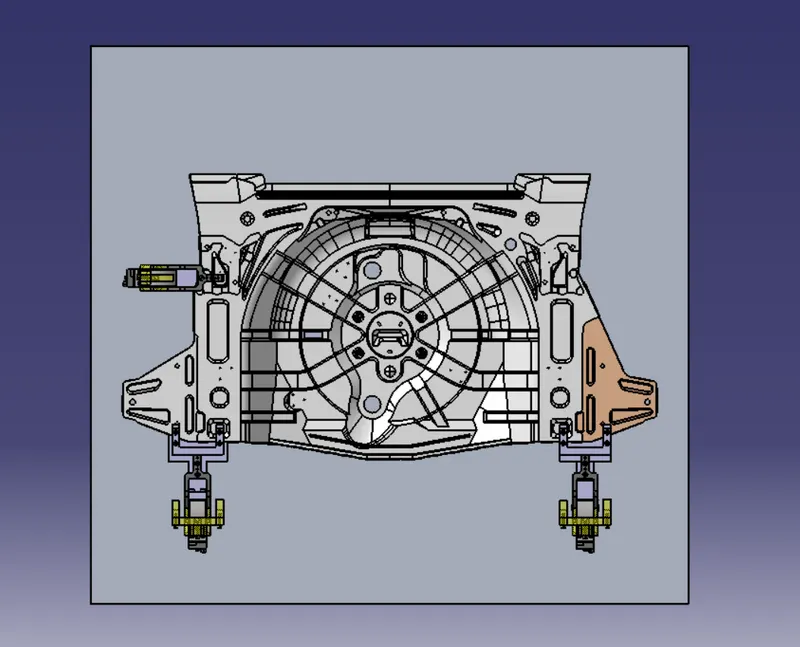
Fig: Top View
CONCLUSION:
Hence as per objective, the 3 different types of power clamp unit by validating a power clamp cylinder and by considering clamping forces acts at each end of the mylars & 3 different types of rest unit by considering holding force has been designed. Also, the materials, surface finish & heat treatment used in the parts of the clamp unit, the purpose of the clamp unit, (3-2-14 principle) achieved by clamping, PLP points (Principle Locating Points) & Clamp plans are briefly explained in detail.