Week - 5 - Modelling Spotwelds
Aim: The main objective of this challenge is to create the different spotwelds between the given parts and to run the simulation in the ls-prepost and aslo check difference between the spotwelds.
compare the results for the spotwelds made by beam and solid elements.and unit system followed by this assignment is gm mm ms.
Explanation:
procedure for creating the beam spotweld:
- imported the keyword file in ls-prepost.
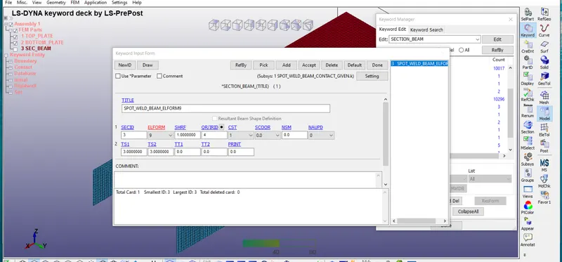
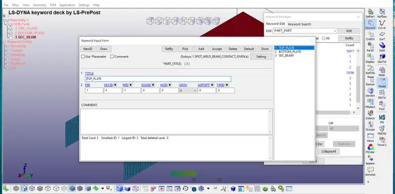
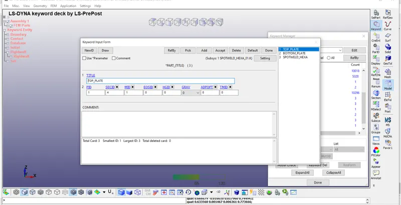
- create the section for both shell and beam elements.
ELFORM2 for shell elements.
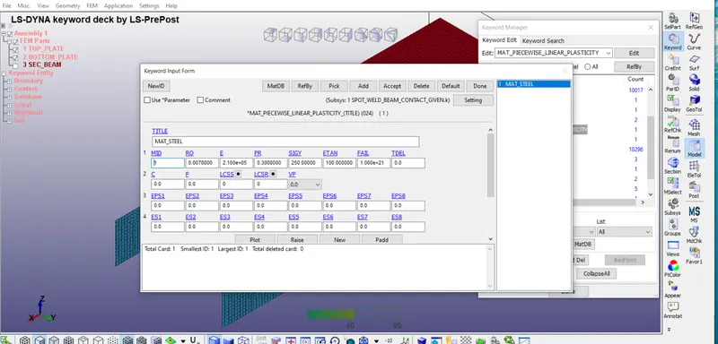
ELFORM9 for beam elemets. - create the Materials for both shell and beam elements
MAT24-piecewise_linear_plasticity for shell elements.
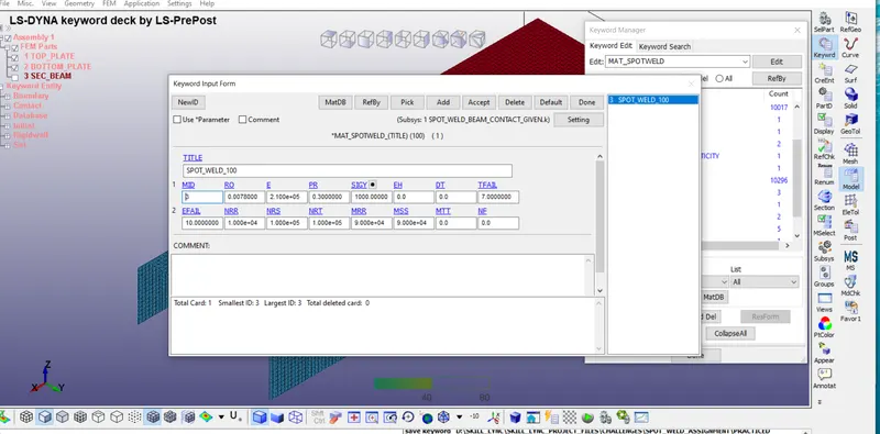
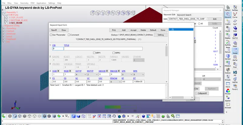
MAT100-spot_weld for beam elements. - create the contact for beam elements and shell elements.
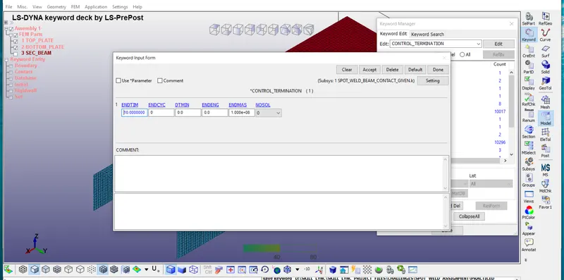
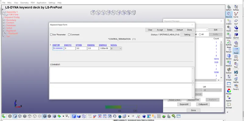
TIED_SHELL_EDGE_TO_SURFACE contact used. here we are giving slave nodes as spotwelds and master segment as shell elements. - create the Termination time i.e's ENDTIME is 10ms.
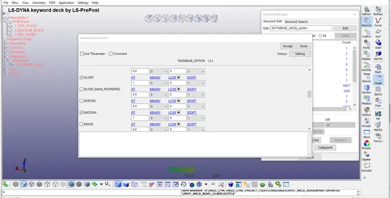
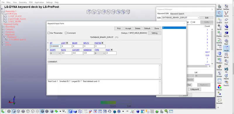
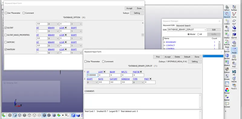
- create the output cards in *DATABASE which are
Binary_D3plot
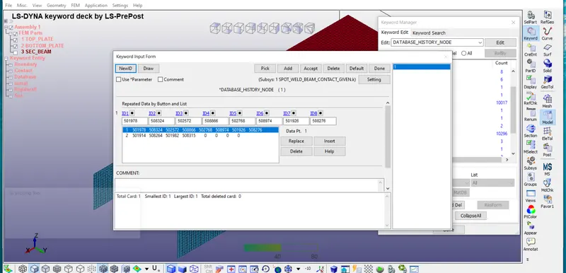
History_node
Extent_Binary
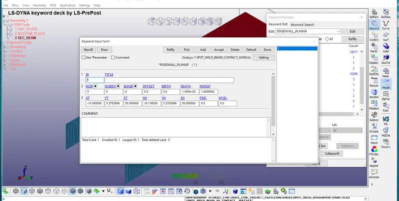
and also given GLSTAT,MATSUM,SWFORCE,SLEOUT,NODEOUT,RCFORCE are given in ASCII option. - create the Rigid wall planar *RIGID_WALL
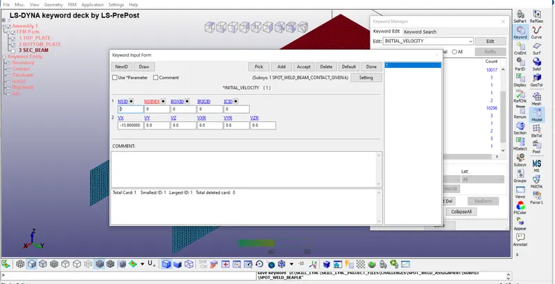
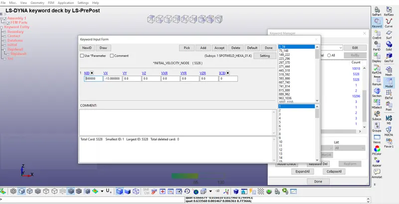
planar wall is created 15mm away from the shell parts in the direction of X-axis. - create the initial velocity in the direction of x-axis the velocity value is 13.8mm/ms.
- craete the *Boundary_spc_set at the end of the shell elements.and fix in all directions apart from the x-axis.
Animation plots :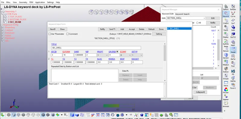
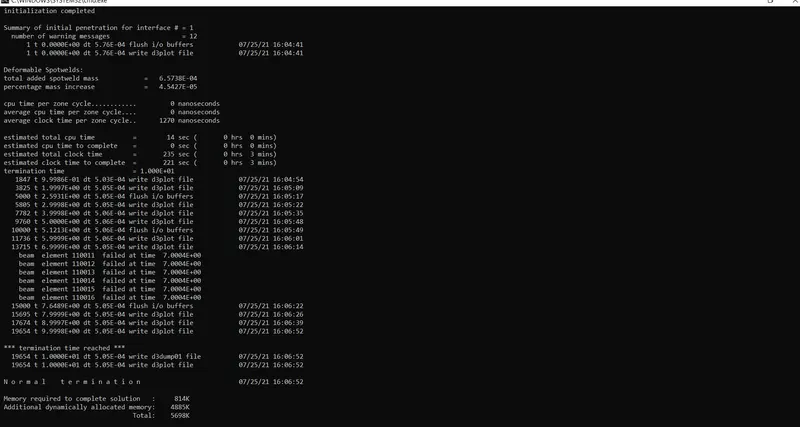
Results:
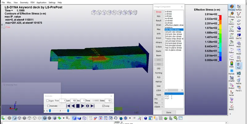
The vonmises stress are ploted below.
the maximum vonmises_stress value is 2.814e2
and the minimum vonmises_stess value is 0.00e0
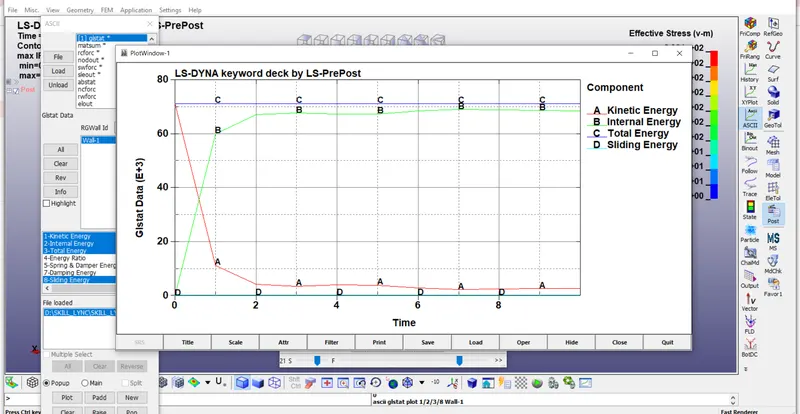
Glstat i.e global energies like kinetic,inernal,total,sliding energies are ploted below.
in results for spotweld we will check the SW_force output results.in this Axial force, shear force and resultant forces are ploted below.
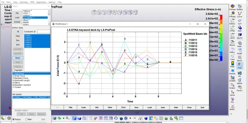
by observing the above graph here for node no D-110014 having the more axial force acting on the beam i.e 2200N
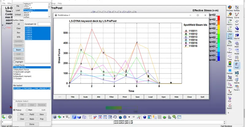
by observing the above graph here the node no A-110011 having the more shear force acting on the beam i.e 5400N.
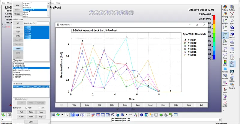
resultant forces are acting on the beam is shown in the above graph.
Procedure for creating solid element spotweld:
- create the section for both shell and solid elements.
ELFORM2 for shell elements.
ELFORM1 for solid elemets. - create the Materials for both shell and solid elements
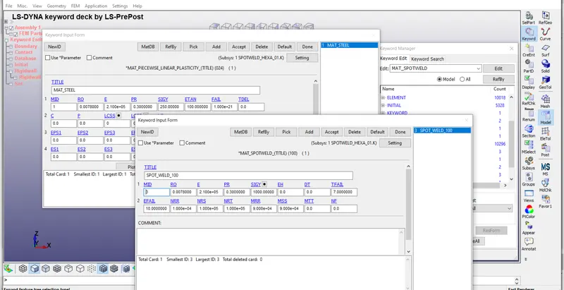
MAT24-Piecewise_Linear_Plasticity for shell elements.
MAT100-spot_weld for solid elements. - create the contact for solid elements and shell elements.
TIED_SHELL_EDGE_TO_SURFACE contact used. here we are giving slave nodes as spotwelds and master segment as shell elements. - create the Termination time i.e's ENDTIME is 10ms.
- create the output cards in *DATABASE which are
Binary_D3plot
History_node
Extent_Binary
and also given GLSTAT,MATSUM,SWFORCE,SLEOUT,NODEOUT,RCFORCE are given in ASCII option. - create the Rigid wall planar in *RIGID_WALL
planar wall is created 15mm away from the shell parts in the direction of X-axis. - create the initial velocity in the direction of x-axis the velocity value is 13.8mm/ms.
- craete the *Boundary_spc_set at the end of the shell elements.and fix in all directions apart from the x-axis.
Animation plots: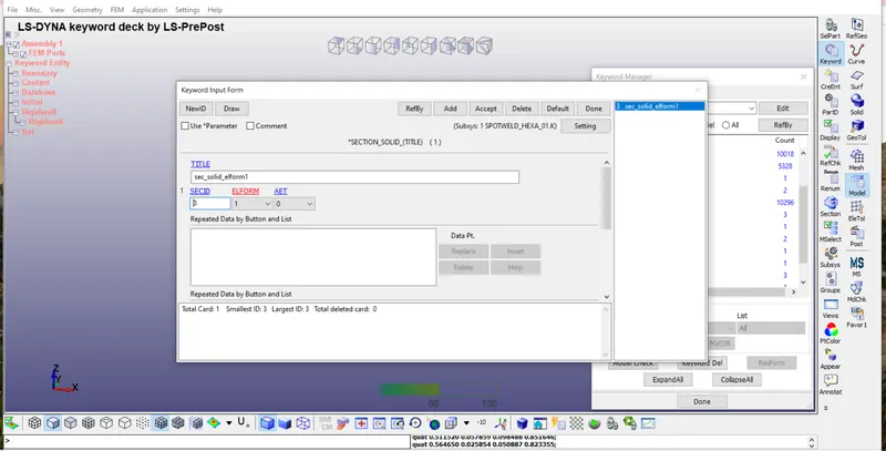
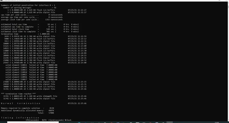
Results: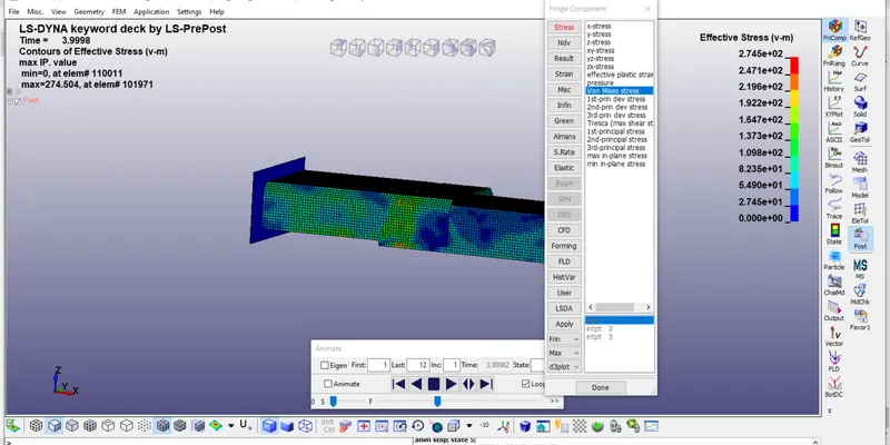
in the above results vonmises stress max value is 2.745e2
and min value is 0.00e0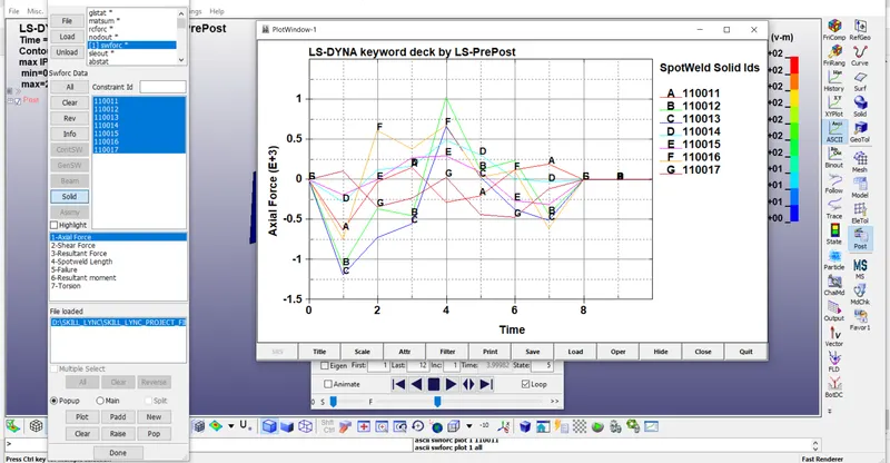
in the above graph the Node no B-110012 having more axial force when compare to the other nodes. i.e 1000N
in the above graph the Node no C-110013 having more shear force when compare to the other nodes.i.e 1.6e3N.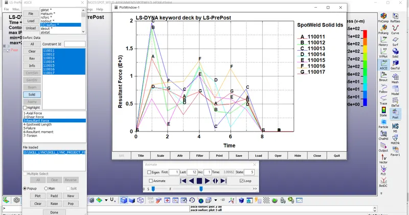
Conclusion:
finally we can conclude that we used spotweld technique for both beam and solid elements. in this spotwelds beam element receives more effective stress than solid elements.