Week - 5 - Modelling Spotwelds
OBJECTIVE:
To create spotweld connections for the given model using the beam and Hexa element in the LS-Dyna.
PROCEDURE:
- Import the given model to the ls-dyna which is in the keyword format and it is meshed
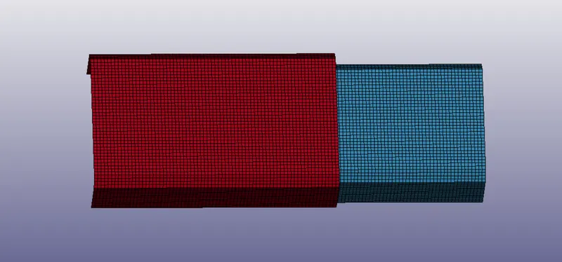
- Now we can see the two different thin plates which are together but do not have connections.
- Here we need to create a spot weld connection for the model. To do that first we need to create the required elements between the plates and then we need to give spotweld material to that element.
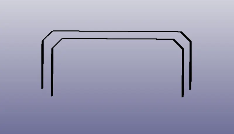
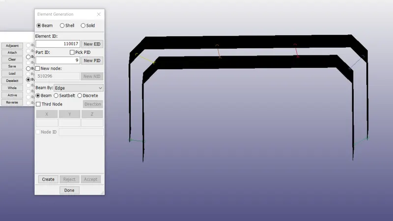
- First, we are following the beam type spotweld, to create a beam go to the element and mesh deck in that select the element generation and with help of two nodes, we can create a beam element.
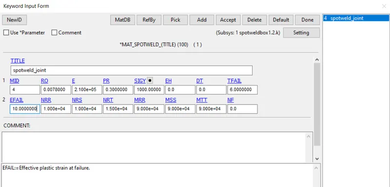
- To turn the beam element into a spotweld we need a material card and a connection card, so go to the material card and select the mat 100 spotweld card and give the steel properties to it and also mention the failure criteria for the spotweld.
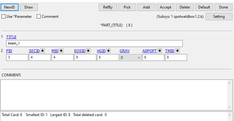
- Create a section to the beam elements which is beam keyword and mention the beam card id and material card id in the part section.
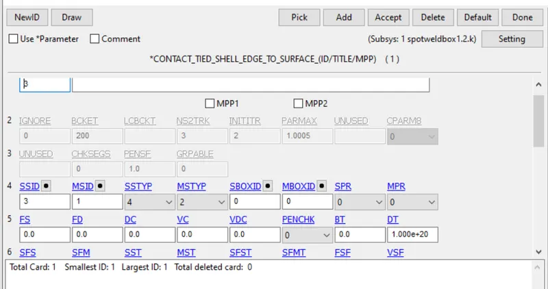
- To create a connection go to the contact keyword and select the tied shell edge to the surface and here we need to create a master and slave id for the contact.
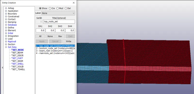
- To create them go to the create entity and select the settings option and create a slave set using the beam node-set id and master set using the entire part set id and give this id number in the contact keyword and accept it.
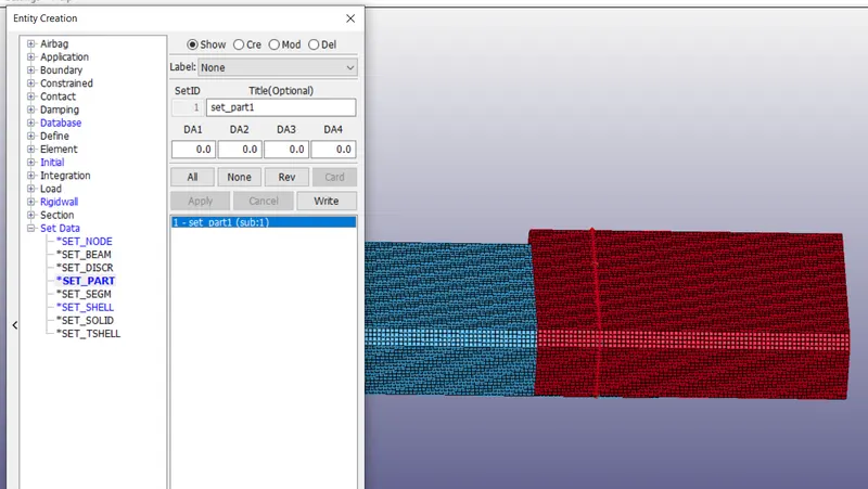
- Now we have created a complete spotweld connection for the given model but we need to create a crash test for the model using the rigid wall.
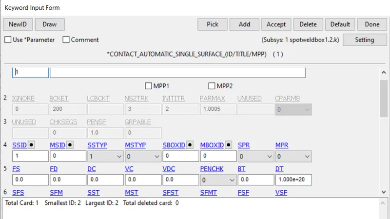
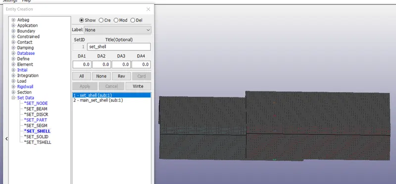
- To create the crash test first we need to have a contact connected to the rigid wall, to create that go to the contact keyword and select an automatic single surface.
- Here we need to give slave set id using entire shells of the model, create the shell set using the settings option and give the id number in the contact keyword and accept it.
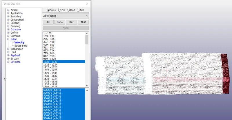
- To move the model we need to have a velocity card, to create got to create an entity and select the velocity card and select the entire elements of the model and specify the direction of the model with speed 13.888 mm/ms, and accept it.
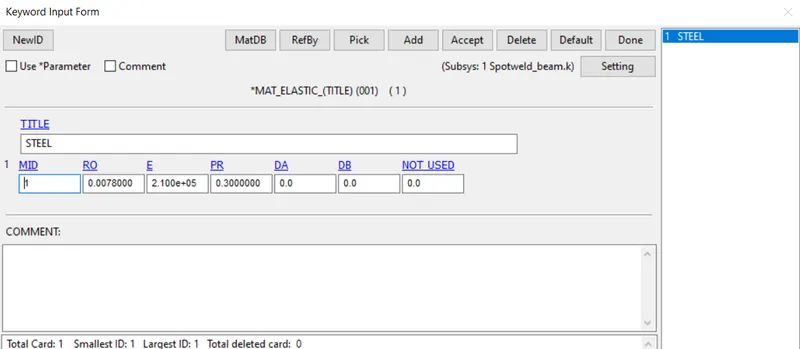
- Now create a material card for the model using the mat 001 elastic cards and give the steel properties to the card.
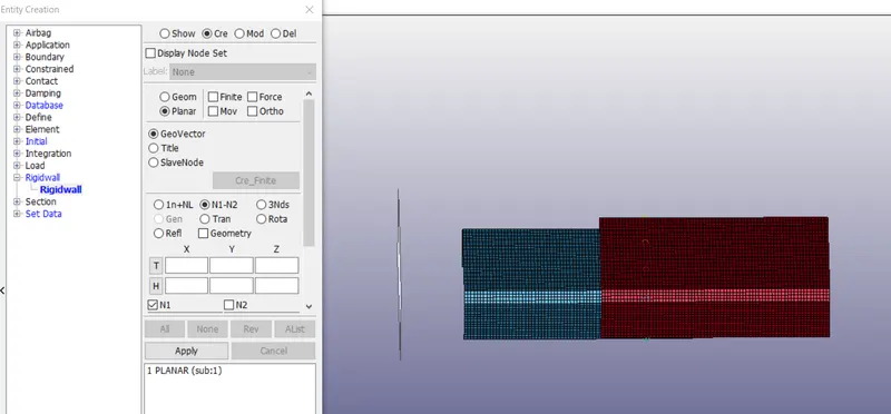
- Now create a rigid wall using the create entity option and select the rigid wall planar and select the N1 and N2 nodes and it shows the rigid wall and accepts it.
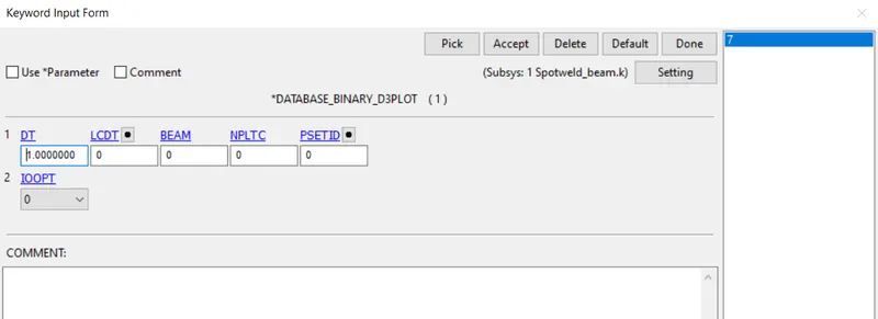
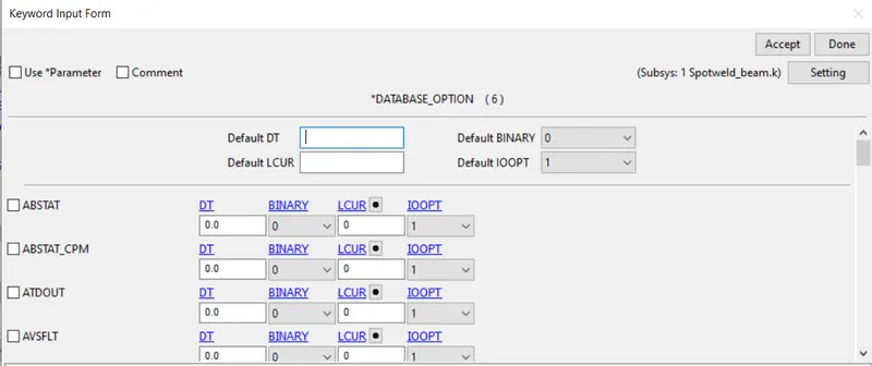
- Now a crash test model is completed but gets the results we need to give the database keywords like ASCII, Binary d3plot, History node-set, and cross-section. Give the control termination time as 6ms.
- Now go to the ls manager and run the keyword file and it gives normal termination it means our crash test model is correct.
- To extract the results again open the new tab in ls prepost and open the file of d3plot and here we can see all the results.
- Now we are going to use a solid or Hexa element for the spotweld instead of a beam.
- To create a solid element go to the element generation deck and select the element editing and create the Hexa or solid element by selecting the two shell elements between the plates, like we will create the six hexa elements.
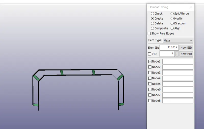
- For this also we need to create a contact keyword. To create a go-to contact keyword manager and for the Hexa element, we will select the spotweld contact.
- To this also we need to create a slave set id and master set id as we did for the beam spotweld method and give the id for the spotweld contact and accept it.
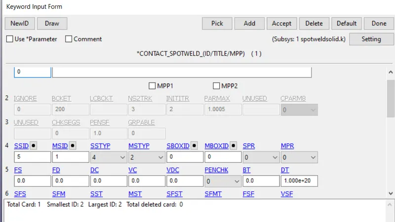
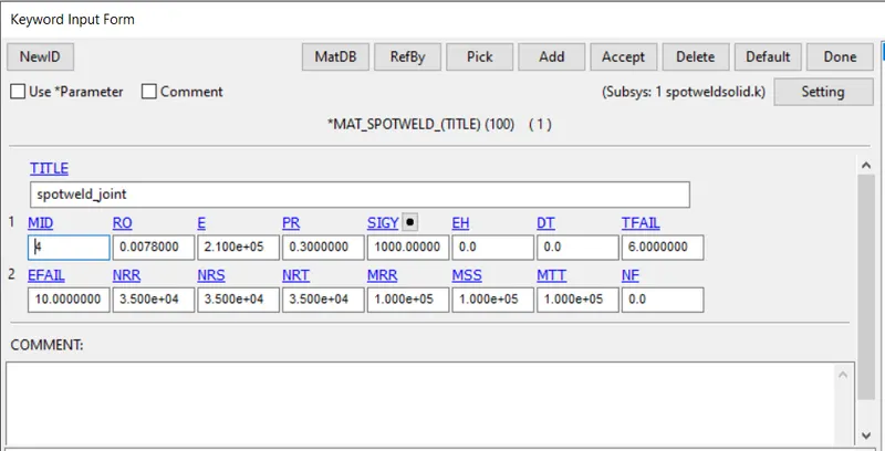
- Like the above steps, we need to follow the same steps for the solid spotweld method and run the keyword in ls manager to extract the results.
RESULTS:
- Here we extracted the results for both beam spotweld and Hexa spotweld and we can see the stress values from the figures.
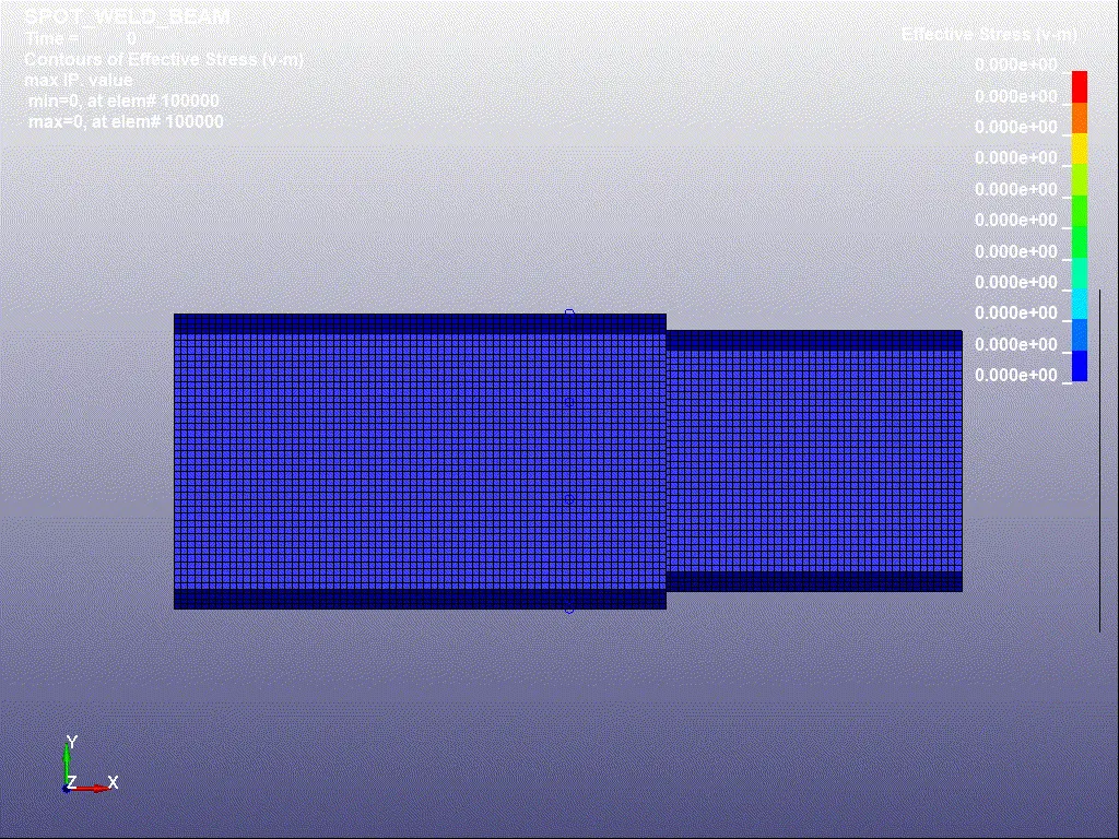
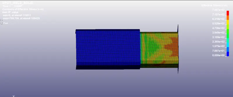
- Here we can extract the two types of stress values or simulations a. Beam element will not file due to larger time value of failure criteria and b. Beam element will fail due to the small-time value of failure criteria. For the above simulations, the beam is not failed due to the above-mentioned condition (a).
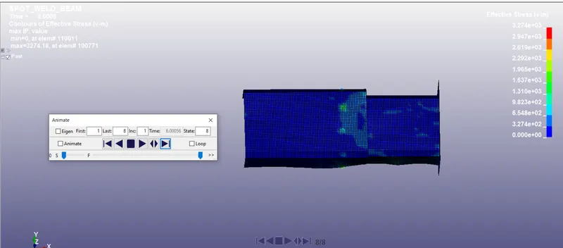
b. Here we can see that the beam brakes or fails and does not crash to the wall and stress are created here is low when compared to the above-mentioned method and the time value is tfail = 6ms.
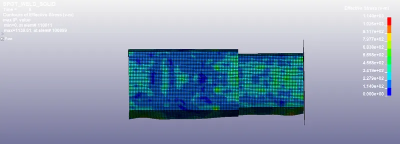
- Here we can see the solid element has a higher stress value when compared to the beam spotweld this is due to less absorption of stress from the Hexa element.
Section force:
- Here we are going to find the section force of both the simulations
i. Beam type
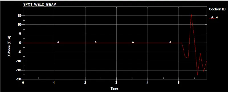
- From the plot, we can see that the middle section of the shell elements is shearing from 15N to -15N due to the beam elements.
ii. Solid element
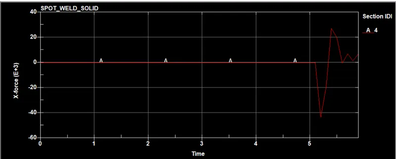
- From the plot we can see that shearing at the start is more and it is reduced to low with the help of the Hexa spotweld weld when comparing to the beam spotweld element.
Node velocity and acceleration at the section:
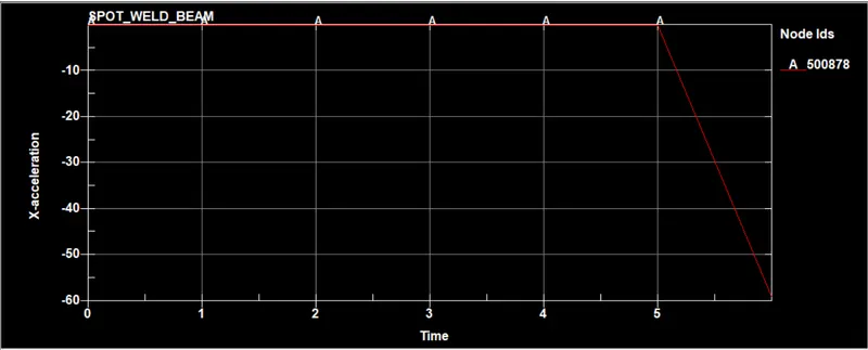
I. Beam spotweld:
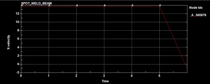
- From the plots, we can see that after hitting the wall direction of velocity is reversed due to the spotweld connection beam and we can see that velocity becomes zero at the section of the part.
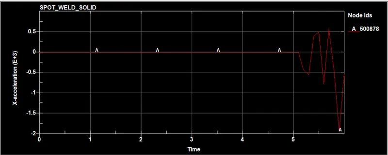
II. Solid spotweld element:
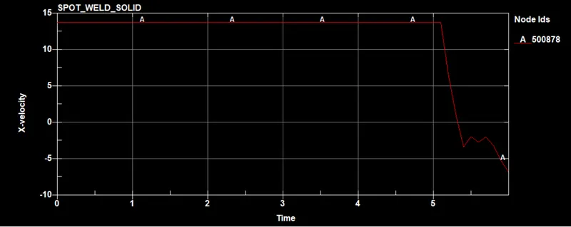
- From the plot, we can see that velocity is reversed same as the beam element spotweld but here velocity is not reduced to zero and it continues to the negative X-axis -5mm/ms.
Energy plots:
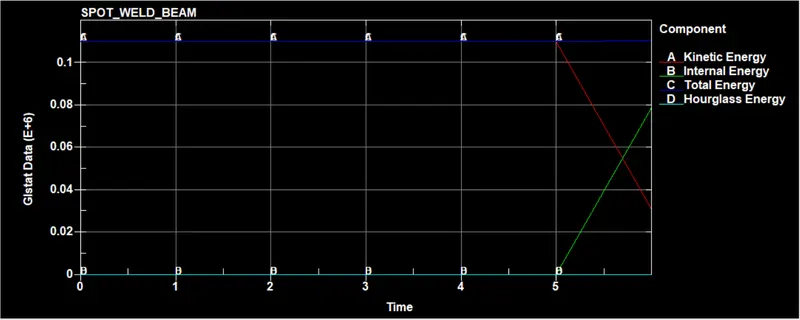
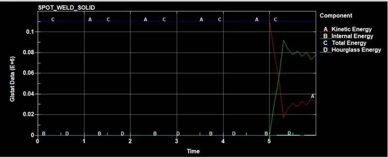
- From both the plots we can see that energy is distributed equally from internal energy to kinetic energy where hourglass and total energies are constant. More energy is released in the beam element spotweld when compared to the solid element spotweld.
CONCLUSION:
- The keywords necessary to build the spot weld modeling analysis were created from scratch.
- The model was solved successfully and the results are compared for both the cases i.e. (i)spotweld modeled as beam element (ii) Spotweld modeled as Hexa element.
- The force transferred in the first case is better than in the second case.
- The maximum stress and strain induced in the first case are more compared to the second case.
- The deformation of the spotweld is more in the first case compared to the second case.
- The first case is preferred for easy modeling with less computational time but for better results, the second case is preferred.
- Learned to build a solver deck for modeling spotweld as beam and Hexa element for crash analysis in LS-Dyna and extract the outputs to interpret and compare the results.