Week - 5 - Modelling Spotwelds
AIM :
To create a complete simulation file using Input Parameters from this to perform a Crash Box Simulation using Spotweld Beam & Solid element and Plot the Output results.
OBJECTIVE :
--> Input Parameters required for the simulation are listed below,
- Title Card,
- Section,
- Material Card,
- Part,
- Initial Velocity,
- Spotweld (Beam & Solid element)
- Contact,
- Control Card
--> Obtain the required Output results such as
- Input .k file and output files (d3plot, glstat, sleout, rcforc)
- Animation of the final simulation
- Cross-sectional force generated in the middle of the crash box (along its length)
- Plot Vonmises Stress contour plot
- Plot Axial and Shear force
- Plot of all energies (total, internal, kinetic, hourglass, sliding)
PROCEDURE :
1. Import the given Model in LS-PrePost using File-->Open-->LS-DYNA Keyword File option.
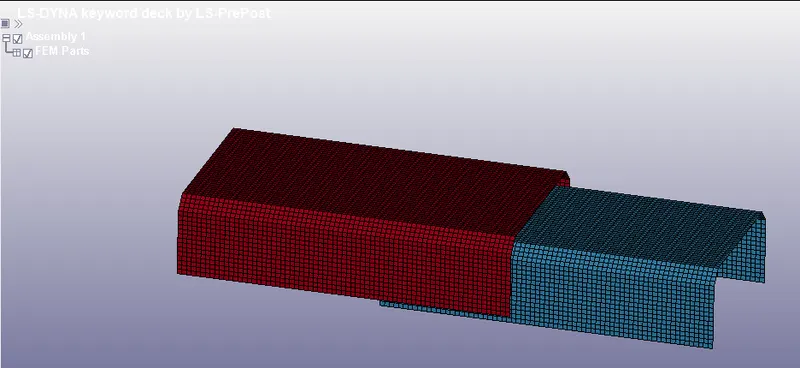
Fig: Imported Model
2. After Importing a Model, Set the Input Parameters using Model-->Keyword Manager option.
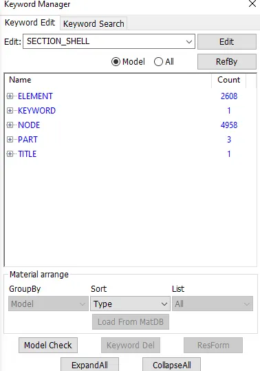
Fig: Keyword Manager
Title :
3. Create a Suitable Title for the simulation by using Keyword Manager-->Model-->Title option,
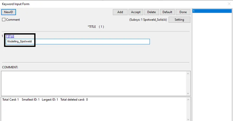
Fig: Creating a Title
Section :
4. Create a Section for Bottom Plate(Shell) and Phone(Solid) part.
5. Go to Keyword Manager-->All-->Section-->Shell option,
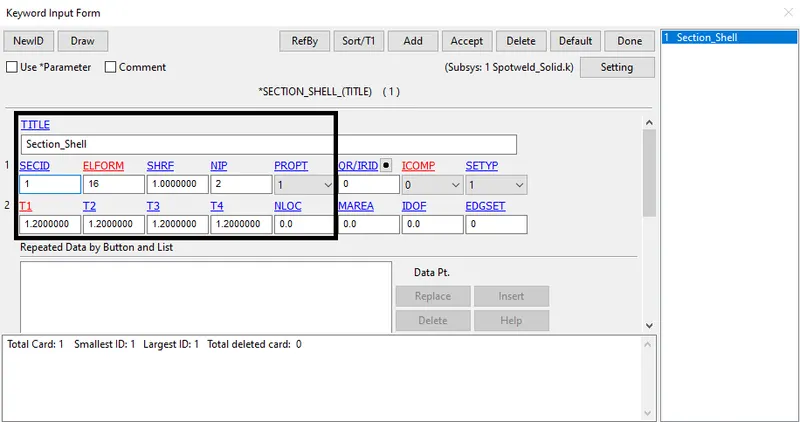
Fig: Creating a Section (Shell)
Material :
6. Create a Material for Bottom Plate and Phone.
7. Go to Keyword Manager-->All-->MAT-->024-Piecewise Linear Plasticity option,
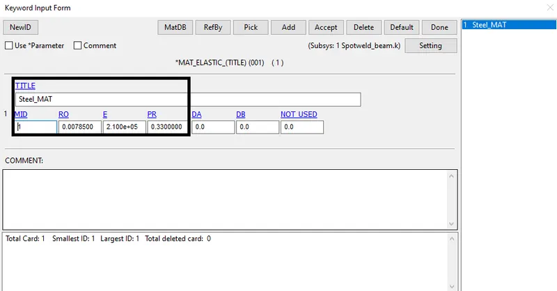
Fig: Creating Elastic Material
Part :
8. Create a Part by using Keyword Manager-->Model-->PART option and assign the Section ID & Material ID,
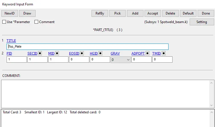
Fig: Creating a Part
Rigid Wall :
9. Create a Rigid wall by using Create Entity-->Rigid wall option and select the Planar option.
10. Use the 1n+NL option and select the node on a crash box to create a rigid wall.
11. Use the Tran option and assign the distance of the rigid wall away from the crash box.
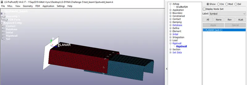
Fig: Creating a Rigid Wall
Initial Velocity :
12. Create an Initial Velocity for a crash box by using Create Entity-->Initial-->Velocity option.
13. Select the Crash box by using the "By Part" option and Click Apply-->Done.
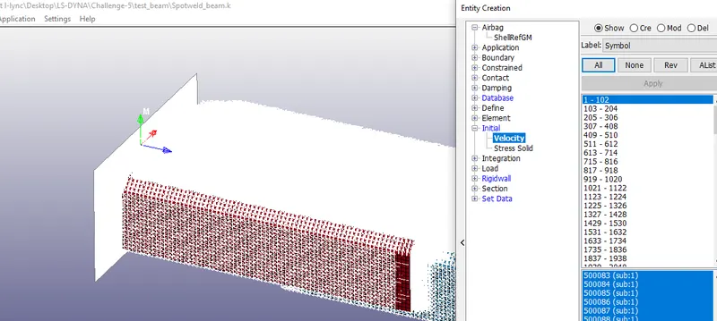
Fig: Creating an Initial Velocity
14. The spot-weld can be modeled as beam and solid elements by using the following techniques,
- To represent as a beam element, we use *CONTACT_TIED_SHELL_EDGE_TO_SURFACE card
- To represent as a solid element, we use *CONTACT_SPOTWELD card
Modeling Spotweld using Beam Element :
15. Creating Spotweld using Element Tool -->Element editing-->Create option and set Element type as Beam.
16. Select Node 1 & Node 2 and click Accept.
17. After creating all Beam elements, click Done.
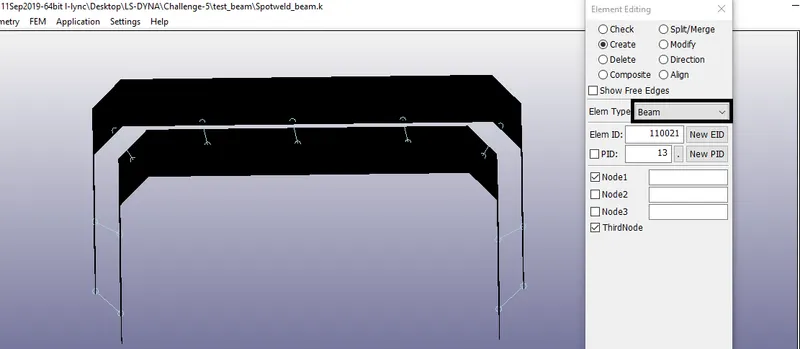
Fig: Creating Beam Element
Creating Material Card for Spotweld beam element :
18. For the beam element, the material card is assigned as the *MAT_100 that is especially for the spot weld material.
19. The values are assigned and here we are taking a time-dependent failure concept rather than the force-dependent failure concepts like Effective plastic strain, maximum axial stress, maximum shear stress, Force resultant, Torsional moment resultant, Moment resultant. So to keep this problem as a Time-dependent failure we given other failure terms as a higher value.
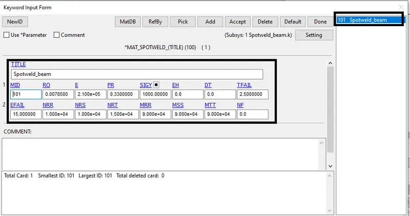
Fig: Creating a material card for beam element
Defining the Section card for Beam Element:
20. For the beam element, the section property is assigned by using the *SECTION_BEAM card. It is important to assign element formulation (ELFORM) as 9 because the *MAT_100 spot weld material model only applies for ELFORM 9 formulation in the case of the beam element. The cross-section type is selected as tubular since the default cross-section(rectangular) gives zero cross-section area during the simulation and the beam thickness at both ends is given as 3mm.
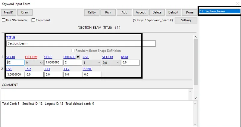
Fig: Creating a Section card for beam element
Defining the Contact card for beam element :
21. For the beam element, Contact_Tied_Shell_edge_to_surface is used. Here the master set id will be Part id and the Slave set id will be nodes of beam weld element.
22. For defining the Slave set select beam nodes so as to create the set and the steps is mentioned below, Entity Create > SetData > *SET_NODE > Pick the nodes > Apply.
23. For defining the Master set select both the metal sheet parts and the steps is mentioned below, Entity Create > SetData > *SET_PART > Pick the part > Apply.
Fig: Creating a contact card for beam element
24. Also, we need to create an Automatic_single_surface contact card for the parts to ensure that after the spot weld breaks the parts come to each other they shouldn't penetrate. Here the parts-sets are the slaves
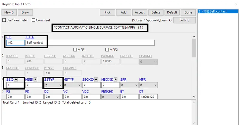
Fig: Creating a contact card for sheet metal parts
Modeling Spotweld using Solid Element :
25. The spot weld modeled using solid element is created by selecting the Element Tools > Element Editing > Create > Type - Hexa > Pick four desired nodes from the bottom and top sheet metal > Accept > Done.
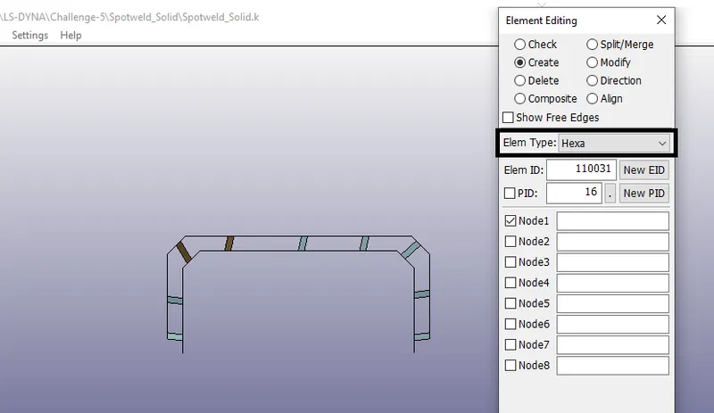
Fig: Creating Solid Element
Creating Material Card for Spotweld Solid element :
26. For the solid element, the material card is assigned as the *MAT_100 that is especially for the spot weld material. The values are assigned and here we are taking a time-dependent failure concept rather than the force-dependent failure concepts like Effective plastic strain, maximum axial stress, maximum shear stress, Force resultant, Torsional moment resultant, Moment resultant. So to keep this problem as a Time-dependent failure we given other failure terms as a higher value.
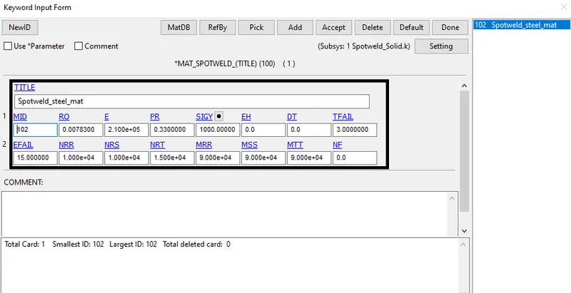
Fig: Creating a material card for Solid element
Defining the Section card for Solid Element:
27. For the solid element, the section property is assigned by using the *SECTION_SOLID card. It is important to assign element formulation (ELFORM) as 1 because the *MAT_100 spot weld material model only applies for ELFORM 1 formulation in the case of the solid element.
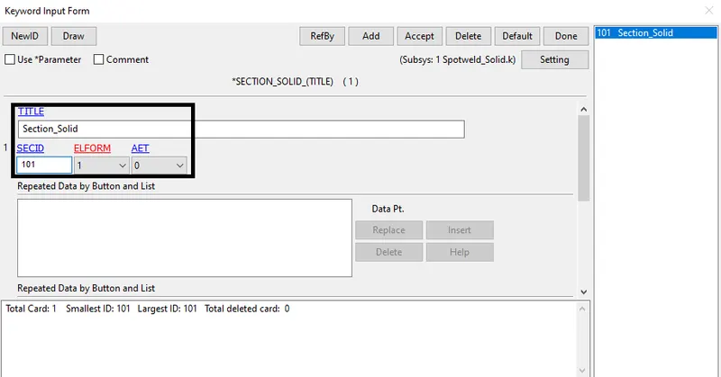
Fig: Creating a Section card for Solid element
Defining the Contact card for Solid element :
28. Here for the solid element, the contact type to be used is the *CONTACT_SPOTWELD card. Here the master set id will be Part id and the Slave set id will be nodes of solid weld element.
29. For defining the Slave set select solid nodes so as to create the set and the steps are mentioned below, Entity Create--->SetData--->*SET_NODE--->Pick the nodes>Apply.
30. For defining the Master set select both the metal sheet parts and the steps are mentioned below, Entity Create--->SetData--->*SET_PART--->Pick the nodes>Apply.
31. The command used to create a contact interface for the beam element is Model & part--->Keyword manager--->contact--->Spotweld is selected.
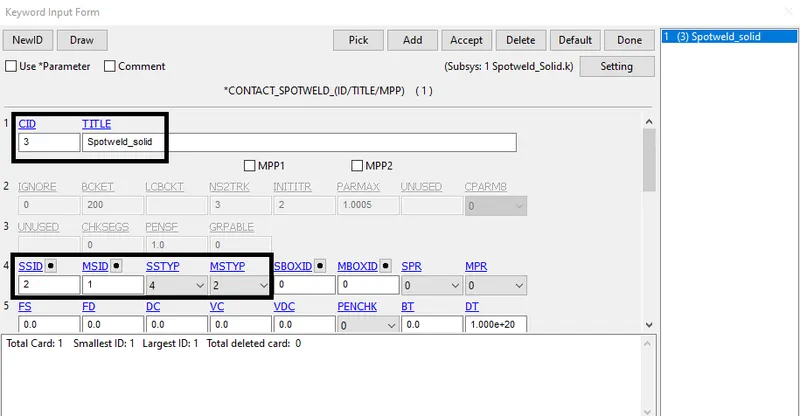
Fig: Creating a contact card for Solid element
Control :
32. Create a Control card using Keyword Manager-->All-->Control-->Termination option,
33. Here the time to end the simulation can be calculated analytically by using the distance between the rigid wall and component ie,15mm, and the velocity of the crash box ie,13.8889 mm/ms. End time, t = (15mm)/(13.8889 mm/ms) = 1.0799ms
34. The calculated time is 1.4399ms but extra time is considered after the impact in simulation ie, the crashing and the bouncing back of the crash box. So, the total time of 5ms is assigned as end time in the *CONTROL_TERMINATION card.
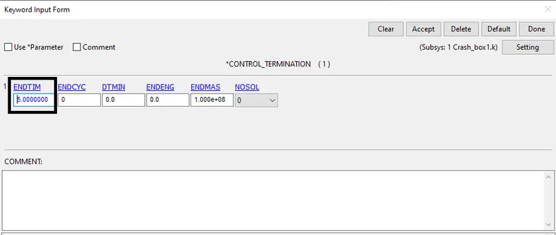
Fig: Creating Control Card
Cross-section :
35. For generating sectional force in the middle of the crash box, create a Cross-section.
36. Go to Create Entity-->Set Data-->*Set_Node for node-set and Create Entity-->Set Data-->*Set_Shell for Element or Shell set.
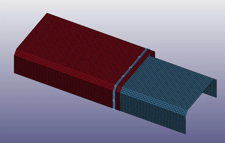
Fig: Creating Cross-section (Node-Set & Shell-set)
Output Requests :
37. Create an Output request to obtained plot results from the crash box simulation.
38. Go to Keyword Manager-->All-->Database-->Binary_D3Plot option and set the time step(Dt),
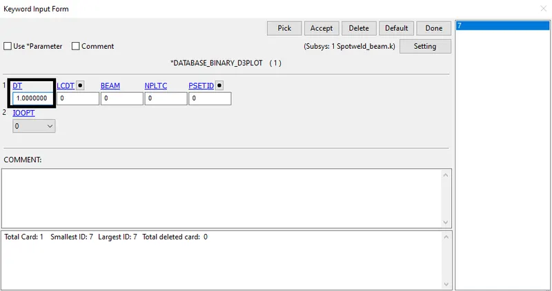
Fig: Time Step for getting output Plot results
39. Go to Keyword Manager-->All-->Database-->ASCII_option and Select GLSTAT option and set Dt value to get Energy plot results,
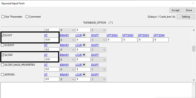
Fig: Time Step for getting Energy Plot results
Model Check :
40. Finally, Check the Model for Errors and Warnings using Keyword Manager-->Model Check option,
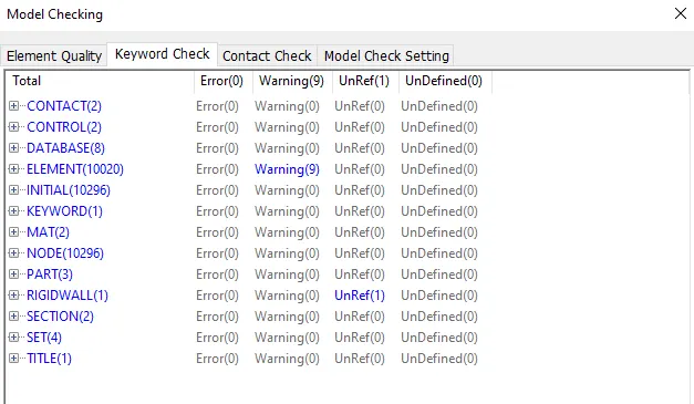
Fig: Model Checking
41. After Model Checking, Run the Simulation using File-->Run LS-DYNA option,
42. In the LS-RUN window, import the keyword file and Run the simulation.
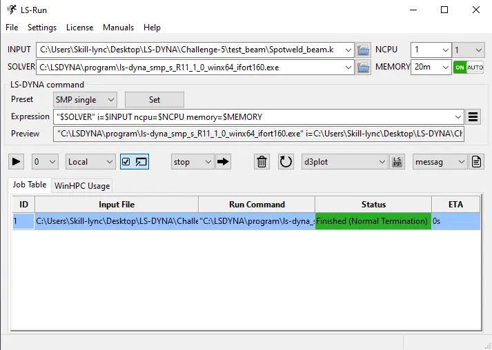
Fig: LS-Run Window
OUTPUT RESULTS :
Von mises Stress Plot :
Spotweld_Beam :
Spotweld_Solid :
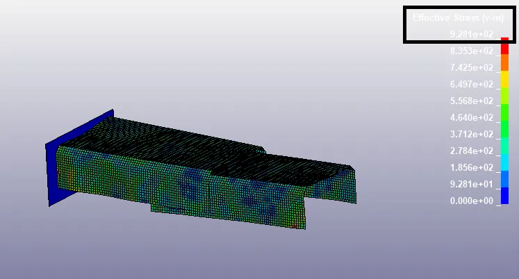
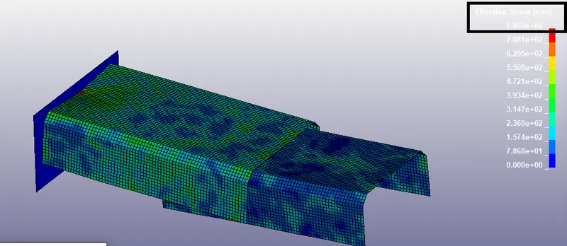
- The Effective Stress (von Mises stress) is used to predict the yielding of materials under complex loading from the results of uniaxial tensile tests. The von Mises stress satisfies the property where two stress states with equal distortion energy have an equal von Mises stress. The Vonmises Stress plot shows that, While Deformation occurs, Stress will be created and Maximum stress is 7.868E+02`N/(mm)^2` for Spotweld Beam element & 9.281E+02`N/(mm)^2` for Spotweld Solid element.
Energy Plot :
Spotweld_Beam :
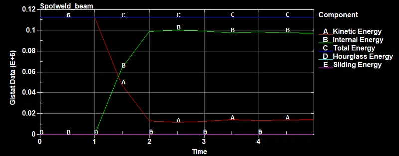
Spotweld_Solid :
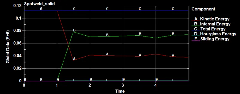
-From the plots above ie, the study of the beam and solid weld, here initially the sheet metal parts had a velocity of 13.8889mm/ms and as they impacted the rigid wall we can able to see that the Kinetic Energy of the component is been decreased and between in terms internal energy of the component is been increased higher and the hourglass energy is fall to zero as we controlled it in both the case study. The total energy of the system remains constant.
Sectional Force Plot :
Spotweld_Beam :
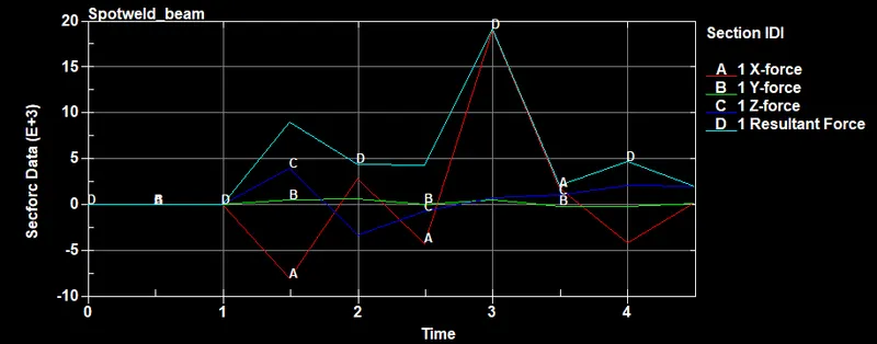
Spotweld_Solid :
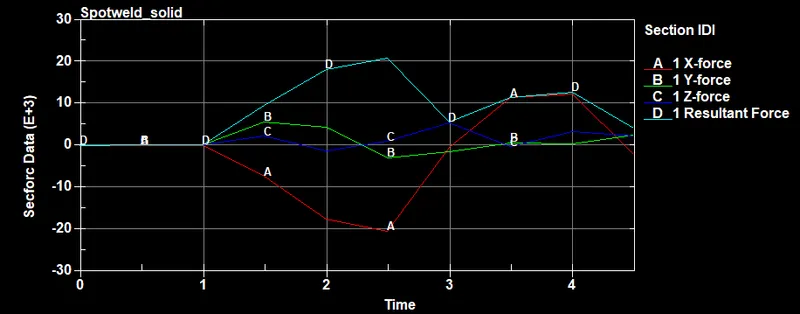
- From the above Cross-Section plot observed, the Sectional force is created for the middle of the Crash_box and we can see that the force value at the Y and Z direction after impact is very low since the velocity value is in the X-direction. At the impact time, we can see that the force value in X-direction peaks up and goes down after the bounce-back of the crash box. Comparing both plots, a Spotweld beam is obtained more force than Spotweld Solid during the Crash Simulation.
Axial Force & Shear Force Plot :
Spotweld_Beam :
Spotweld_Solid :
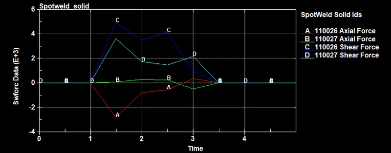
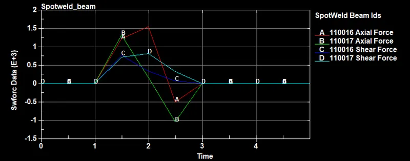
-Here the study carried out by modeling the spot weld at the 9 locations ie, 3 numbers each at the left and right sides as shown in the above figures and 3 numbers at the top side so that the top and bottom metal sheet parts are held together.
-The problem with the beam element is that it takes load only in the one direction as focussed and shear load is not easily understandable from the results. So in the above figure too, we can see that the higher axial forces can be seen compared to shear forces for spot welds modeled by the 1D beam element. The force values drop to zero after the spot weld fails (ie, after 1.5ms). Whereas, higher shear forces are notices comparatively to axial forces for spot welds modeled by solid elements. The force acting on the spot weld is in the transverse direction (perpendicular to the axis) since the solid element gives the force-resisting ability in the transverse direction, higher shear force values are notices for a solid element than beam element.
CONCLUSION :
The Crash box with a velocity of 13.8889mm/ms is impacted on the rigid wall having a Spotweld Beam & Solid element and obtained the output results for both cases and compared the output plots such as Vonmises Stress, Sectional force, Energy Plot, Axial, and Shear force.