Modelling Spotwelds in LS-DYNA
AIM -
Modeling of Spot Weld for Beam and Solid Element in LS-DYNA
OBJECTIVE -
- Checking the failure of the spot weld in the beam element
- Checking the failure of the spot weld in the solid element
- Comparison of the axial and shear force among beam and solid element.
#Case I - Checking the failure of the spot weld in the beam element
- Generate the beam element using Mesh Module.
To represent the spot weld between the two parts the user utilizes the mesh tool available on the left side of the PrePost GUI. As shown below after selecting the mesh tool next is to create the element for that element generation as the sub tool is selected. Here the user creates the beam element by selecting the node-set of the beam as shown below.
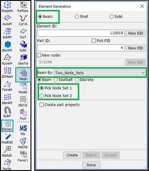
fig - Mesh Tool
SpotWeld is created as shown below.
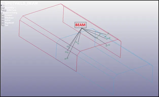
fig - BEAM SPOTWELD
- Setting the Solver Deck for Analysis
To check the strength of the spot weld using the beam element the user has to set up the solver deck to analyze the result. This is done by creating all the required keywords from the keyword manager. All these keywords are explained in the good manner below to understand the key terms used in it.
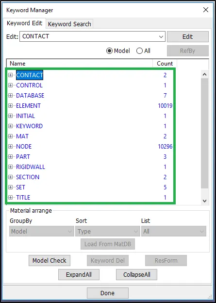
fig - Solver Deck Preparation
#Deleting the section and material card for the Beam
After the creation of the beam elements, LS-Dyna by default creates a discrete section card and material card. The user deletes the by default card and creates a new card.
#KEYWORDS FOR BEAM SPOT WELD:
#1 - MAT
Defining the Material Card for Beam and Shell Elements
The user-created 2 material cards to represent the material both for each Beam (Spot Weld) and Shell Elements.
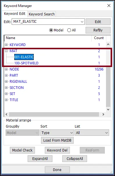
fig - Material Definition
ELASTIC MATERIAL FOR SHELL ELEMENTS
In the LS DYNA manual, the ELASTIC material is available to represent the elastic behavior of the components. The user selects this material from the keyword manager.
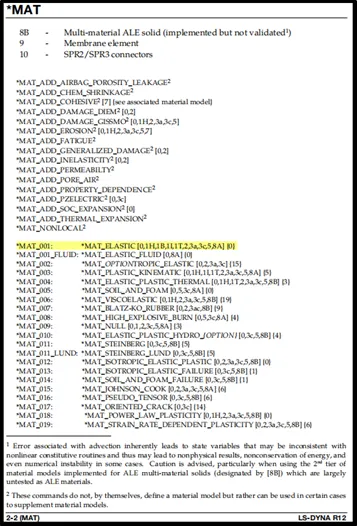
*MAT_ELASTIC or *MAT_001
This is Material Type 1. This is anisotropic hyperelastic material and is available for beam, shell, and solid elements in LS-DYNA.
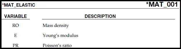
The shell elements are represented using the elastic material assuming the shell will regain its shape and size after the deformation. Steel material properties are considered for the Shell Elements as shown below,
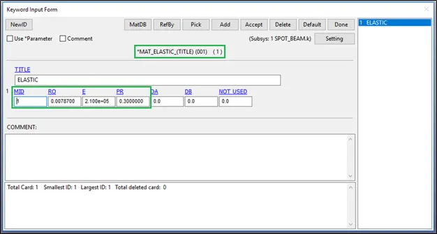
fig - Defining the Elastic Material to the Shell Elements
MAT100 FOR SPOT WELD BEAM ELEMENTS
*MAT_SPOTWELD
This is Material Type 100. The material model applies to beam element type 9 and to solid element type 1. The failure models apply to both beam and solid elements.
The beam elements, based on the Hughes-Liu beam formulation, are placed between any two deformable shell surfaces and tied with TIED SHELL EDGE TO SURFACE contact.
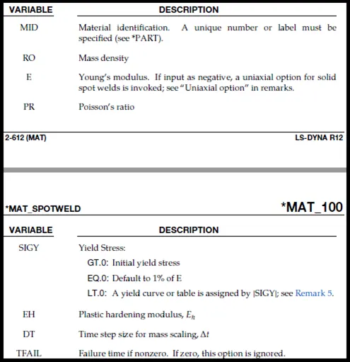
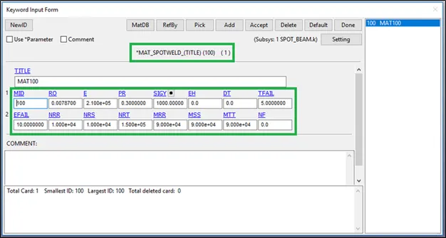
fig - Defining the Material Card for the Spotweld
Steel material properties are added for RO, E, and PR.
Beam and solid element force resultants for MAT_SPOTWELD are written to the spot weld force file, swforc, and the file for element stresses and resultants for designated elements, elout.
The user wants to fail the spot weld based on time failure for the best simulation so that is why the TFAIL value of 5 ms is set as the failure time.
Rest other parameters EFAIL, NRR, NRS, NRT, MRR, MSS and MTT are default.
#2 - SECTION
Defining the Beam and shell Card for Beam and Shell Elements
Section cards are created to define the element formulation, integration rule, nodal thicknesses, and cross-sectional properties are defined.
Two section cards are created. One section is defined for the beam element and the other one is created for the shell element.
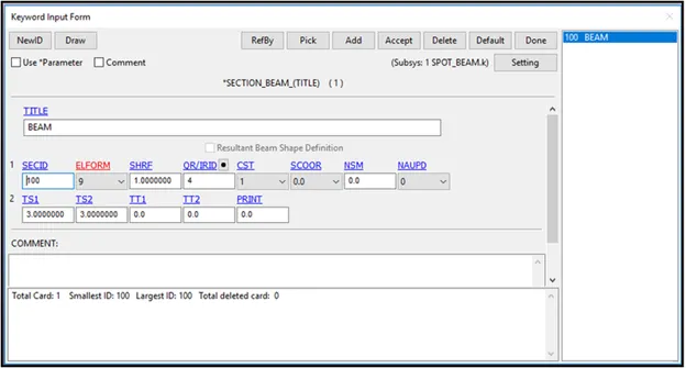
For beam elements, the element formulation ELFORM 9 is selected because ELFORM 9 is used especially to represent spot welds for beam elements.
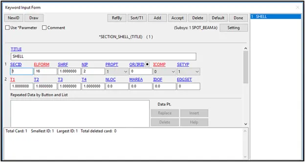
fig - Defining Section Card for BEAM & Shell Elements
For Solid elements, the element formulation ELFORM 16 is selected because it defines the fully integrated element with faster speed.
#3 - PART
Assigning the Material and Section Card to the Part
As the user knows that there are three parts to the model. One by one each part is assigned with the respective material card and section card.
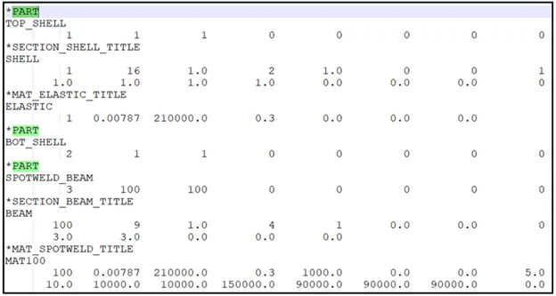
fig - Assignation of MAterial and Section Card to the Parts
#4 - RIGID WALL
Defined Rigid Wall
To check the failure of the spot weld the user creates a planar rigid wall. This rigid wall is fixed at 10 mm from the shell element.
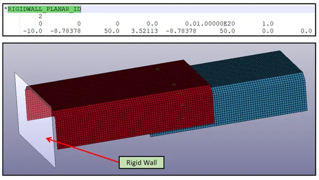
fig - Creation of Rigid Wall
#5 - NSET CREATION
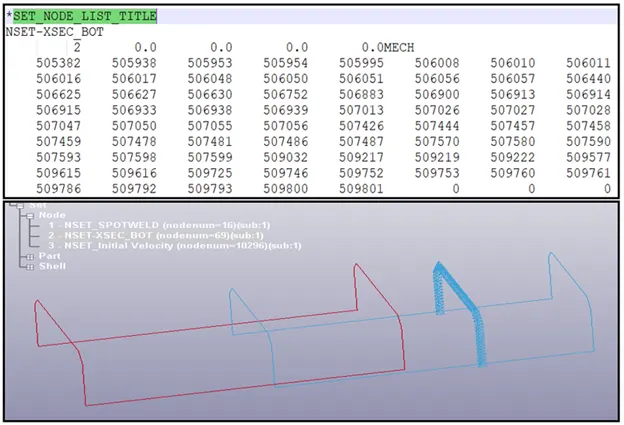
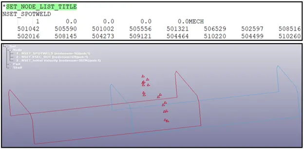
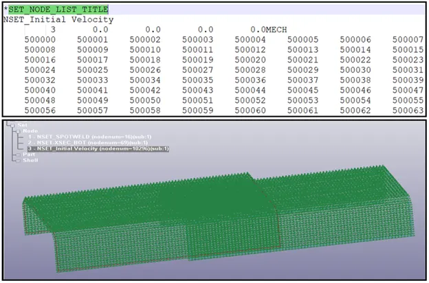
NSET is defined to find the output along with the required nodes. Here the user creates 3 NSET with their purpose and location as discussed below.
NSET for Sectional Force along with the Bottom Shell Elements
NSET for Beam Spot Weld
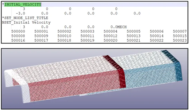
NSET for Initial Velocity
#6 - INITIAL VELOCITY
Defining the Initial Velocity to the NSET
The user defines the initial velocity to all the nodes as explained above. An initial velocity of 3mm/ms is applied as shown below.
#7 - CONTACT DEFINITION
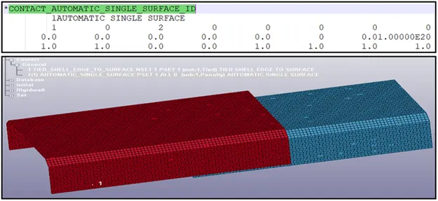
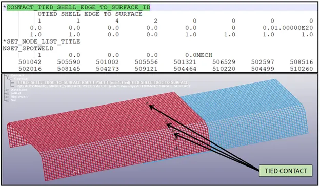
The keyword *CONTACT provides a way of treating interaction between disjoint parts. Here the user creates 2 types of contact. One between the shell element of both the shell elements using automatic single surface contact and one between the beam spot weld and shell element using tied contact.
AUTOMATIC SINGLE SURFACE FOR SHELL ELEMENTS
TIED SHELL EDGE TO SURFACE
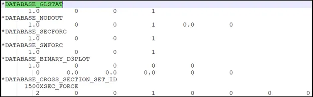
#7 -DATABASE OUTPUT REQUEST
To know the result the user creates the following output request using the Database Keyword. The output is requested at a time duration of 1 ms.
#8 -CONTROL TERMINATION
The user defines a time of 10 ms to terminate the simulation.

-----------------------------------------------------------------------------------------------------------------------------------------------------------------------------------------------------------------------------------------------------------------------
#Case II - Checking the failure of the spot weld in the solid element
- Generate the solid element using Mesh Module.
To represent the spot weld between the two parts the user utilizes the mesh tool available on the left side of the LSPP GUI. As shown below after selecting the mesh tool next is to create the element for that element edit as the sub tool is selected. Here the user creates the solid element by selecting the 8 node-set of the Hexa Element type as shown below.
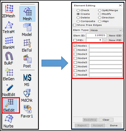
fig - Mesh Tool
Solid SpotWeld is created as shown below.
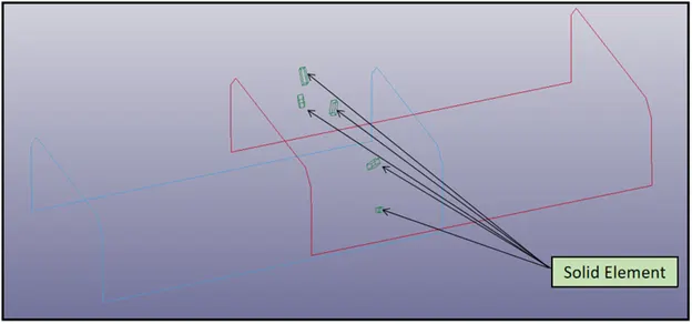
fig - Solid Element Spotweld
- Setting the Solver Deck for Analysis
To check the strength of the spot weld using the solid element the user has to set up the solver deck to analyze the result. This is done by creating all the required keywords from the keyword manager. All these keywords are explained in the good manner below to understand the key terms used in it.
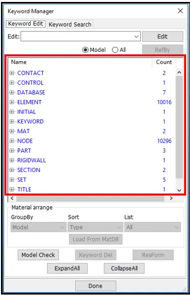
fig - Solver Deck Preparation
#KEYWORDS FOR SOLID SPOT WELD:
#1 - MAT
Defining the Material Card for Beam and Shell Elements
The user-created 2 material cards to represent the material both for each SOLID (Spot Weld) and Shell Elements.
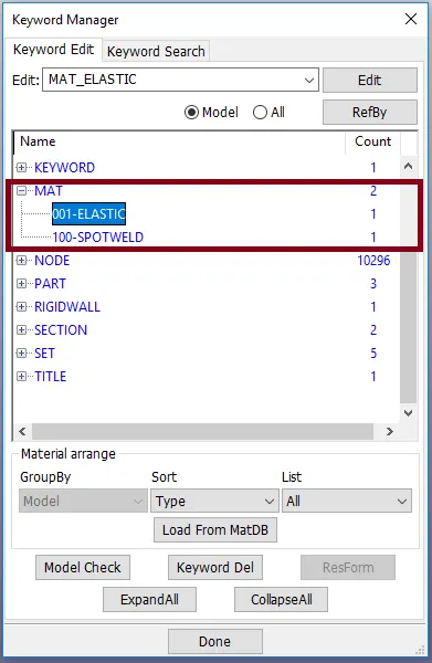
fig - Material Definition
ELASTIC MATERIAL FOR SHELL ELEMENTS
In the LS DYNA manual, the ELASTIC material is available to represent the elastic behavior of the components. The user selects this material from the keyword manager.
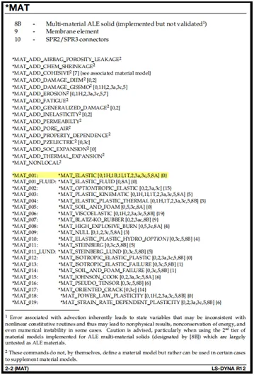
*MAT_ELASTIC or *MAT_001
This is Material Type 1. This is anisotropic hyperelastic material and is available for beam, shell, and solid elements in LS-DYNA.

The shell elements are represented using the elastic material assuming the shell will regain its shape and size after the deformation. Steel material properties are considered for the Shell Elements as shown below,
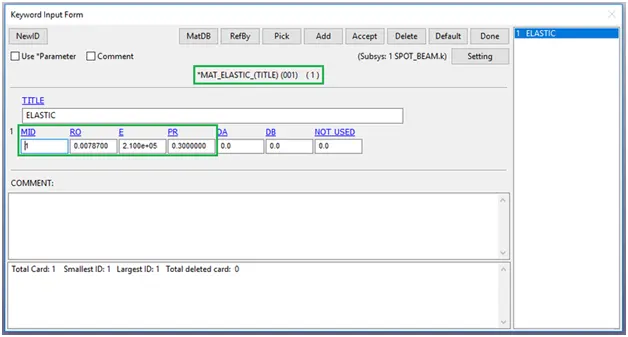
fig - Defining the Elastic Material to the Shell Elements
MAT100 FOR SPOT WELD BEAM ELEMENTS
*MAT_SPOTWELD
This is Material Type 100. The material model applies to beam element type 9 and to solid element type 1. The failure models apply to both beam and solid elements.
The beam elements, based on the Hughes-Liu beam formulation, are placed between any two deformable shell surfaces and tied with TIED SHELL EDGE TO SURFACE contact.
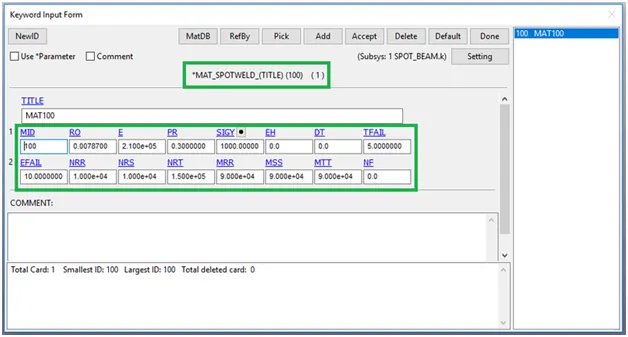
fig - Defining the Material Card for the Spotweld
Steel material properties are added for RO, E, and PR.
Beam and solid element force resultants for MAT_SPOTWELD are written to the spot weld force file, swforc, and the file for element stresses and resultants for designated elements, elout.
The user wants to fail the spot weld based on time failure for the best simulation so that is why the TFAIL value of 5 ms is set as the failure time.
Rest other parameters EFAIL, NRR, NRS, NRT, MRR, MSS and MTT are default.
#2 - SECTION
Defining the Beam and shell Card for Solid and Shell Elements
Section card are created to define the element formulation, integration rule, nodal thicknesses, and cross-sectional properties are defined.
Two section cards are created. One section is defined for the solid element and the other one is created for the shell element.
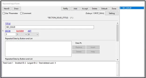
For solid elements, the element formulation ELFORM 1 is selected because ELFORM 9 is used especially to represent spot welds for solid elements.
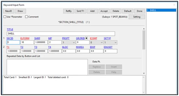
fig - Defining Section Card for SOLID & Shell Elements
For Shell elements, the element formulation ELFORM 16 is selected because it defines the fully integrated element with faster speed.
#3 - PART
Assigning the Material and Section Card to the Part
As the user knows that there are three parts to the model. One by one each part is assigned with the respective material card and section card.
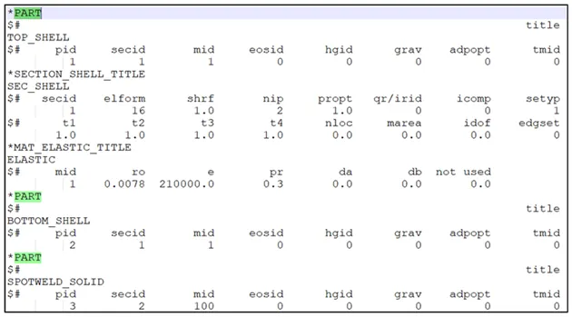
fig - Assignation of Material and Section Card to the Parts
#4 - RIGID WALL
Defined Rigid Wall
To check the failure of the spot weld the user creates a planar rigid wall. This rigid wall is fixed at 10 mm from the shell element.
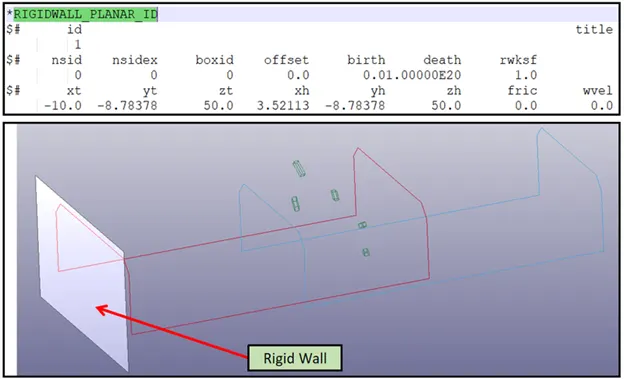
fig - Creation of Rigid Wall
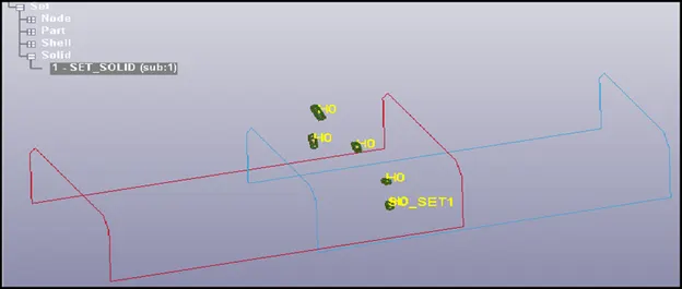
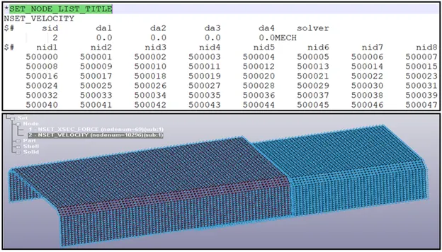
#5 - NSET CREATION
NSET is defined to find the output along with the required nodes. Here the user creates 3 NSET with their purpose and location as discussed below.
NSET for Sectional Force along with the Bottom Shell
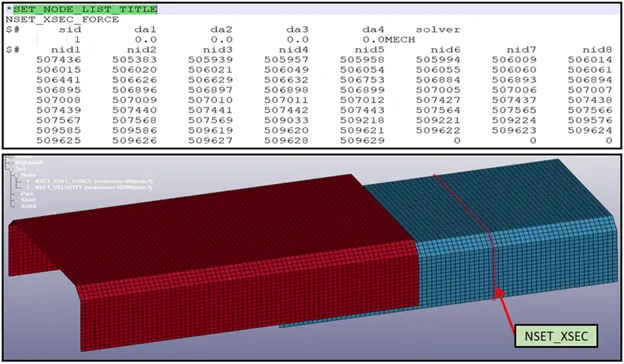
NSET for Solid Spot Weld
NSET for Initial Velocity
#6 - INITIAL VELOCITY
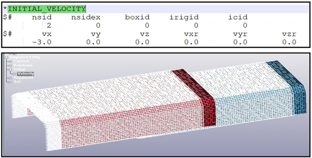
Defining the Initial Velocity to the NSET
The user defines the initial velocity to all the nodes as explained above. An initial velocity of 3mm/ms is applied as shown below.
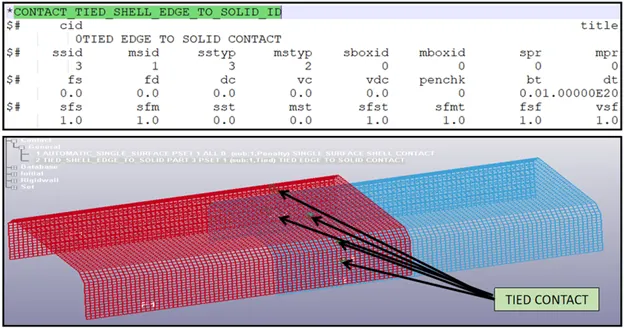
#7 - CONTACT DEFINITION
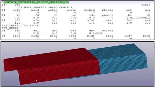
The keyword *CONTACT provides a way of treating interaction between disjoint parts. Here the user creates 2 types of contact. One between the shell element of both the shell elements using automatic single surface contact and one between the solid spot weld and shell element using tied contact.
AUTOMATIC SINGLE SURFACE
TIED SHELL EDGE TO SURFACE
#7 -DATABASE OUTPUT REQUEST
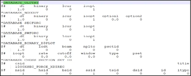
To know the result the user creates the following output request using the Database Keyword. The output is requested at a time duration of 1 ms.
#8 -CONTROL TERMINATION
The user defines a time of 10 ms to terminate the simulation.

-----------------------------------------------------------------------------------------------------------------------------------------------------------------------------------------------------------------------------------------------------------------------
#Result & Conclusion:
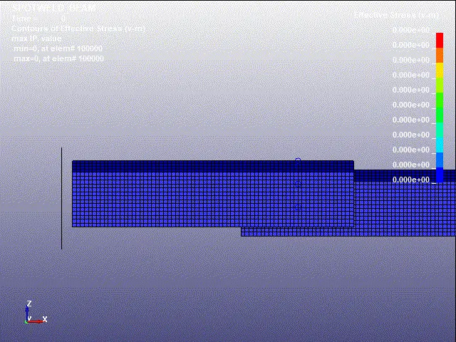
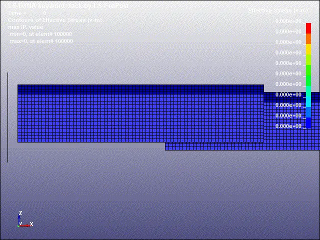
#GIF OF STRESS DISTRBUTION
BEAM SPOTWELD
SOLID SPOTWELD
#ENERGY PLOT
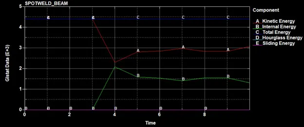
BEAM SPOT WELD
SOLID SPOT WELD
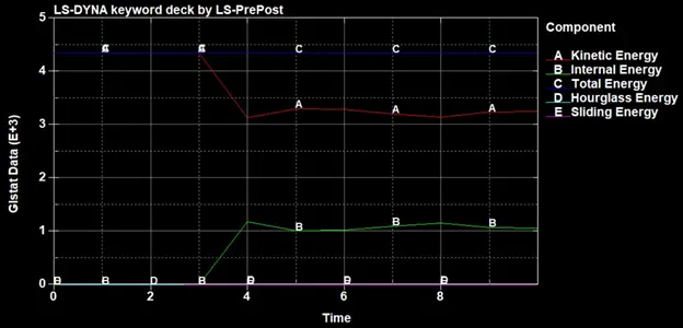
From the above two plots of energy's the user can conclude that the plots are following the equilibrium condition. We can see the total energy remains the same and the internal & the kinetic energy are converging due to the energy transformation and dissipation.
#AXIAL FORCE
BEAM SPOT WELD
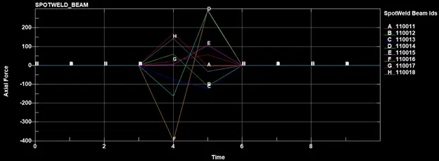
From the above plot user can conclude that during the impact with the rigid wall axial force is generated in the beam spot weld and the value of the maximum and minimum force generated is as mentioned below in the following element number which is belonging to the spot weld.
Element number:
Max on element number 110016 = 295 N
Min on element number 110013 = 10 N
SOLID SPOT WELD
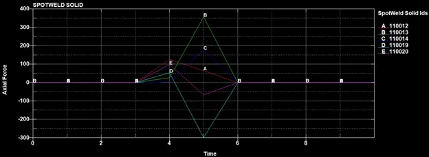
From the above plot user can conclude that during the impact with the rigid wall axial force is generated in the solid spot weld and the value of the maximum and minimum force generated is as mentioned below in the following element number which is belonging to the spot weld.
Element number:
Max on element number 110013 = 357 N
Min on element number 110019 = 53.9 N
#SHEAR FORCE
BEAM SPOT WELD
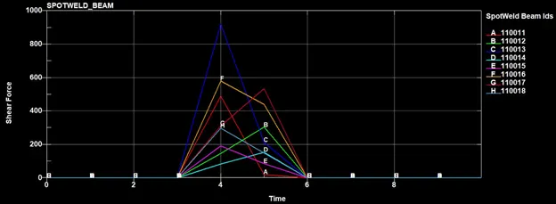
From the above plot user can conclude that during the impact with the rigid wall shear force is generated in the beam spot weld and the value of the maximum and minimum force generated is as mentioned below in the following element number which is belonging to the spot weld.
Element number:
Max on element number 110013 = 921.87 N
Min on element number 110014 = 154.336 N
SOLID SPOT WELD
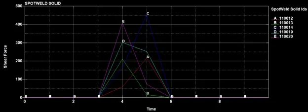
From the above plot user can conclude that during the impact with the rigid wall shear force is generated in the solid spot weld and the value of the maximum and minimum force generated is as mentioned below in the following element number which is belonging to the spot weld.
Element number:
Max on element number 110014 = 454 N
Min on element number 110013 = 210 N