Week - 5 - Modelling Spotwelds
AIM:
To obtain the axial and shear force by comparing the spotwelds between beam and solid sections.
PROCEDURE:
BEAM SPOTWELD SECTION:
Import the model .k file
Create the section card for the shell parts and assign the thickness as 2 mm and with elform 16.
Create the material card for both the shell parts.
Create the spotwelds using the elements generation option.
Assign the section for the soptweld as beam.
Use elform 9 for the beam element, with a thickness of 3mm.
Create the material card using mat 100 spoltweld and assign the fail time as 5ms as the element should fail at the half time of the total process time.
The properties of steel are imported to the material card.
This mat card is common for both the sections, ie, beam and solid.
Create the node set for both the spotwelds and the shell parts.
Create the contact card tied shell edge to surface and assign the master and slave nodes using the node sets assigned.
The master nodes are the shell node set and the slave nodes are the welds node set.
Create the control cards termination with the endtime as 10 ms.
Create the database card requesting the outputs from the ASCII such as glsat, secfrc, rwfrc and also the binary d3plot with dt as 1 ms for lsdyna to write the report every 1 ms.
Use the boundary option to create rigid at one end of the shell sections and the prescribed motion set to assign the motion to the component.
Create a load curve and assign it to the prescribed motion set.
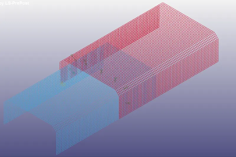
SOLID SPOTWELD SECTION
delete the beam elements created.
Create the spotwelds using the elements editing option and create the hexa elements.
Assign the section for the soptweld as solid with elform 1.
Use the same material card using mat 100 spoltweld
Create the node set for both the solid hexa elements.
Create the contact card spotweld and assign the master and slave nodes using the node sets assigned.
The above changes are only need to be done, as the other cards can be used as same.
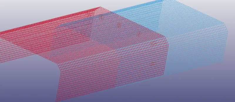
The axial and shear force of the component are shown below with graphs and explanations.
GLSTAT SHELL
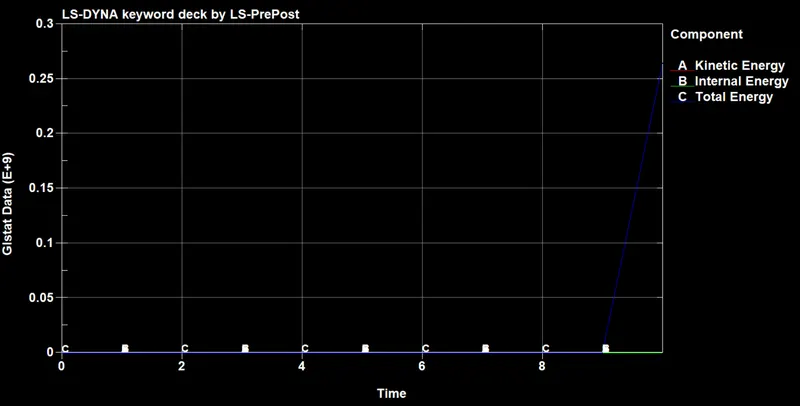
GLSTAT SOLID
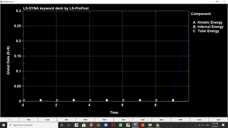
The total energy raises at the end of the operation at time 9ms for both the sections.
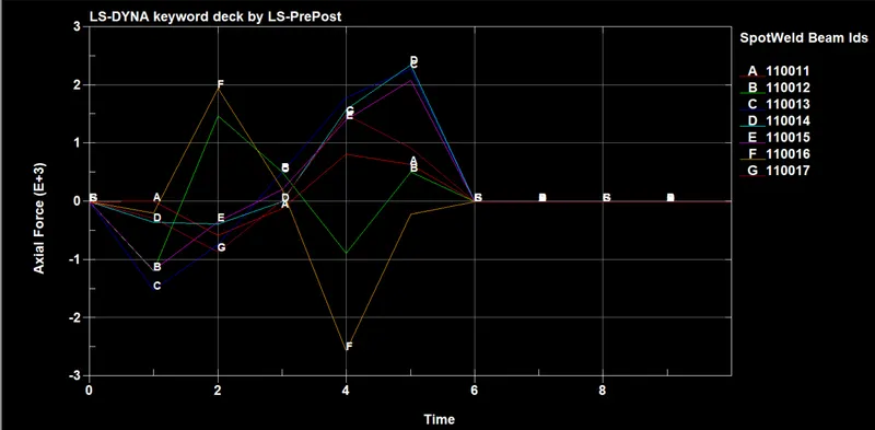
AXIAL SHELL
AXIAL SOLID
No observable cahnges can be seen between the two graphs, but the spot weld sections for all the sections do experience change in axial force at different time intervals.
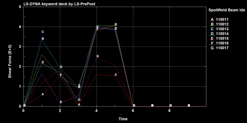
SHEAR SHELL
SHEAR SOLID
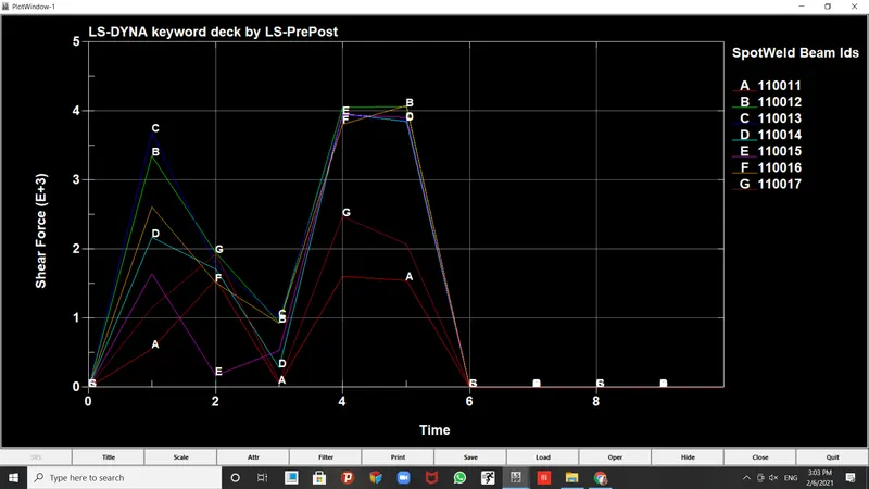
Both the shear graphs are identical but variations in the shear values happen with respect ot time.
Result:
Thus the spotweld are analysed using both the sections and the graphs are presented above.