Week - 5 - Modelling Spotwelds
Objective: Model spot welds for the given assembly of parts and run a crash and plot stress acted on welds.
Model:
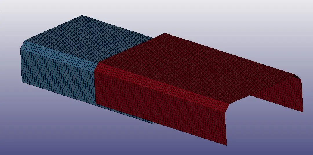
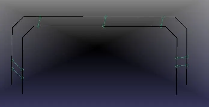
The spot weld is a rigid beam that connects the nodal points of the nodal pairs; thus, nodal rotations and displacements are coupled. The spot welds must be connected
to nodes having rotary inertias, that is, beams or shells.
Overview of the simulation of the spot welds as beam and solid elements:
Solid weld element Beam weld elements
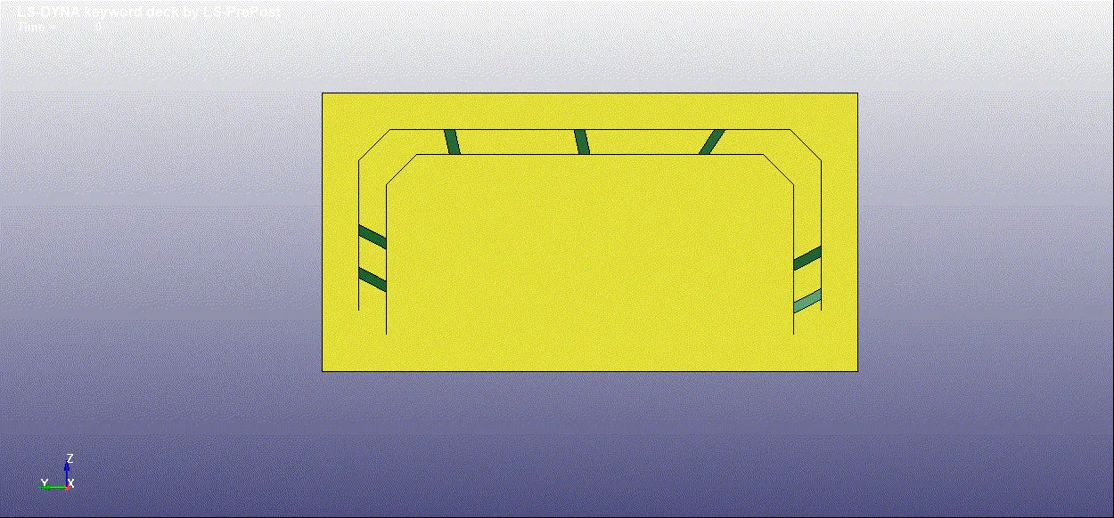
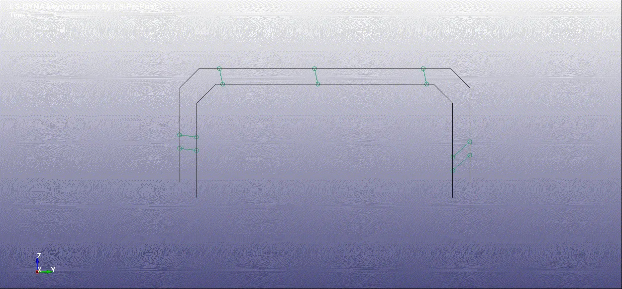
Modelling of SpotWeld:
Beam Elements:
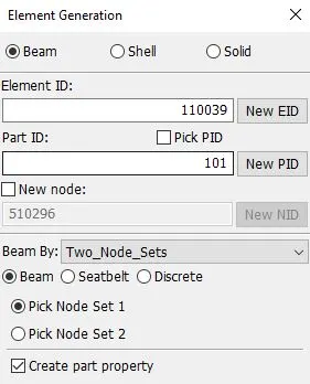
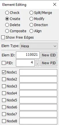
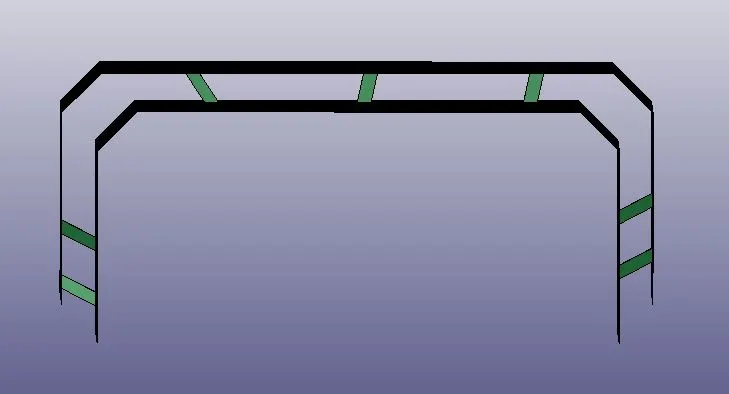
Solid Elements:
Unit Consistency:
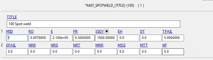
g-mm-ms-N-MPa.
Material Card:
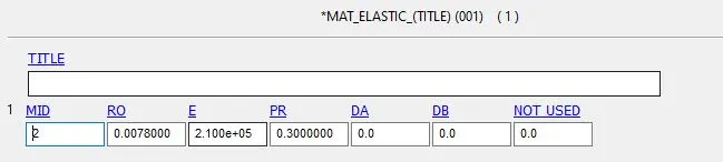
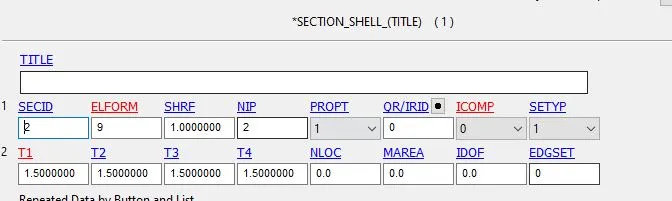
Shell
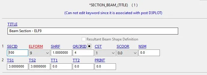
Beam Shell:
Solid Beam:

Beam Contacts:
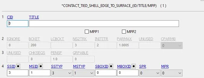
Shell contacts:
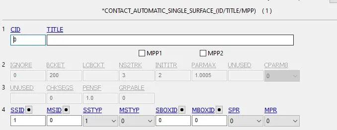
Constrained_Spotweld (Solid Beam Spot Weld)
Purpose: Define massless spot welds between non-contiguous nodal pairs. The spot weld is a rigid beam that connects the nodal points of the nodal pairs; thus, nodal rotations and
displacements are coupled. The spot welds must be connected to nodes having rotary inertias, that is, beams or shells.
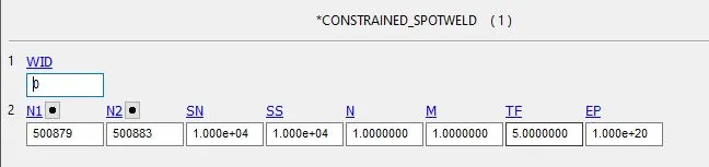
Control Cards:
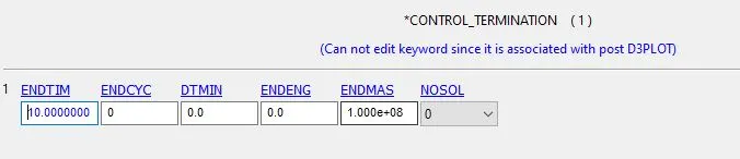
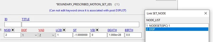
Boundary Conditions:
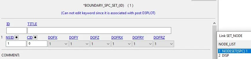
Results:
Von-Misses GIF:
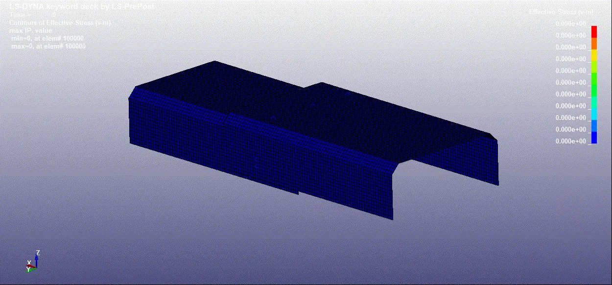
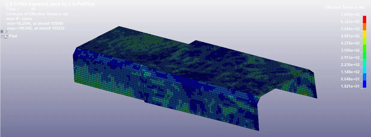
Von-Misses:
Axial forces acting on the beam elements spot welds:
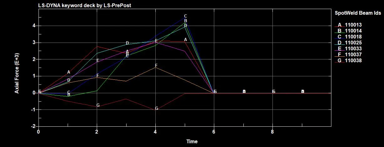
The maximum axial force identified to be acting on the spot the weld (110018) is 4.5E+3 N at 5ms.
Shear Force acting on the Beam spot weld:
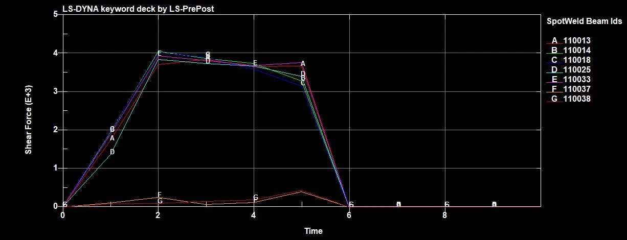
The maximum shear force acting on the spot the weld (110025) is 4.0E+3 N at 2ms.
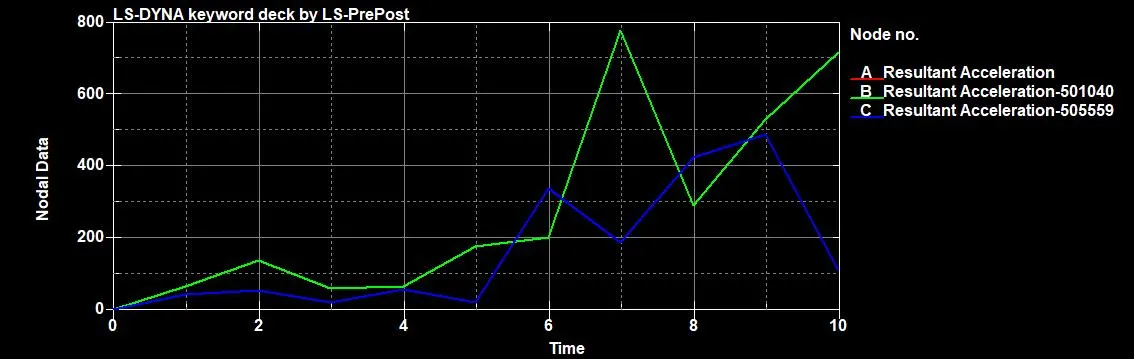
As we can see in the nodal acceleration plot (Both the nodes are from top and bottom respectively) that after the failure of spot welds there is a spike in the acceleration which represents that body detached from itself.
Solid Beam Results:
Created Rigid wall:
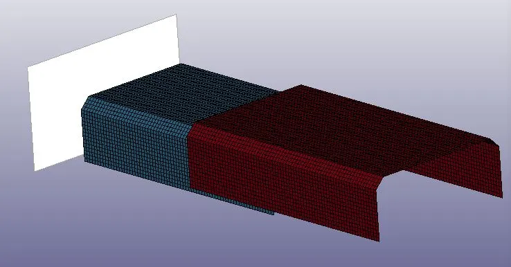
Initial Condition for Solid:

Directional Stress X-Stress :
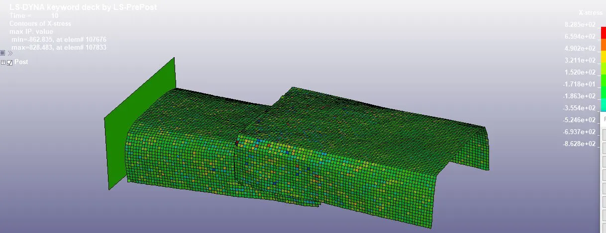
Maximum stress developed in the X direction is 8.28e+02 Mpa
Directional Stress Y Stress:
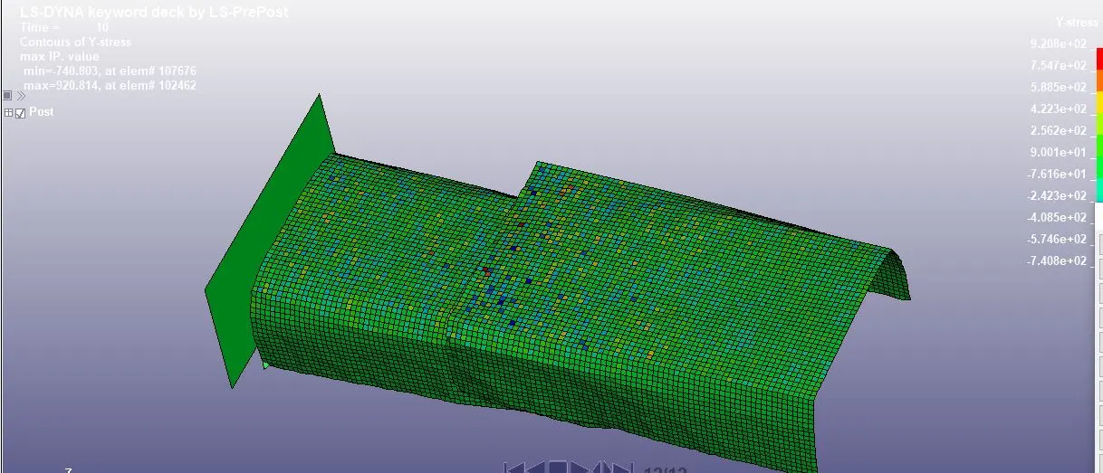
Maximum stress developed in the Y direction is 9.28e+02 Mpa
Von-Misses Stress: GIF
Axial Stress on the solid beam metal:
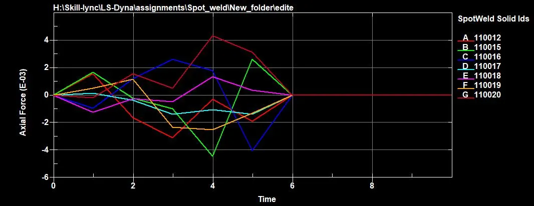
The maximum axial force acting on 110012 is 4.2E-03MPa at 4 ms.
The shear force acting on solid beam elements:
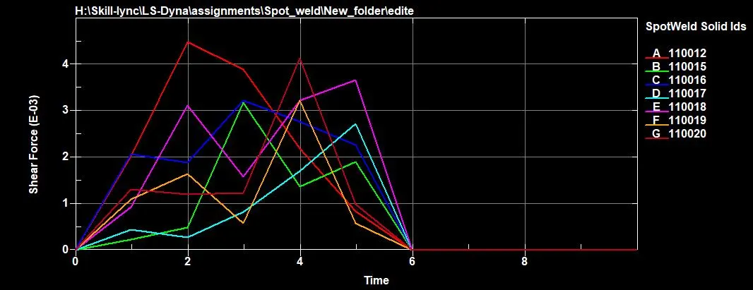
The maximum shear force acting on 110012 is 4.5E-03MPa at 2 ms.
Acceleration of a node from the middle of the model:
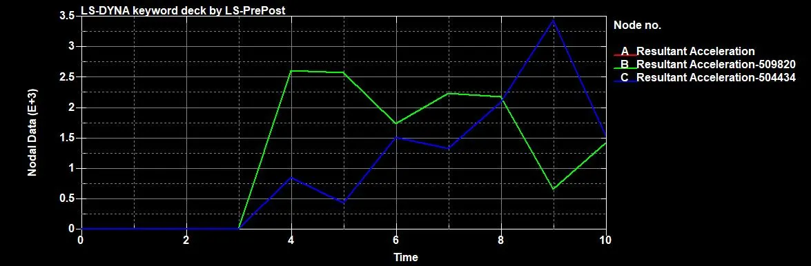 .
As we can see from the nodal acceleration plot that after the collision happened at 3ms there is a spike in the acceleration and at 4ms spot weld failed so after that there is a decrease in the acceleration.
Results:
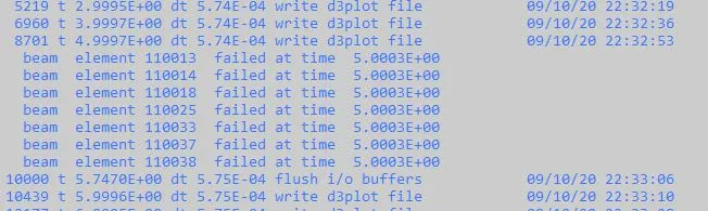
Beam failure:
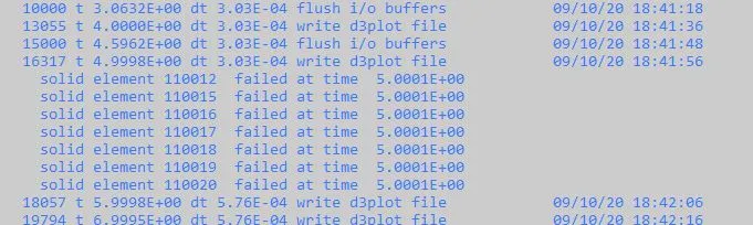
Solid failure:
| Serial No | Description | Beam | Solid |
| 1. | Axial Force | 4.5 E+03 | 4.2 E - 03 |
| 2. | Shear Force | 4.0 E+03 | 4.5 E - 03 |
Conclusion:
In here beam has been given some thickness which is less when compared to its thickness. So, tensile resistance is maximum. That is why the Axial force of beam elements in more than solid elements.
The width and thickness of the solid elements are observed to be 3.5mm(approx.) which the Beam element lacks which indicates that the Solid elements are more preferable when there is any uncertainty of which element to be considered.
The control energy card was created to take care of Hourglass energy in addition, the ELFORM-9& 16 for beam and solid element sections are set to spotweld beam and fully integrated shell element respectively which has no Hourglass deformation.
The Failure of all the elements both beam elements and the solid elements at half the termination time i.e,(5ms)