Week - 5 - Modelling Spotwelds
OBJECTIVE
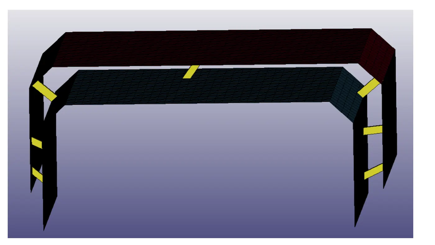
- In this assignment, you will model spotwelds for the given assembly of parts and run a crash test similar to the one in assignment 4. Details about spotweld location is in the image below. The yellow line signifies the spotweld directions. You need to use 3-7 spotwelds along this line, in a symmetric manner, before running the simulation.The spotwelds should be modeled using beam elements and solid elements separately. While using solid elements, one spotweld should have one solid element. The axial and shear force should be compared among beam and solid elements. The same material card using *MAT_SPOTWELD should be used for both beam and solid elements. You can use steel material data for *MAT_SPOTWELD cards and calibrate the failure data according to your results. The best simulation should have a failure at half of the termination time.
- All deliverable exactly similar to assignment 4 but beam and solid spotweld results should be compared in relevant cases.
GEOMETRY
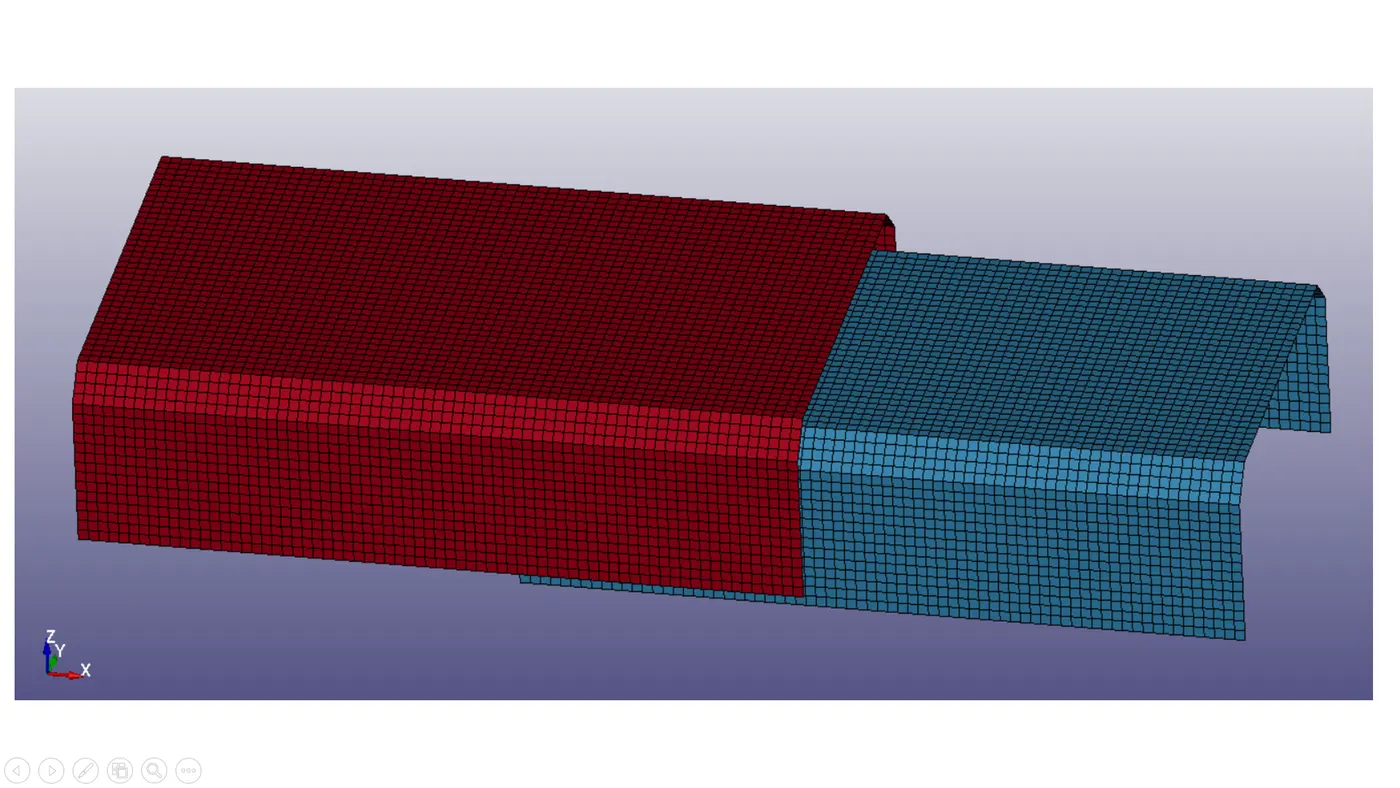
The upper and lower metal sheets are meshed with shell elements. These two metals sheets have to be conncted with spot welds using beam and solid elements separately.
PROCEDURE
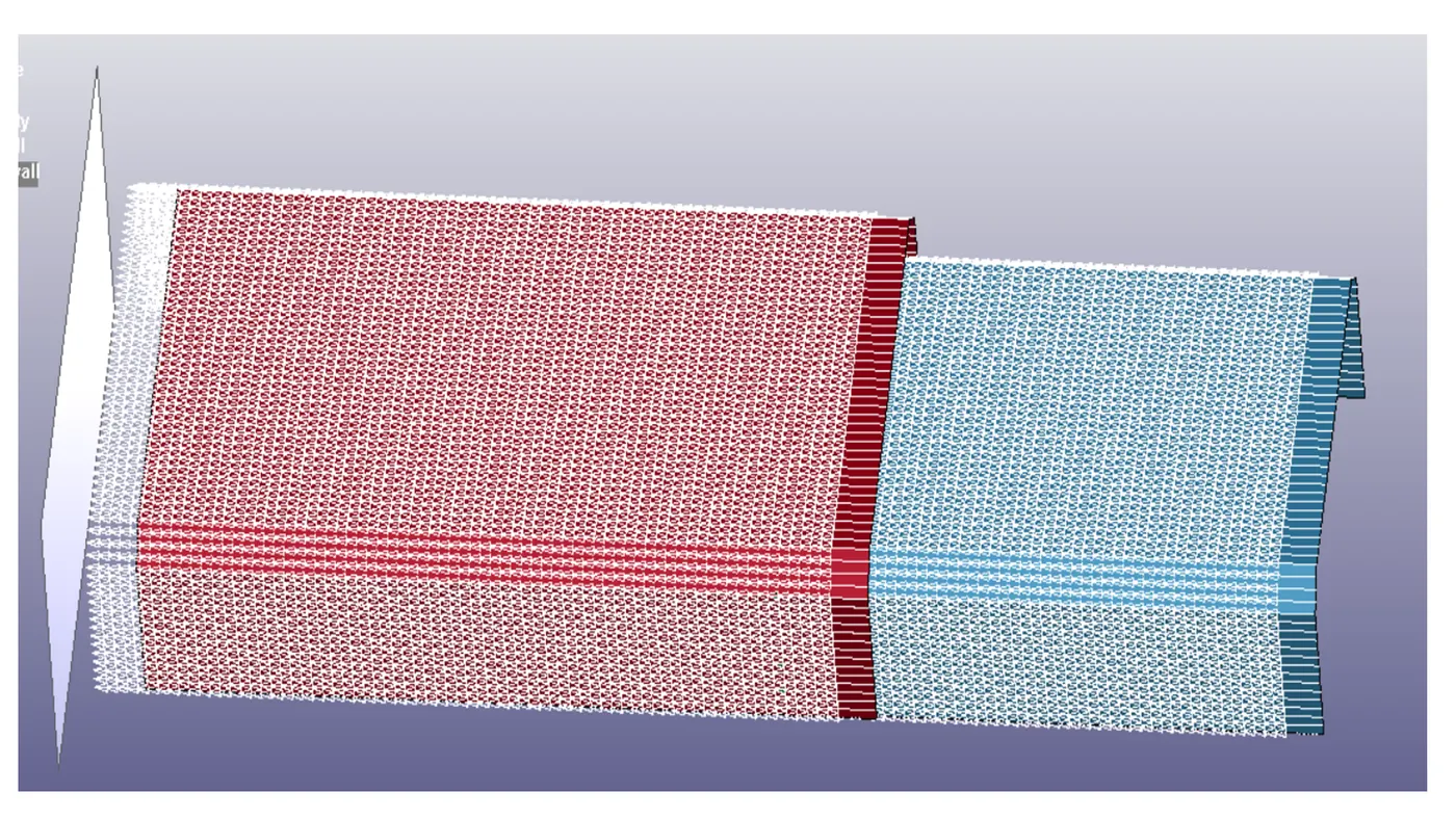
The crash test on this model is done similarly to challenge 4 by creating the rigid wall away from the component by 10 mm distance. The same velocity boundary condition is given to both the metal sheets (13.889 mm/ms). The spot weld modelling needs some extra card definitions which will be discussed below.
Basically spot weld can be modelled in the following ways.
- Using beam element and tied contact
- Using constraint spotweld
- Using constrained generalized
- Using solid element and spot weld contact.
We will model spot weld for this assignment first and fourth method.
BEAM
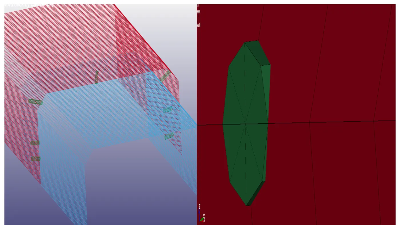
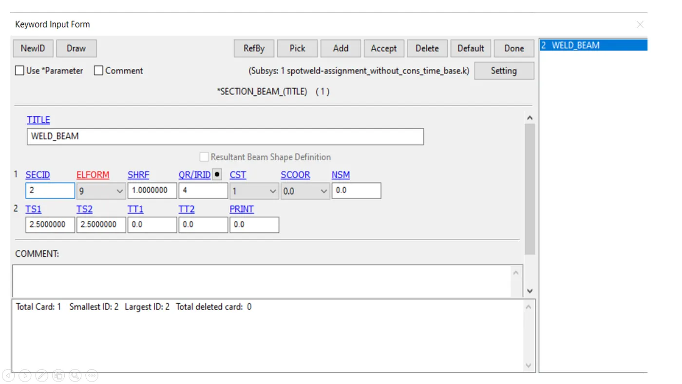
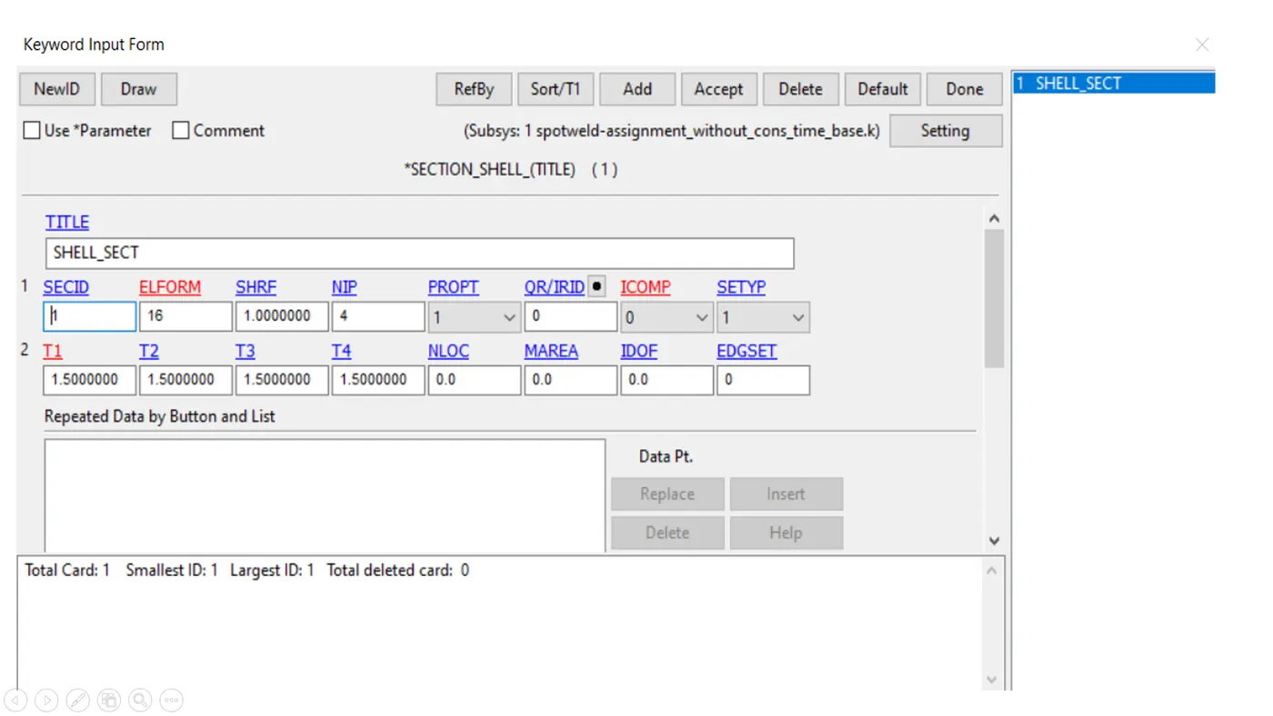
- The spotweld of beam is created by using the element generation option through element and mesh utility. For beam formulation ,the section property is assigned by using *SECTION_BEAM CARD. It is important to assign eement formulation (ELFORM)as 9 because MAT_SPOTWELD material card model only applies for ELFORM 9formulation.the cross sectional gives zero cross section area during the simulation. The beam thickness at both ends is given as 3mm.shell section also defined for metal sheets.
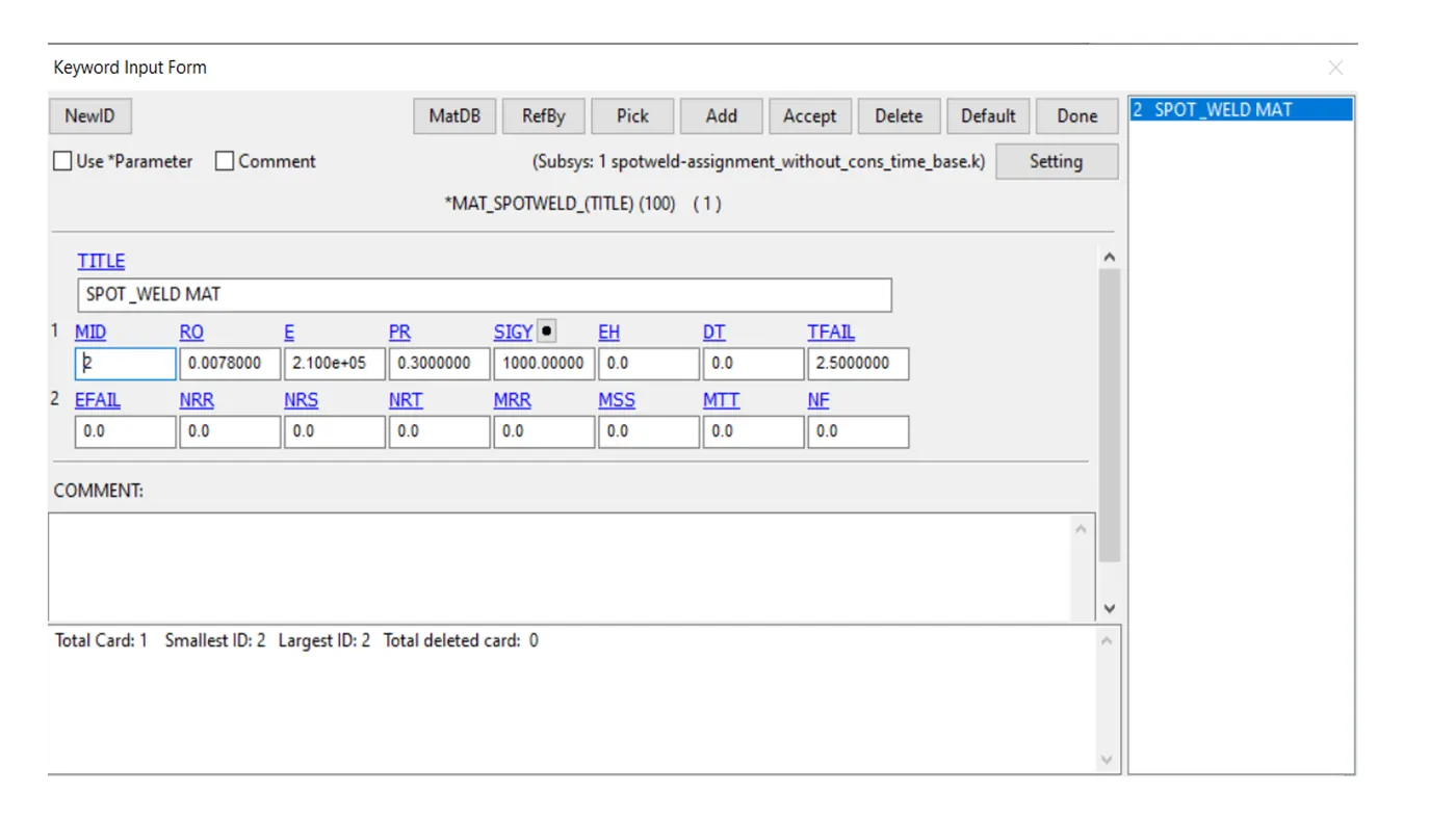
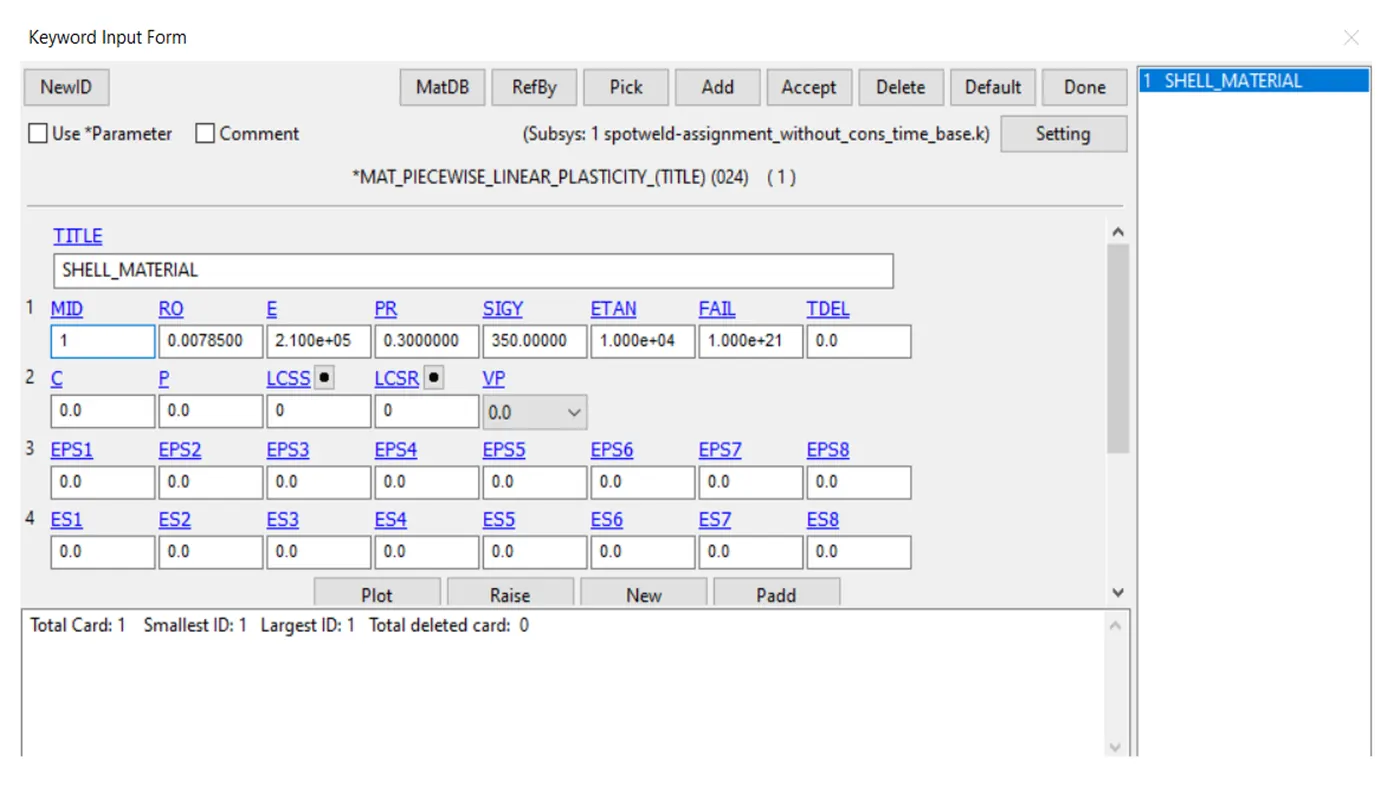
- The material property is defined by MAT_SPOTWELD card , the material properties are defined similarly to steel properties.the time dependent failure criteria is assigned.the spot weld fails at 2.5ms. other failure criteria such as effective plastic strain ,resultant stress,axial stress assigned very high values to consider only time dependent failure criteria.
Section shell
- MAT_024 OR MAT_PIECEWISE_LINEAR_PLASTICITY. this material model is the standard workhouse and is the recommended starting point for elastic -plastic deformation of metals and general plastics since it can also handle viscoelastic behaviour.
CONTACT INTTERFACE
AUTOMATIC_SINGLE_SURFACE
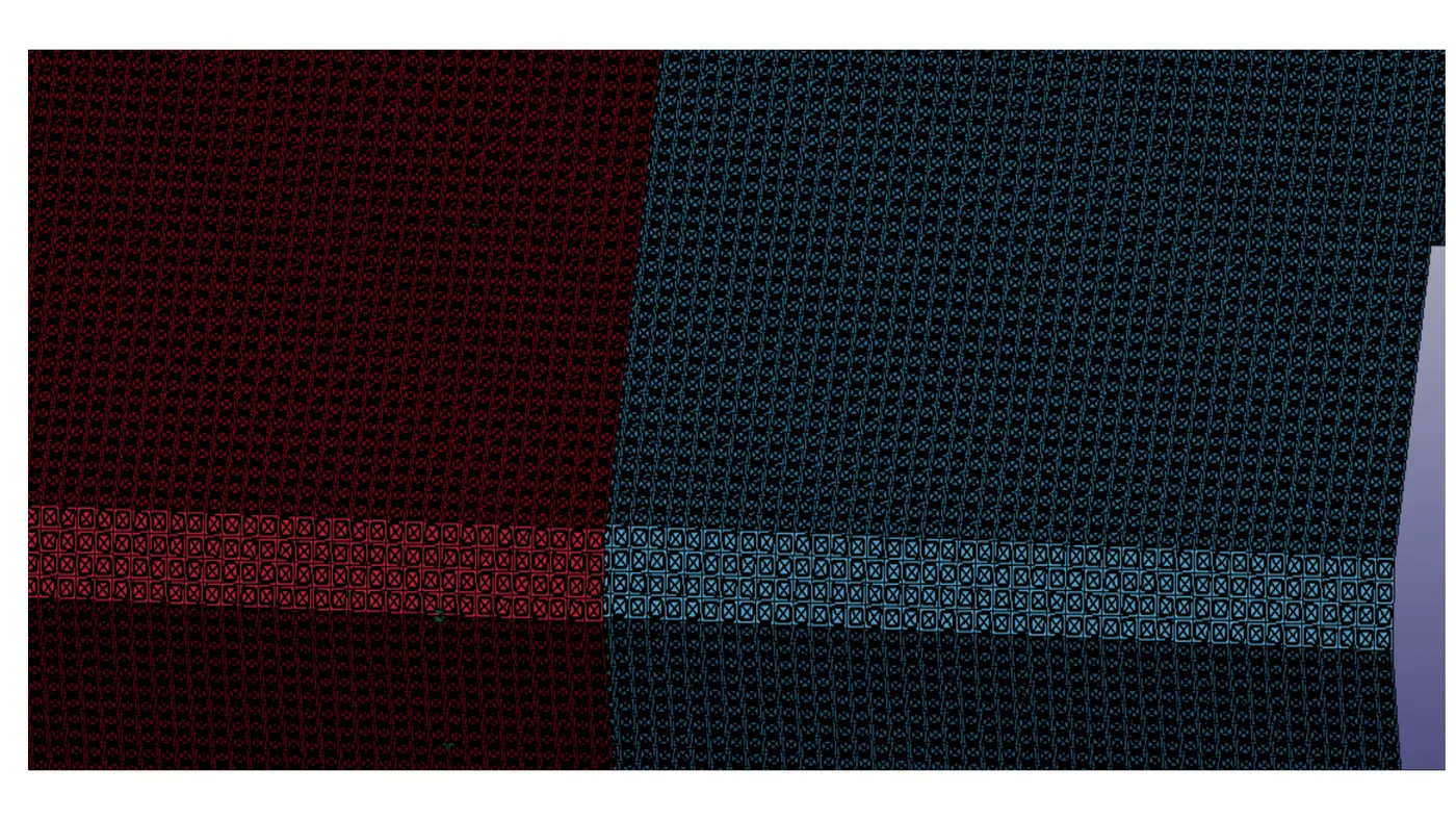
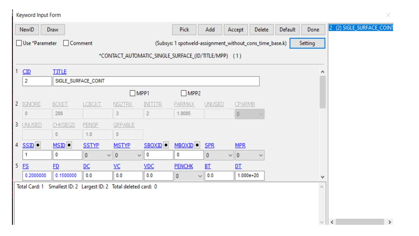
- This card can be used to specify contacts that could occur between the two shell components or the elements within. This can be achieved by creating a set_parts which contains both the top and bottom shell componets and assigning it to SSIDin the card while the SSTYPis set to 2.
TIED_SHELL_EDGE_TO SURFACE
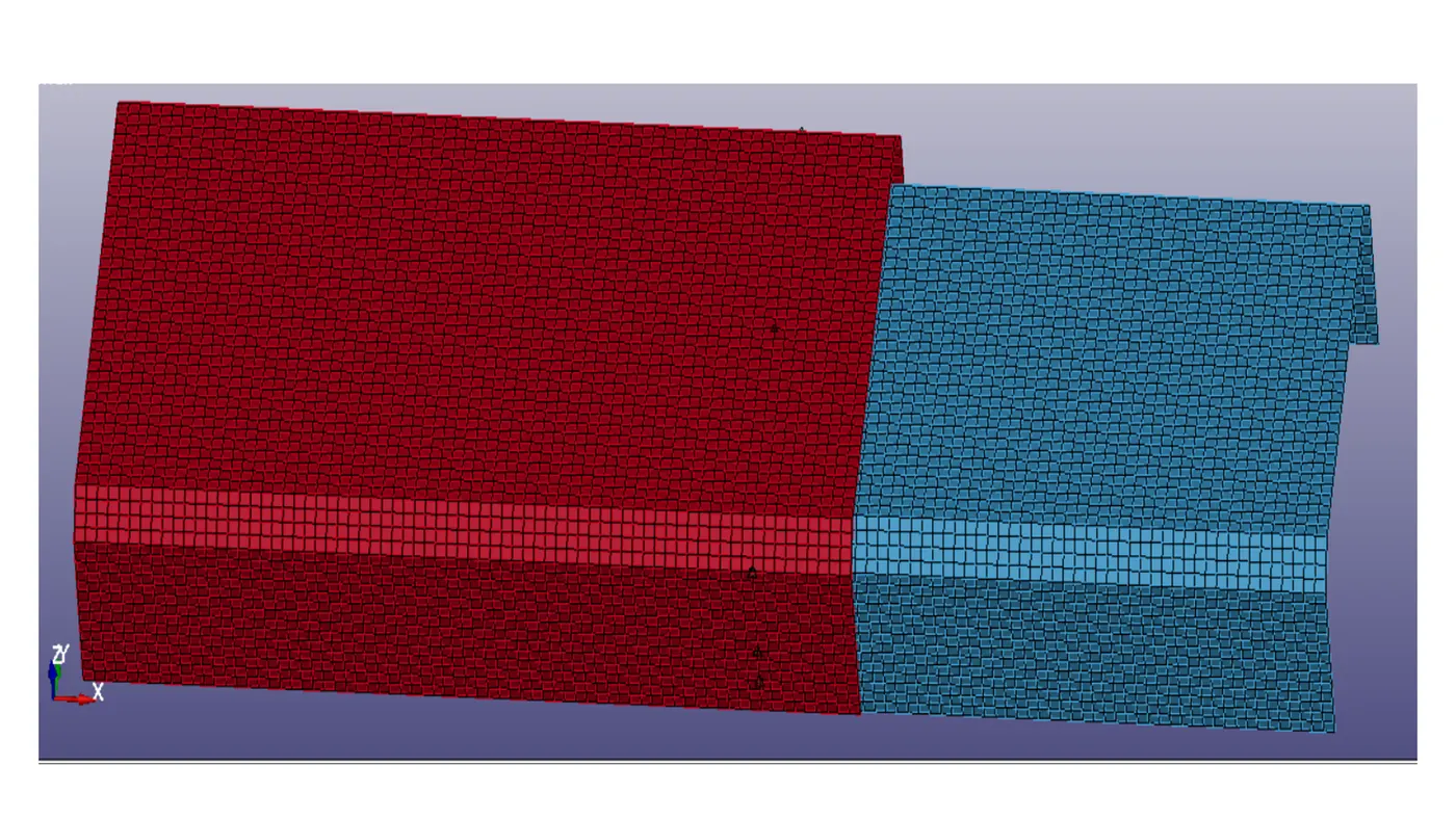
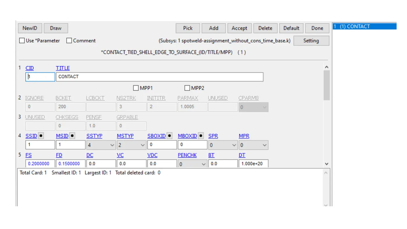
- In this of a beam element connected to the nodes of the shell surfaces ,we will use the CONTACT_TIED_SHELL_EDGE_TO_SURFACE card.here the slave elements are the nodes of the beam element and the master elements are the shell parts.
INITIAL VELOCITY
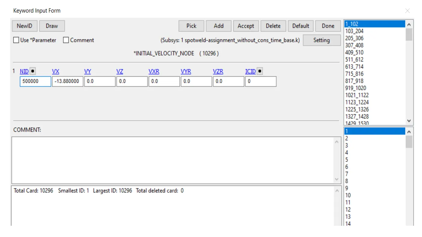
- in this model the crashing assembly ismade to hit the rigidwall at an impacing velocity 13.88 mm/ms.initila velocity card is used to apply velocity for crashing assembly in the direction of impact.
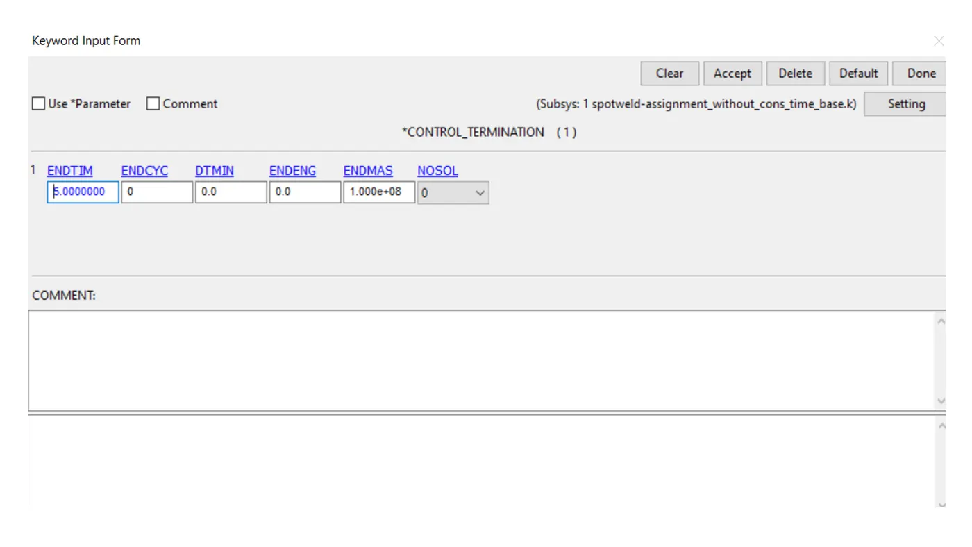
CONTROL_TERMINATION
- The keyword is used to specify the end time of the simulation which in this case set to 5 ms.
DATABASE
- This keyword specifies the output parameters that need to be extracted during the simulation.
BINARY_D3PLOT
- we specify a time interval of 0.5 which represents that for each 0.5 ms the output data of the analysis is written on the d3plot.
ASCII
- GLSTAT- globel statistics involving IE, KE,Hourglass energy etc.
- SLEOUT- sliding interface energies
- SECFORCE -cross-sectional forces
- NODOUT – Nodal properties like displacement ,acceleration etc.
- SWFORCE – spotweld nodal constraint reaction forces.
POST PROCESSING
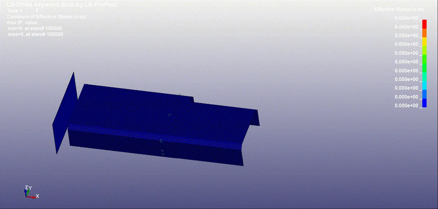
VONMISES
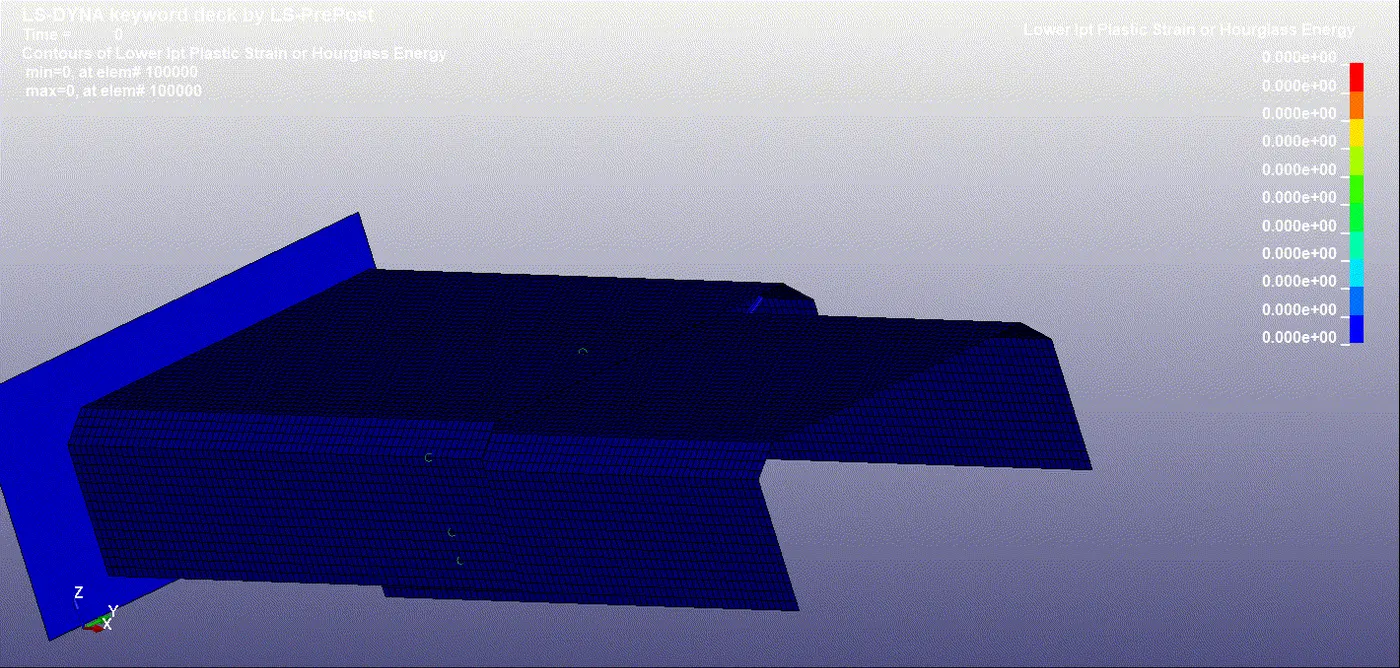
HOURGLASS ENERGY
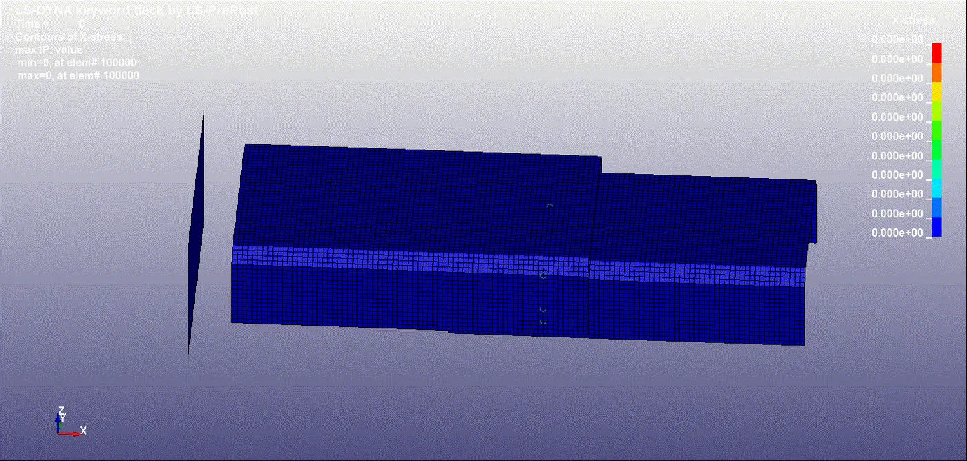
x accleration
ENERGY
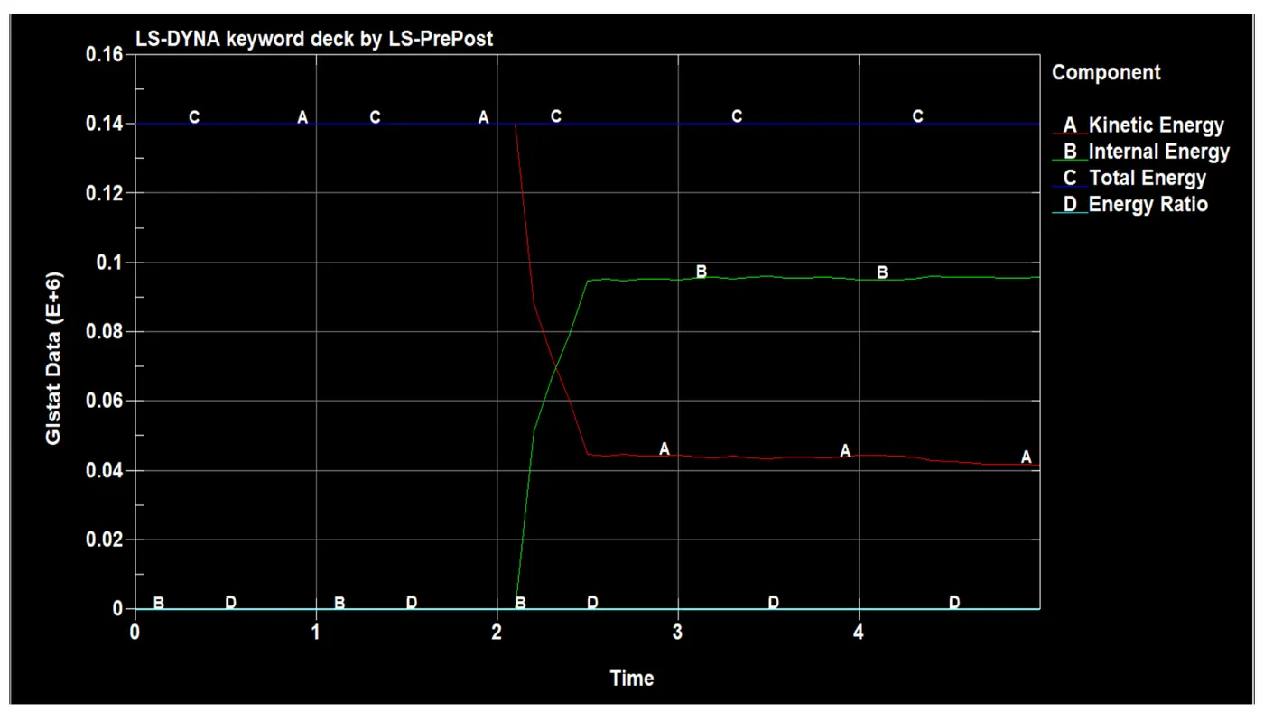
- In graph IE and KE time 0 the energy also 0 which indicate there no energy dissipation between and impactor but time 2.5 there is contact happening between the plate and wall. So the energy dissipation occur .so that internal energy sheet is increased after some time the it come the low value due to the sheet bounce and no contacting between them and also the stree is evenly distributed around the parts.
ACCELERATION
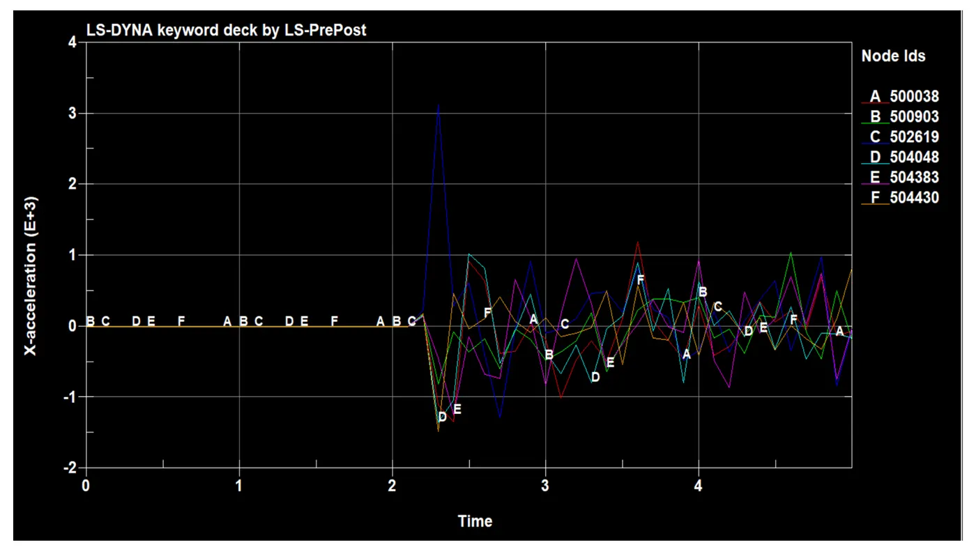
- Acceleration of the indicated node during the impact with the rwall and part the acceleration of the node is 502619 only inverse other node is getting down it why happened mean.when the part hiting the wall the next time step the part will rebounce that means acceleration nodes is retardation which means the deacceleration.in the next time step th blue part is moving forward along with the red part ,so the acceleratin of the node with indicated the zig zag manner after failing the node at time of 2.5ms the acceleration of the nodes are present .the maximum acceleration 3130 mm/ms^2 on the other hand -1478.3mm/ms^2 is deacceleration of the nodes.
AXIAL FORCE
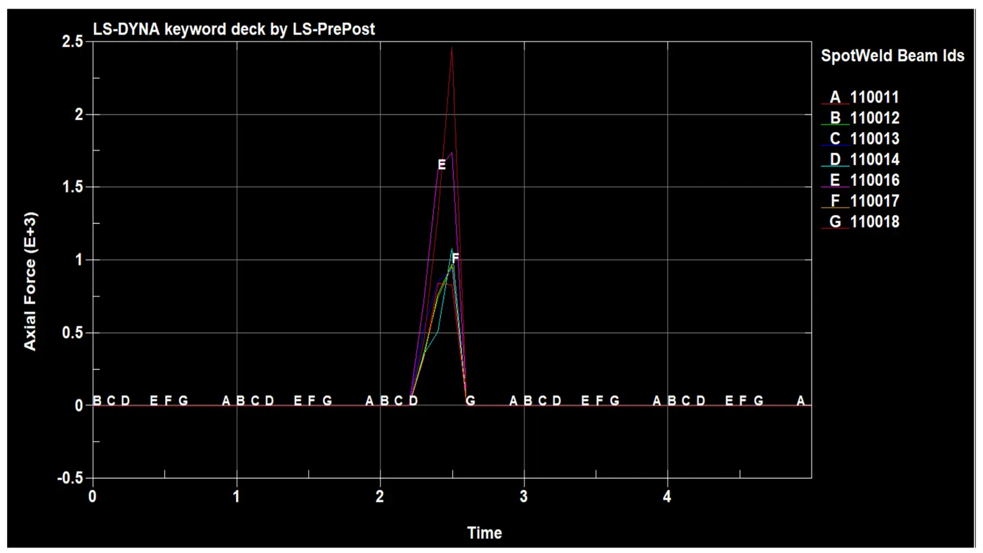
- the above time base spotweld beam fail.when the part hit on the wall at time of 2.1 the stress increases.at the same time the weld axial force also increase based on the next time step and velocity.but the time of 2.5 the stress will be on there part due to the high impact between rwall and part the force between the weld part is zero.
SHEAR FORCE
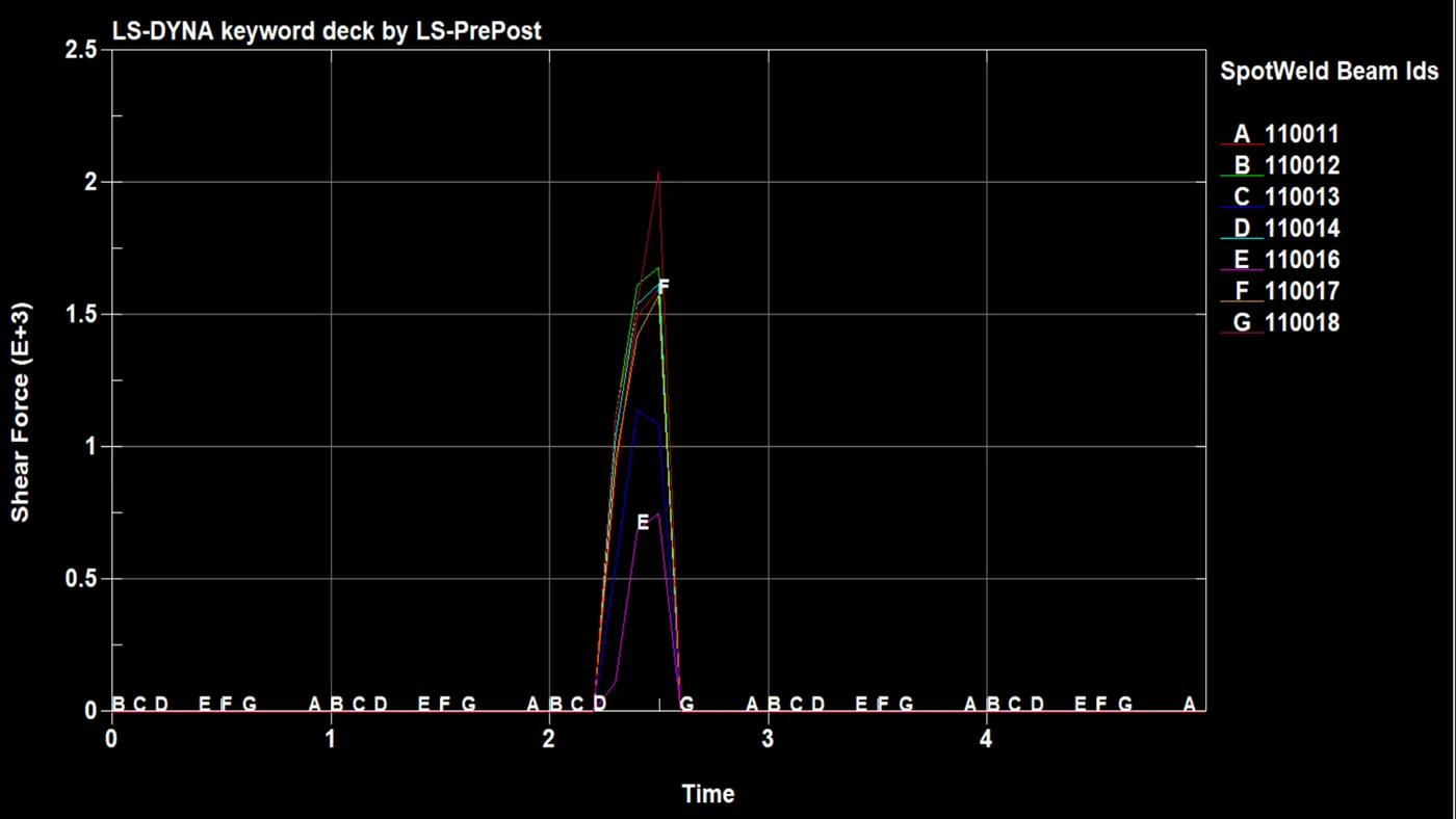
- shear force of the solid spotweld linearly increases till the Tfail card and at the time step it suddenly drops to zero and it is constant till the simulations ends.
SPOT WELD BY SOLID ELEMENT FORMULATION
The material card is not changed and used as it is to assign material properties tosspot welds defined by soild element formulation. The spot weld of the soild element is created by using element generation option through element and mesh utility as discussed earlier. So section properties are defined by using SECTION_SOLID CARD ,here solid section it is important to assign element formulation (ELFORM) as 1 because MAT_SPOTWELD material model only applies ELFORM 1 formulation.
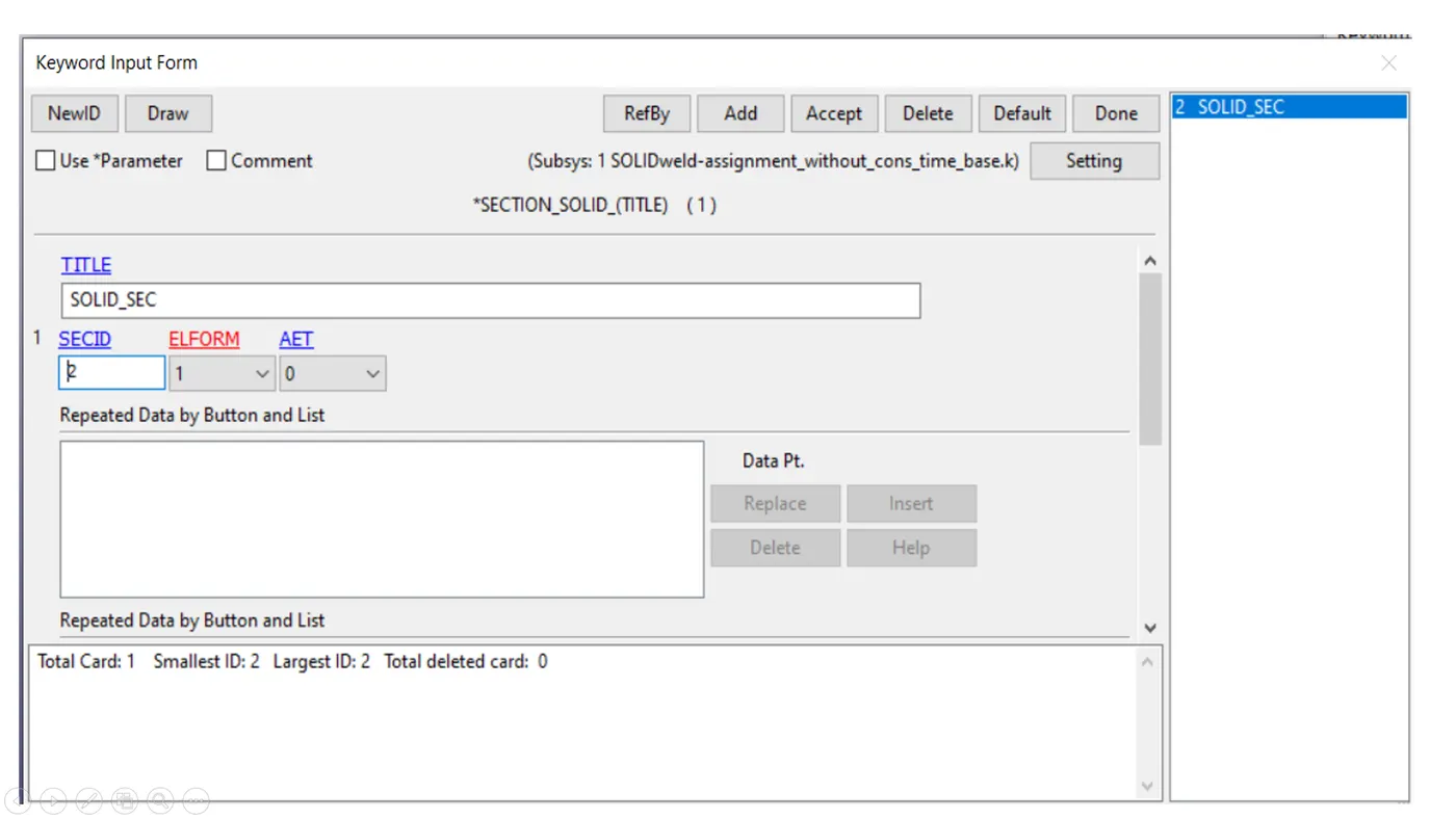
contact
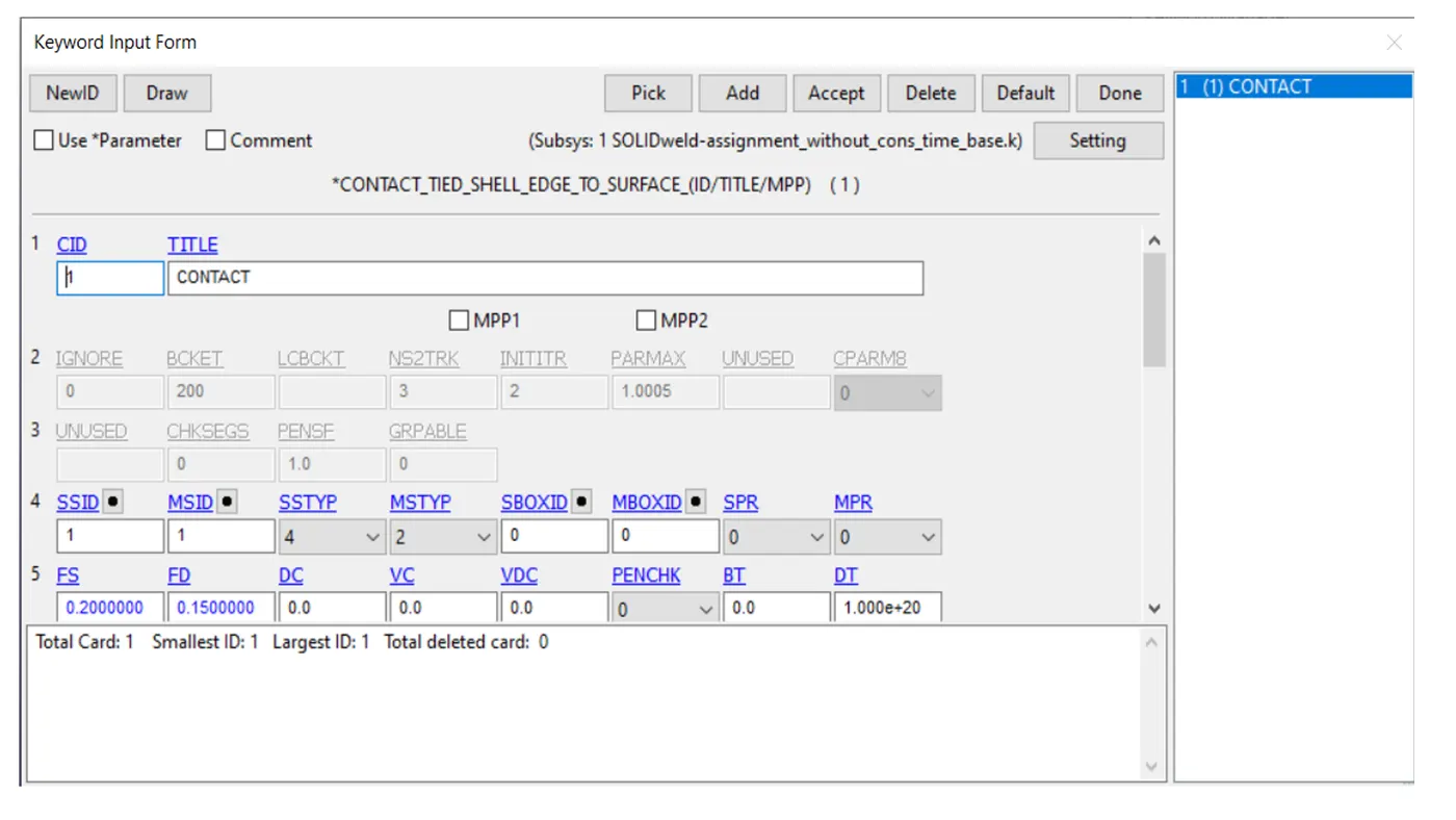
the desired contact thype of spot weld defined by solid element CONTACT_SPOTWELD. the master and slave segmentare modelled in a similar way
All other steps are kept similar to the challenge 4 .in addition ,swforc data base card is added which gives the nodel constraint reaction forces for spot welds. Through energy plot for the system, it can be seen that there is a significant increase in hourglass energy.so there are few methods to control the hourglass energy like changing element formulation, number of integration point, adding hourglass control etc .the control hourglass card is used to control the hourglass energy.
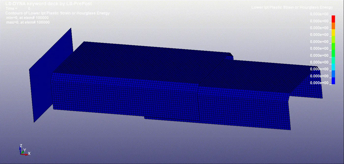
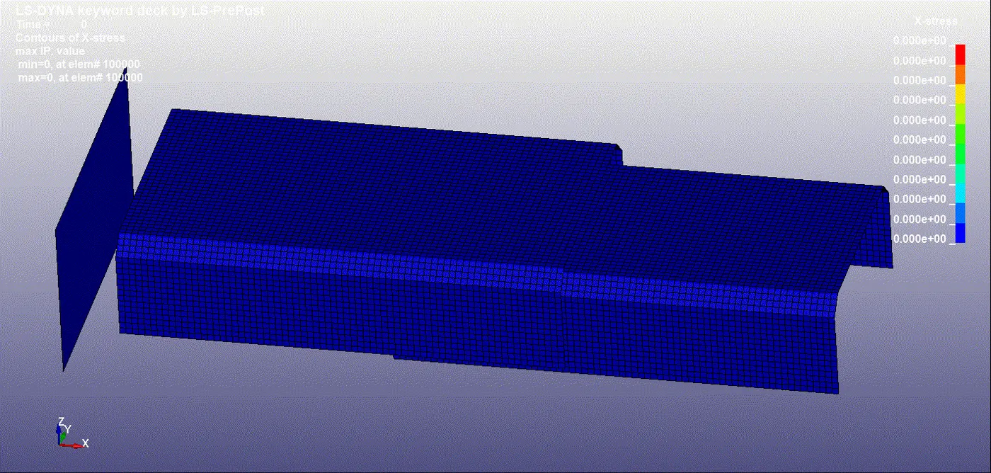
VONMISES
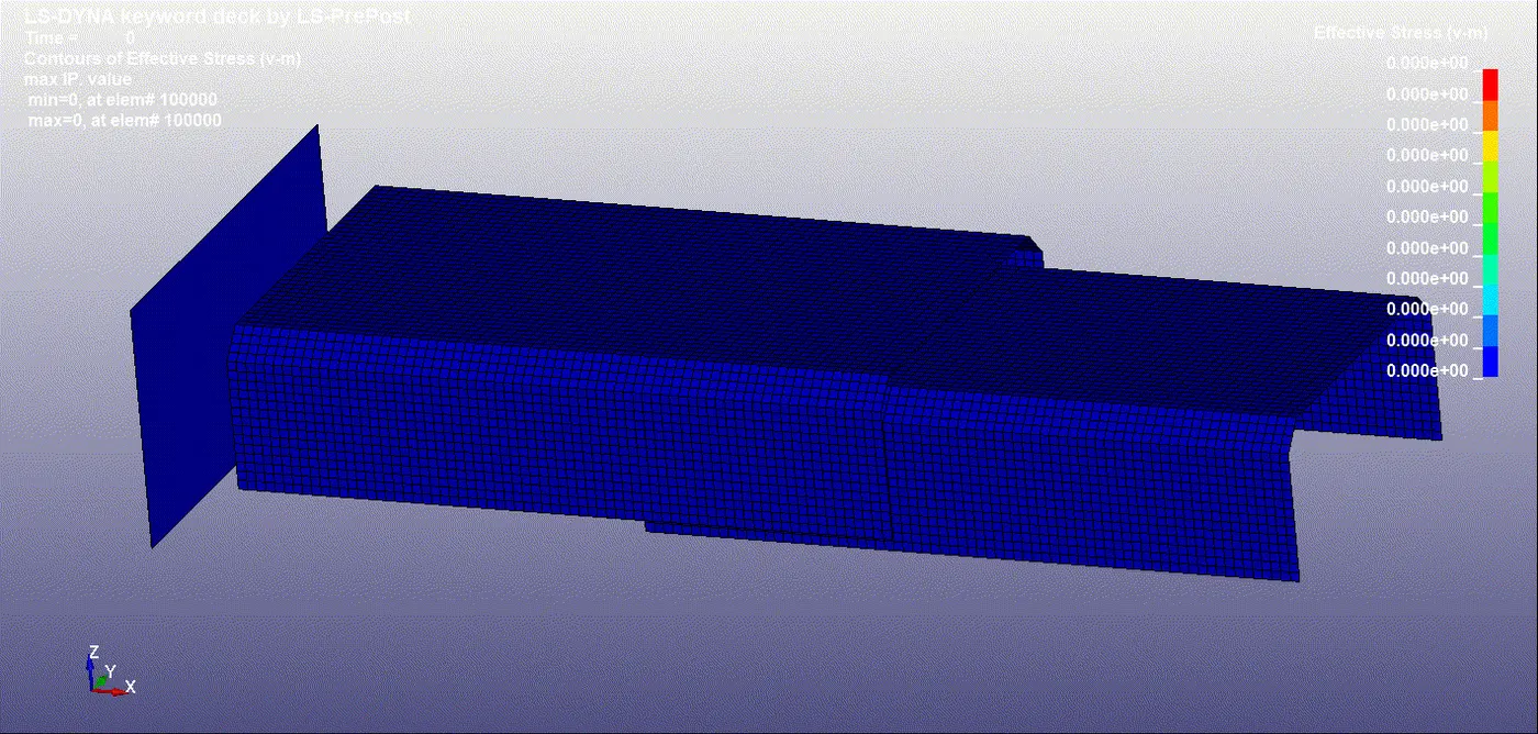
HOURGLASS ENERGY
x accleration
ENERGY
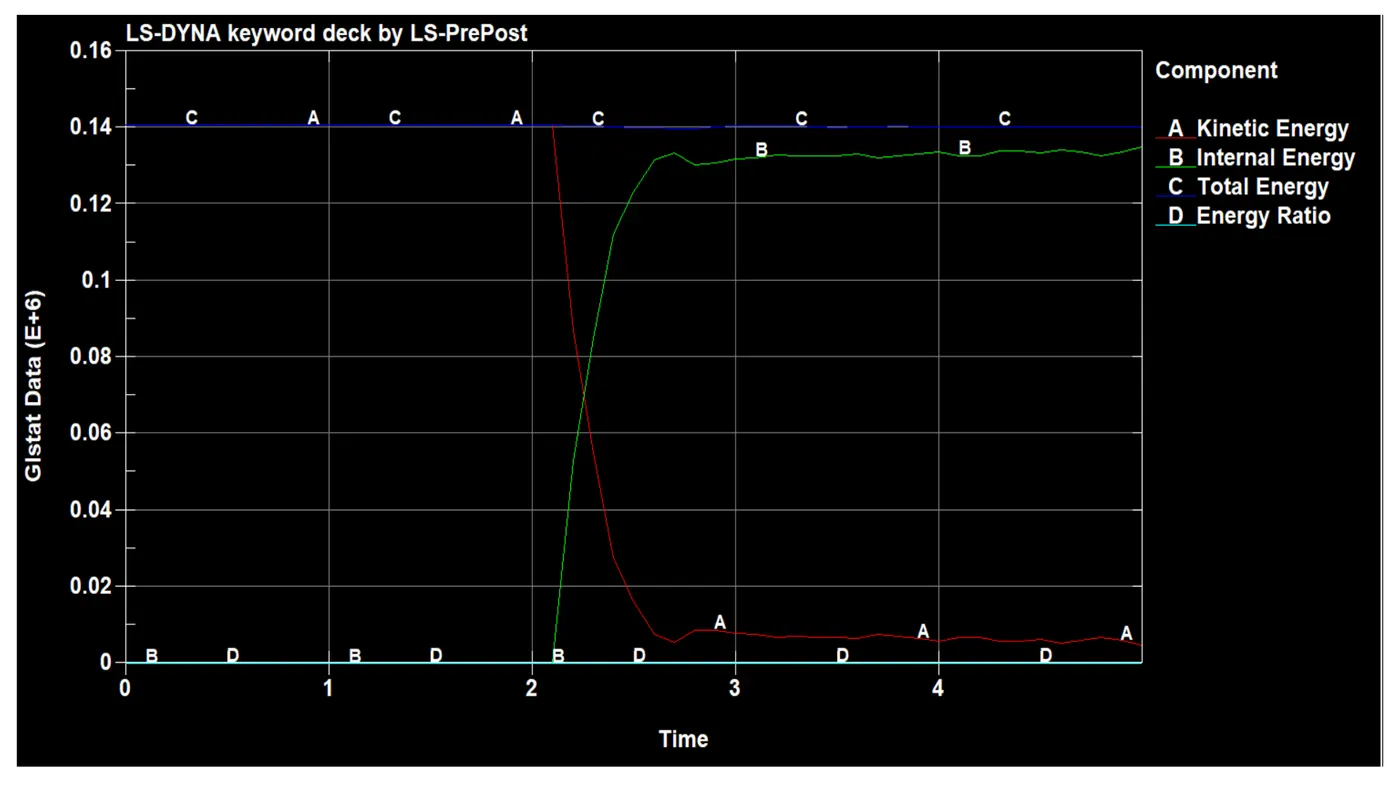
- in the graph IE nad KE time 0nthe energy also 0 which indicate there no energy dissipation between phone and impacter buttime 3.2 there is contact hapening between the wall and componet so that the energy dissipation occur so that internal energy of the componet increased after some timethe it come the low value due to the component is bounce and no contacting between them and also the stress is evenly distributed around the parts.
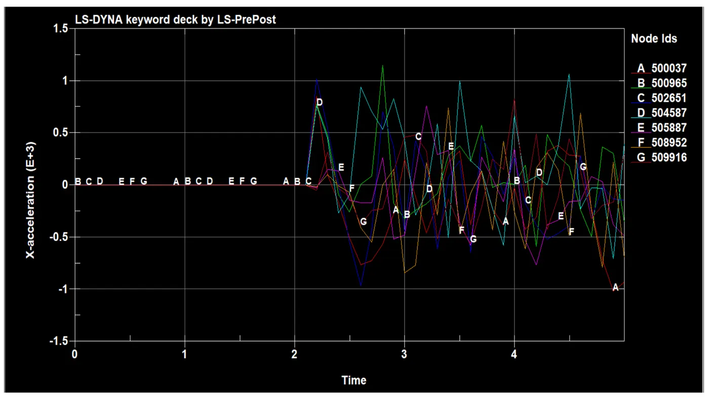
ACCELERATION
-
the acceleration of the spotweld connection element at the time 2.1 the acceleration element starts after hit the part the part is come back at the time the part is highly deform sa seen .the acceleration of spot weld area undergone to the de acceleration shows that the graph is zig zag mannaer time fail in 2.5ms the weld get fail but the acceleration of the weld element id not get rest under inertia force so that the graph after the 2.5 ms also still zigzag mannaer the maximum acceleration is 1305.5mm/ms2.
AXIAL FORCE

the soild walls is much stronger than the spot weld .the part hitting on the wall at the time the stress of the part is 417n/mm2. at the time there is no weld are not failed due to the weld is solid element and there material property in the t=2.5 the stress of part is more high 1615.81N/mm2. which indicate more stress element is stretch together with help of solid joint and the time t=2.5 the stress of the part is 847.376N/mm2.the maximum axial force is 377908N at time of 2.5ms in the weld id is 110025.
SHEAR FORCE
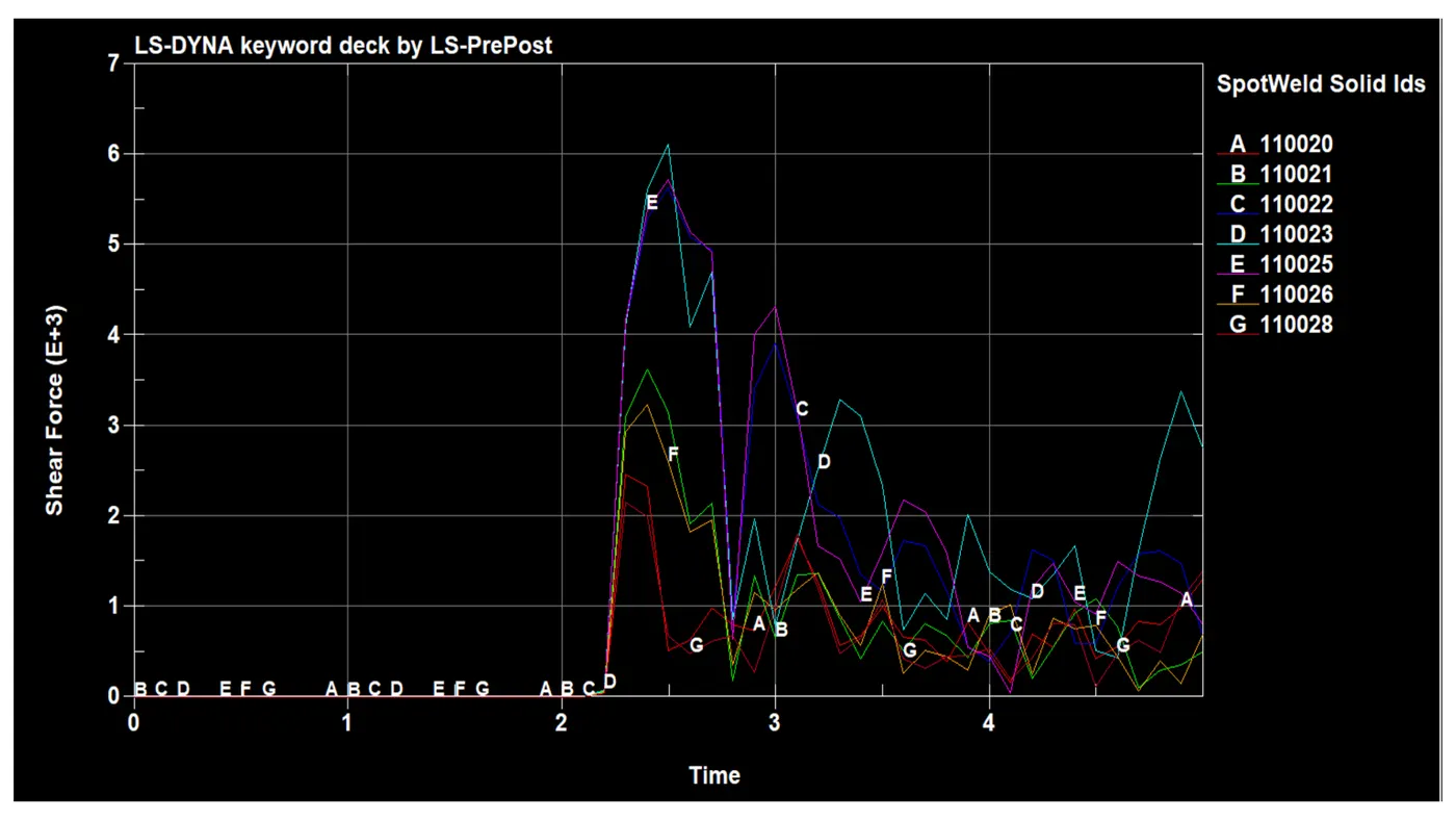
shear force of the solid spotweld linearly increases till the Tfail card and at the time step it suddenly drops to zero and it is constant till the simulations ends.
CONCLUSION
The spot welds have been modelled by using beam and solid elements separately. the present spot weld model can be calibrated to actual spot weld by assigning known failure criteria such as plastic strain, axial force, resultant force etc from the experimental data.
The solid element gives a better representation of the actual spot weld connection.
The main difference between both modelling approaches is the contact definition. contact tied shell edge to surface is used for beam element formulation and contact spotweld is used for solid element formulation
G link : https://drive.google.com/file/d/1zoatAQ8vuLeOQhZGUG82LWegmAdLm-qF/view?usp=sharing