Week - 5 - Modelling Spotwelds
SPOT WELD SIMULATION
INTRODUCTION
BIW (Body-in-white) is a frame of the vehicle, composed of sheet metals, which is integrated through various joints such as spot weld, seam weld, arc weld, brazing, hemming, adhesive bonds, etc., All these joints together are responsible for the vehicle’s integrity and dimensional accuracy. Among all these joints, conventionally, spot weld is the most preferred type of weld. It is because of its low cost, fast operation, and economic characteristics. Also, because spot welds do not use any filler material, it does not increase the vehicle's weight. Typically, a BIW has 3000-5000 resistance spot welds . Now, because, practically, spot weld plays so much importance in BIW, it also has that much importance in virtual testing. Spot weld modeling and use of its formulation vary industry-to-industry. However, the usual way of modeling it is tried here, in this work.
OBJECTIVE
- To model spotweld using beam and solid element.
- To run a crash test on joined parts.
- To compare the axial and shear force generated in both cases.
PROCEDURE
Pre-processing
For creating spot-welds, two discretized plates were available as shown in fig. 1. On those plates, 3-7 spot-weld had to create in the indicated line. In the first case, the weld had to design with a beam element, and in another case, it had to design with a solid hex element.
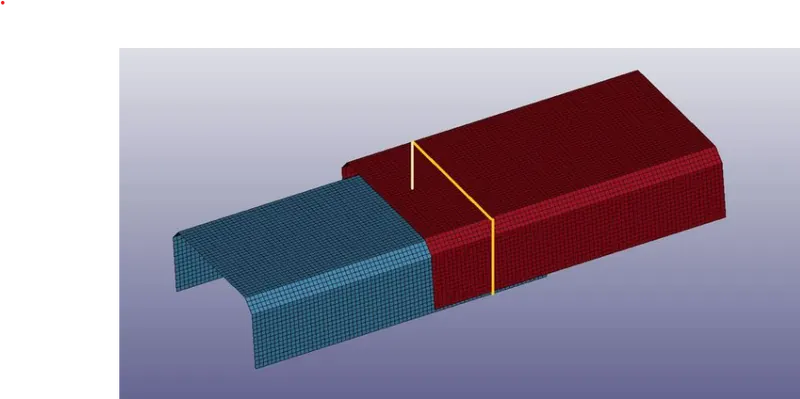
Figure 1: Two parallel discretized plates model, for spot welding.
Case I
Creating Beam Elements
The first step in case 1 was to create the beam elements. Using Element and Mesh → Spot Welding, a beam element was created, joining two nodes of the two plates, as shown below. In the figure, the beam elements are shown as white-colored elements. This is how 4 spot weld beam elements were created between two plates.
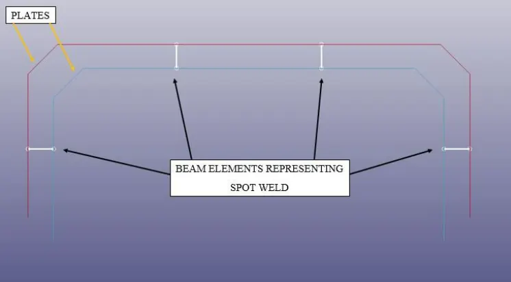
Figure 2: Beam element created to use them as spot weld connection.
Creating Material Card
Using Keyword Manager, in the MAT section, 100-SPOTWELD was selected as the material card. In this work, [gm mm ms] unit system was followed, according to which density of steel is equal to 7.85e-3, Young’s modulus is equal to 210e+3 MPa, Yield Stress is equal to 250 MPa.
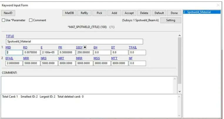
Figure 3: Spot weld material card, MAT-100-SPOTWELD.
In the card, TFAIL is the time at which the material should fail. It is used when experimental data is available which ensures when the spot weld gets failed. But because it was unavailable, it was ignored. Similarly, the other parameters were defined with larger values, so that we can find out those values while the spotweld gets failed, during simulation. This procedure is followed only because of the unavailability of the experimental data, and the case that was being dealt with. Depending on different cases, these parameters were provided with specific values. For example, if it is already known that at what time the spot gets failed, and how much plastic strain gets generated at that time, then those values can be provided to those respective parameters.
Similarly, another material card was created for the two plates. For the plated, using Keyword Manager, MAT → 001-ELASTIC card was chosen. And the steel material properties were provided to it. After creating the card, it was assigned to the two plates.
Creating Section Card
When a beam element is used as a spot weld connection, according to the LS-DYNA manual, it only works with element formulation 9. Using Keyword Manager, SECTION → BEAM was selected, and in that, ELFORM was selected 9, as can be seen in the figure below. And, TS1 and TS2 are the thickness of the beam in s-direction, which is given equally to 2 mm.
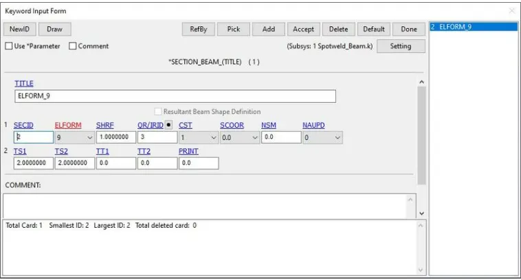
Figure 4: SECTION_BEAM card to apply spot weld properties to the beam. Similarly, another section card was created for plates. For that, using Keyword Manager, SECTION → SHELL was selected, and in that, the thickness was given equal to 1.5 mm, with ELFORm equal to 16, which allows fully integrated shell elements.
Contact Definition
Now, when the modeling of a spot weld is done, next important thing is to assign the contact. When the contact has to be assigned for spot weld, the parts which are getting attached are always masters, and the spot weld is always slaves. So, to assign it as such, firstly, a set of parts and spot weld was required. Using the Entity Creation → Set Data, two sets were created, each of plates and nodes of welds.
Then using Keyword Manager → All → CONTACT → TIED_SHELL_EDGE_TO_SURFACE was selected. In that card, the two sets viz. part set of plates, and nodes set of spot weld beams were selected as master and slave respectively.
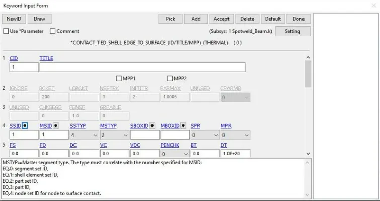
Figure 5: TIED_SHELL_EDGE_TO_SURFACE contact for plates and spot weld elements.
It is also required to create the AUTOMATIC_SINGLE_SURFACE contact for the entire model, for the case, after the impact no parts should penetrate each other. So using, Keyword Manager → All → CONTACT → AUTOMATIC_SINGLE_SURFACE was selected, and in that card, only the slave set is given as nodes of the entire model.
Boundary Condition
Once the model is ready with the material, elemental formulation, and contact, it is ready to define the boundary condition. In the simulation, the crash test condition was required. Therefore, in the boundary conditions, a rigid wall was created, as can be seen in figure 6 below. And to the plates, an initial push or an initial velocity of 50 kmph or 13. 89 mm/ms was provided.
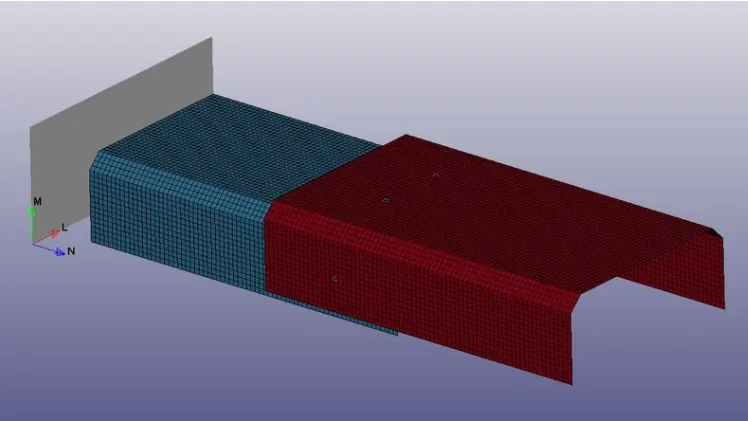
Figure 6: Rigid wall was created to make a crash environment.
Next, to the other plate, an initial velocity of 13.89 had to provide. To do that, at first, a set of nodes from the top plate was created. Then using Keyword Manager → All → INITIAL → VELOCITY card, an initial velocity of 13.89 mm/ms was provided to the top plate in a constrained direction.
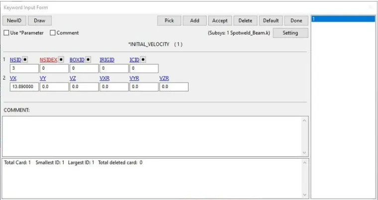
Figure 7: Initial Velocity Card.
Control Card
The control cards are required to control the simulation process. In this, the most essential card that is required is the termination card. It is used to define the termination time of the simulation. The termination time was set to 10 ms. It was defined using the Keyword Manage → All → CONTROL → TERMINATION. In that card, the ENDTIM or the end time was given as 10.0.
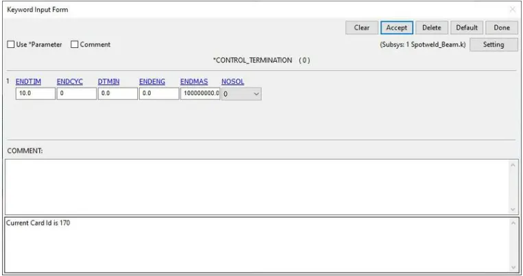
Figure 8: Card to define the termination time.
Database Cards
Database cards are required to command the software that what files are required in the output. In this simulation, binary_d3plot was required to generate. So using Keyword Manager → All → DATABASE → BINARY_D3PLOT card, binary data was requested at every DT equal to 0.1 ms.
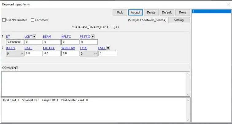
Figure 9: BINARY_D3PLOT card.
In the results, since the energy behavior is always the part of the concern, in Keyword Manager → All → DATABASE → ASCII_option, a GLSTAT card was requested. Along with that, SWFORC was requested to get the forces generated on the spot-welds. Also, NODOUT was requested to get the nodal displacement/velocity/acceleration data.
The NODOUT card does not workout until a DATABASE_HISTORY_NODE is activated. So, using Keyword Manager → All → DATABASE → HISTORY_NODE, a history of four nodes of the beam elements was requested.
Once done with defining the keywords, the next essential thing is to check that if any errors are present in it. Therefore, using the Model Checking, the keywords were checked for errors and warnings. When no errors were found, the simulation was run.
After completing defining all the keywords, the model was saved in .k format.
Case II
Creating Solid Spot Weld Elements
In case II, the only difference is that the solid element was now used instead of the beam element. Solid elements are used in the case when visual of stress distribution and displacement is important. Now, to create the solid element, Element and Mesh → Element Editing was selected, using which 4 solid spot welds were created, as can be seen in the figure below.
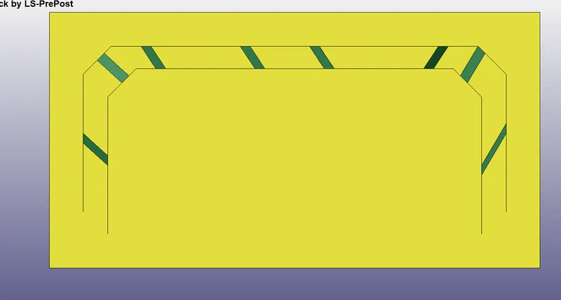
Figure 10: Solid Hexa spot weld elements created between plates.
Creating Material Card
The material was selected as earlier. Using Keyword Manager, in the MAT section, 100- SPOTWELD was selected as the material card. In this work, [gm mm ms] unit system was followed, therefore, according to that density of steel is equal to 7.85e-3, Young’s modulus is equal to 210e+3 MPa, Yield Stress is equal to 250 MPa.
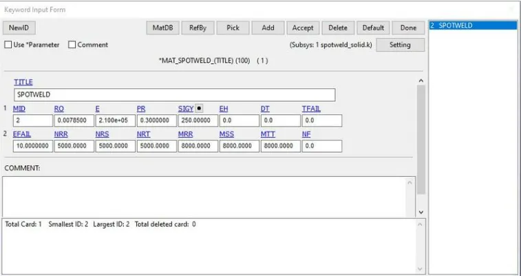
Figure 11: Spot weld material card, MAT-100-SPOTWELD.
Similarly, another material card was created for the two plates. For the plates, using Keyword Manager, MAT → 001-ELASTIC card was chosen. And the steel material properties were provided to it. After creating the card, it was assigned to the two plates.
Creating Section Card When a solid element is used as a spot weld connection, according to the LS-DYNA manual, it only works with element formulation 1. Using Keyword Manager, SECTION → SOLID was selected, and in that, ELFORM was selected 1, as can be seen in the figure below.
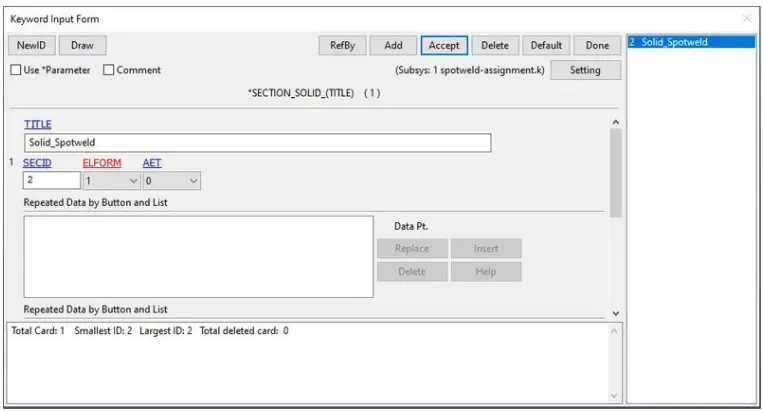
Figure 12: Section card for solid spot weld elements. Similarly, another section card was created for plates. For that, using Keyword Manager, SECTION → SHELL was selected, and in that, the thickness was given equal to 1.5 mm, with ELFORm equal to 16, which allows fully integrated shell elements.
Contact Definition
Now, when the modeling of a spot weld is done, next important thing is to assign the contact. When the contact has to be assigned for spot weld, the parts which are getting attached are always masters, and the spot weld is always slaves. So, to assign it as such, firstly, a set of parts and spot weld was required. Using the Entity Creation → Set Data, two sets were created, each of plates and spotweld nodes.
Then using Keyword Manager → All → CONTACT → SPOTWELD was selected. In that card, the two sets viz. part set of plates, and nodes set of spot weld elements were selected as master and slave respectively.
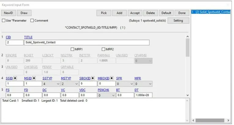
Figure 13: SPOTWELD contact for plates and spot weld elements.
It was also required to create the AUTOMATIC_SINGLE_SURFACE contact for the two plates, for the case, after the weld failure the plates shouldn’t penetrate in each other. So using, Keyword Manager → All → CONTACT → AUTOMATIC_SINGLE_SURFACE was selected, and in that card, only the slave set is given as the two parts.
Boundary Condition
Once the model is ready with the material, elemental formulation, and contact, it is ready to define the boundary condition. The same boundary condition, as in the earlier cases, was used in this case. Since the crash test condition was required, therefore, in the boundary condition, a rigid wall was created, and to the plates, an initial push or an initial velocity of 50 kmph or 13. 89 mm/ms was provided.
Control Card
The control cards are required to control the simulation process. In this, the most essential card that is required is the termination card. It is used to define the termination time of the simulation. The termination time was set to 10 ms. It was defined using the Keyword Manage → All → CONTROL → TERMINATION. In that card, the ENDTIM or the end time was given as 10.0.
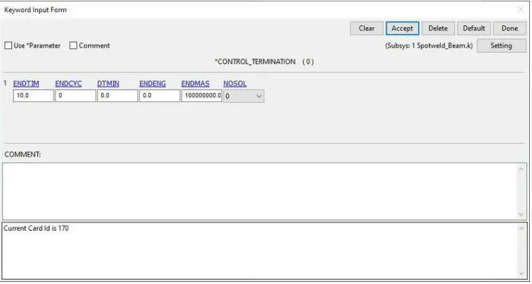
Figure 14: Card to define the termination time.
Database cards
Database card are required to command the software that what files are required in the output. In this simulation, binary_d3plot was required to generate. So using Keyword Manager → All → DATABASE → BINARY_D3PLOT card, binary data was requested at every DT equal to 0.1 ms.
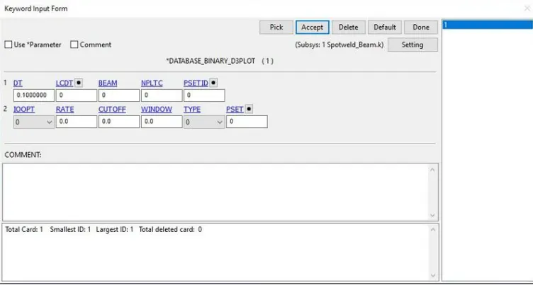
Figure 15: BINARY_D3PLOT card.
In the results, since the energy behavior is always the part of the concern, in Keyword Manager → All → DATABASE → ASCII_option, a GLSTAT card was requested. Along with that, SWFORC was requested to get the forces generated on the spot-welds. Also, NODOUT was requested to get the nodal displacement/velocity/acceleration data.
The NODOUT card does not workout until a DATABASE_HISTORY_NODE is activated. So, using Keyword Manager → All → DATABASE → HISTORY_NODE, a history of four nodes of beam element was requested.
Once done with defining the keywords, the next essential thing is to check that if any errors are present in it. Therefore, using the Model Checking, the keywords were checked for errors and warnings. When no errors were found, the simulation was run.
After completing defining all the keywords, the model was saved in .k format.
Solving
When the model is all set with material, element formulation, contacts, boundary conditions, and simulation control setup, the model is ready for the simulation. To run the model, the model was first saved in .k format. Using the LS-Run application, the .k file was imported to it, and run the file. The run terminated normally.
Post-processing
Case I
The intent of performing a simulation focus was to check the axial and shear force that is generating on the spot weld element, in both cases. The von mises contour can be seen in fig. 15 below, for the case of spot weld with beam elements. The stress spots can also be seen on the upper plate, which is induced due to the presence of spot weld beam elements.
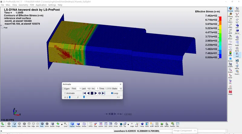
Figure 16: Von mises contour of the model at 1.099 ms.
Fig. 17 shows the axial force generated on the beam elements. The maximum force of around 789 N can be seen in the plot.
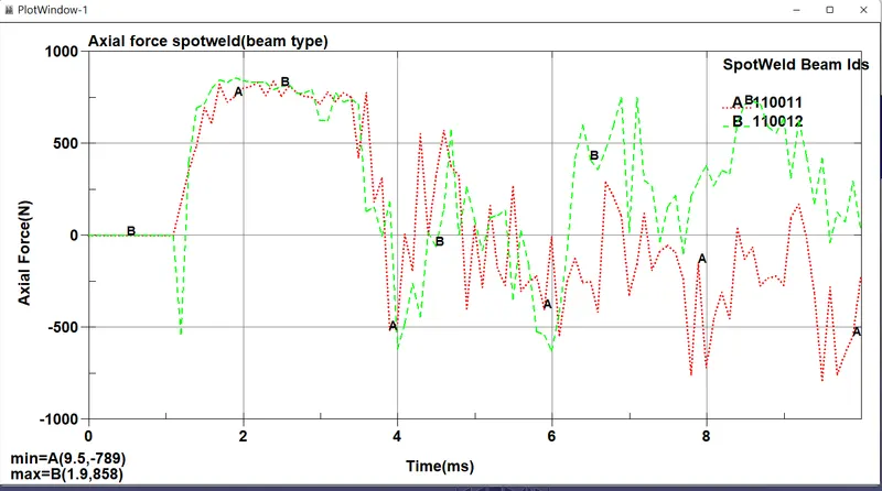
Figure 17: Axial force on beam elements. The beam was of tubular cross-section, had an outer diameter of 2 mm, and inner was 0. Collectively, it had an area of cross-section of 12.56 mm. sq. Theoretically, max. tensile stress came on one beam was equal to the max. force of 789 N divided by area, equal to 12.56 mm. sq. Thus, the maximum tensile stress induced on a beam was 71.6 MPa, which is a much lower value than the tensile yield strength value of steel material (Sys of Steel = 250MPa).
Fig. 18 shows the shear force coming on the beam elements. Like earlier, shear stress coming on the beam element was equal to 550 N divided by 12.56 mm. sq. of cross-section, which is equal to 43.8 MPa, which is also much lower than the shear yield strength of the steel material (Sss of Steel =150MPa(0.6*Sys)).
Thus, the spot welds shouldn't fail in this criteria of boundary conditions applied.
(Note: Parameters values were taken arbitrarily for educational purposes).
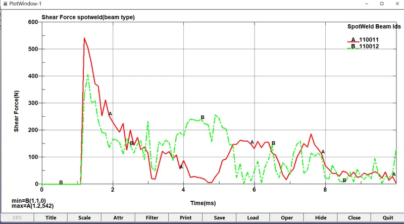
Figure 18: Shear force on beam elements.
Case II
In case 2, the area of interest was to check the von-mises stresses on the spot weld elements and to check the axial and shear force that is generating on it. The von mises contour of the model can be seen in fig. 19 below, for the case of spot weld with solid elements. The stress spots can also be seen on the upper plate, which is induced due to the presence of spot weld solid elements.
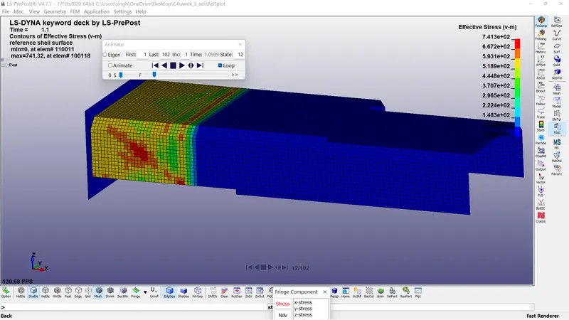
Figure 19: Von mises contour of the model at 1.1ms. Spot welds are modeled with solid elements when the stresses behavior in the weld nugget requires visual inspection. The kind of simulation that was run indicates that the weld nugget was not subjected to axial, but the shear force. Thus, the reason behind failure is primarily the shear force.
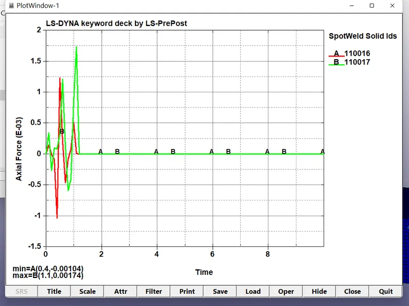
Figure 20. Axial force on solid spot weld elements.
The maximum force of around 0.00174 N can be seen in the plot, in both tension and compression. The nugget was of rectangular cross-section, with a length of side equal to 1.5 mm. Collectively, it had an area of cross-section of 2.25 mm. sq. Theoretically, max. tensile stress came on one beam was equal to the max. force of 0.00174 N divided by area, equal to 2.25 mm. sq. Thus, the maximum tensile stress induced on a beam was 222.22 MPa, which is close to the tensile yield strength value of steel material (Sys of Steel = 250MPa).
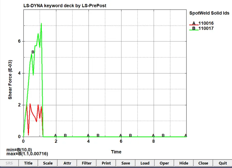
Figure 21: Shear force on solid elements.
Fig. 21 shows the shear force coming on the solid elements. In the figure, it can be observed that the force in the shear direction is at a larger magnitude compared to axial force. Like earlier, theoretically, shear stress coming on the solid element was equal to around 1.65e+3 N or 1650 N, divided by 2.25 mm. sq. of cross-section, which is equal to 733.33 MPa, which is greater than the shear yield strength of the steel material (Sss of Steel = 150MPa (0.6*Sys)). Thus, the spot welds should fail in this criteria of boundary conditions applied. (Note: Parameters values were taken arbitrarily for educational purposes).
CONCLUSION In this work, two cases were analyzed. In the first case, two plates were joined by beam element spot-welds, and in another case, two plates were joined by solid element spotwelds. A crash test environment was created for analyzing the joints. In the first case, the forces coming on the beam element were less than the tensile and shear strength of the steel material. Therefore, it shouldn't fail. However, in another case, the shear force that is generating on the weld nugget was at a larger magnitude, thus it should fail. The material parameter values, in this work, are taken arbitrarily for studying the modeling of spot welds. Thus the results can be incorrect. But the study of modeling and reading the plots was successfully performed in this work.