Week - 5 - Modelling Spotwelds
Week - 5 - Modelling Spotwelds
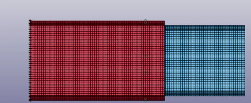
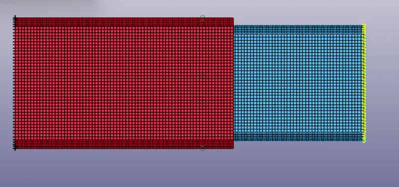
In this assignment, you will model spotwelds for the given assembly of parts and run a crash test similar to the one in assignment 4. Details about spotweld location is in the image below. The yellow line signifies the spotweld directions. You need to use 3-7 spotwelds along this line, in a symmetric manner, before running the simulation
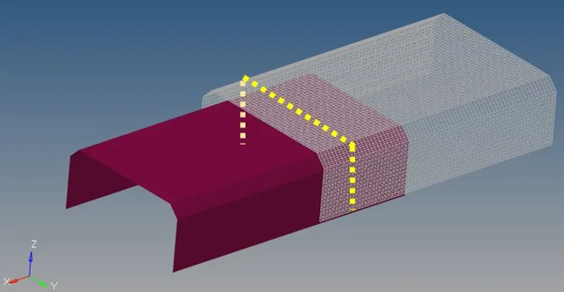
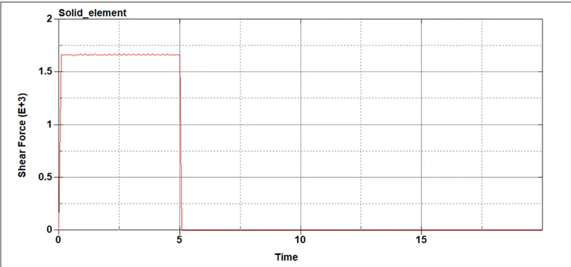
The spotwelds should be modeled using beam elements and solid elements separately. While using solid elements, one spotweld should have one solid element. The axial and shear force should be compared among beam and solid elements. The same material card using *MAT_SPOTWELD should be used for both beam and solid elements. You can use steel material data for *MAT_SPOTWELD cards and calibrate the failure data according to your results. The best simulation should have a failure at half of the termination time.
Deliverables:
All deliverable exactly similar to assignment 4 but beam and solid spotweld results should be compared in relevant cases.
- Input .k file and output files (d3plot, glstat, sleout, rcforc)
- Maximum directional stress and strain along the length of the crashbox (X strain, Y strain etc)
- Plot of all energies (total, internal, kinetic, hourglass, sliding)
Procedure:
1.create beam element.
Go to element edit-select element type BEAM-select node 1 in top shell and select node 2 In bottom node. Like that create required beams.
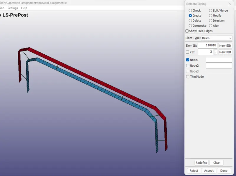
2.Assign MAT card for both sheet and spot weld.
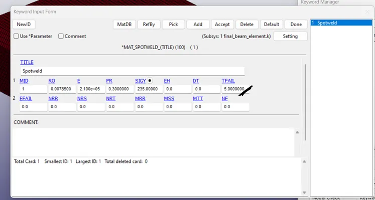
Select 100 spot weld card.
Fill all material property. And give time base fail. (Tfail)
Assign section for spot weld location.
For sheet metal location assign shell section and weld location assign BEAM section.
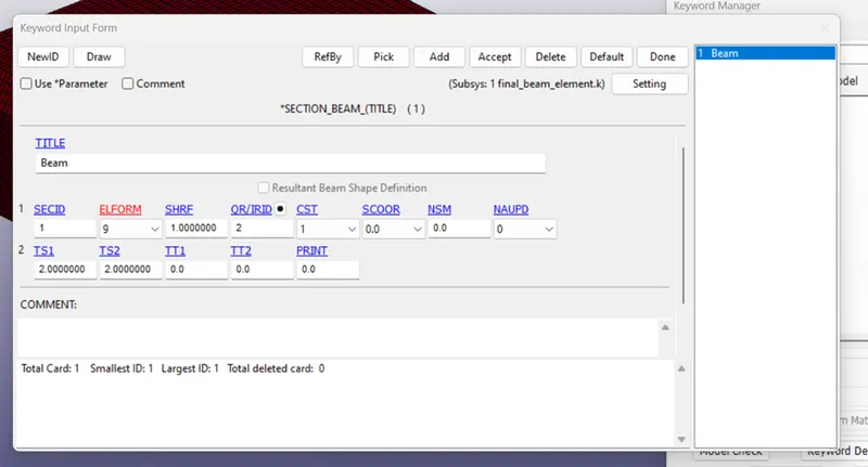
Change ELFORM based on element
Select termination and change ENDTIM
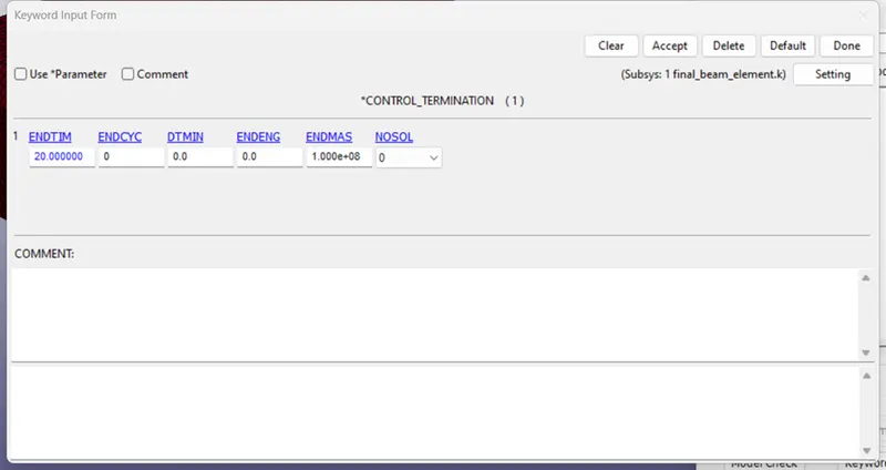
Create boundary conduction in create entity
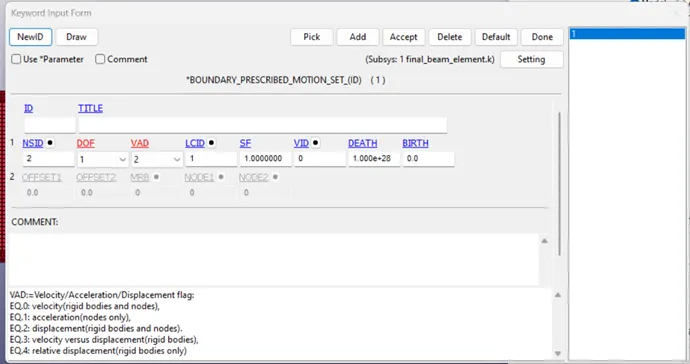
Create prescribed motion and apply DOF and VAD
Make node set for motion apply in create entity.
Make part set in create entity.
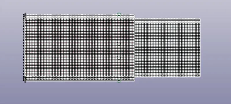
Select controls;
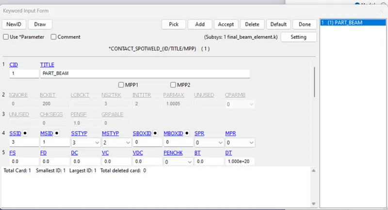
Select MSTYP for MSID and SSTYP for SSID
Select master for shell and make slave for beam element.
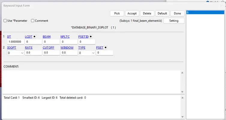
Finally create DATA Base Card.
Assign ASCII and binary D3PLOT.
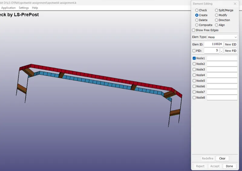
- create solid element.
Go to element edit-select element type Hexa-select node 1 to node 4 in top shell and select node 5 to node 8 In bottom node. Like that create required beams.
Then element selection use solid element.
same beam element procedure follows for solid element.
Result:-
Glsta;-
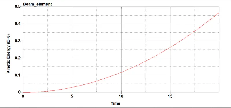
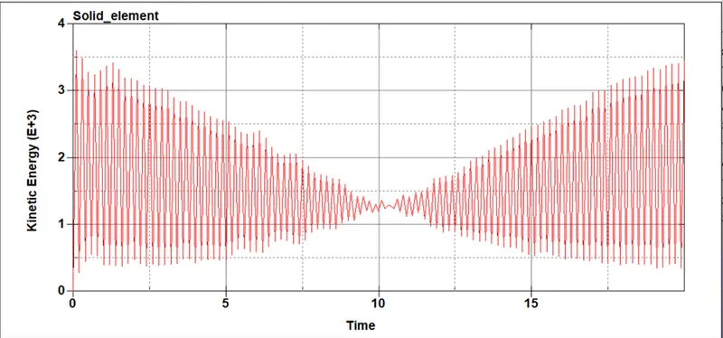
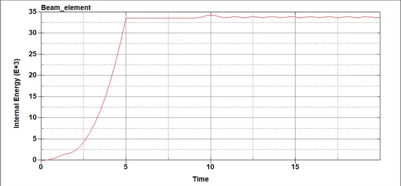
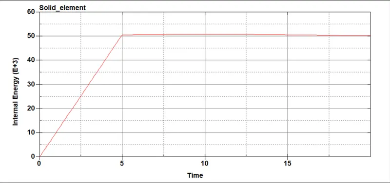
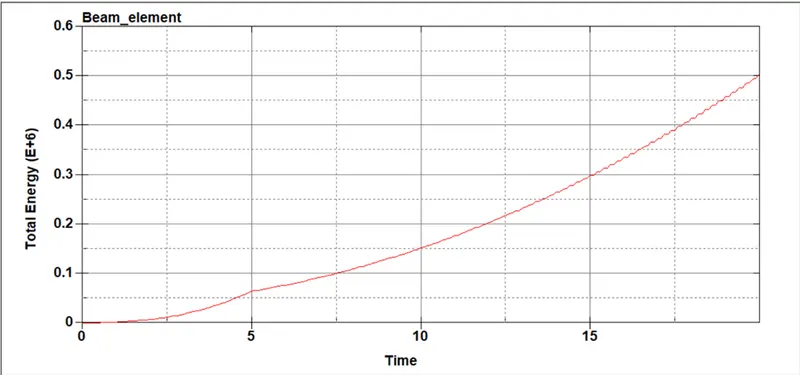
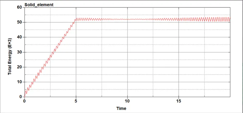
.SWFORCE;-
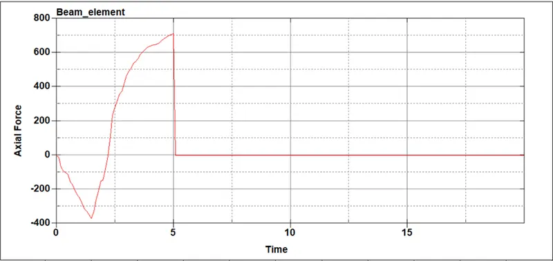
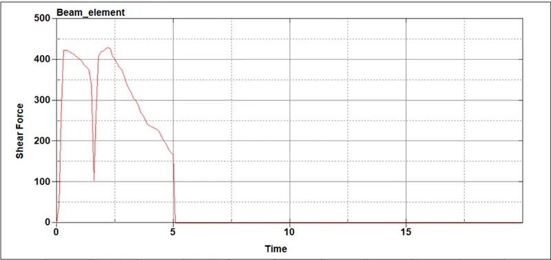
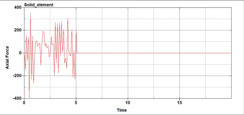
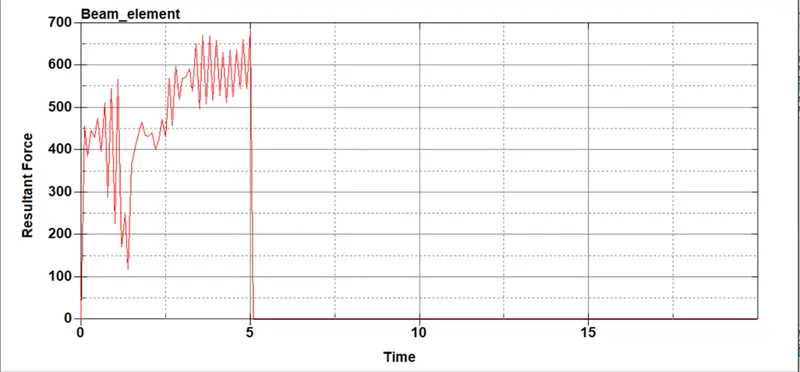
Hear beam element with stand more axial force compare to solid element.
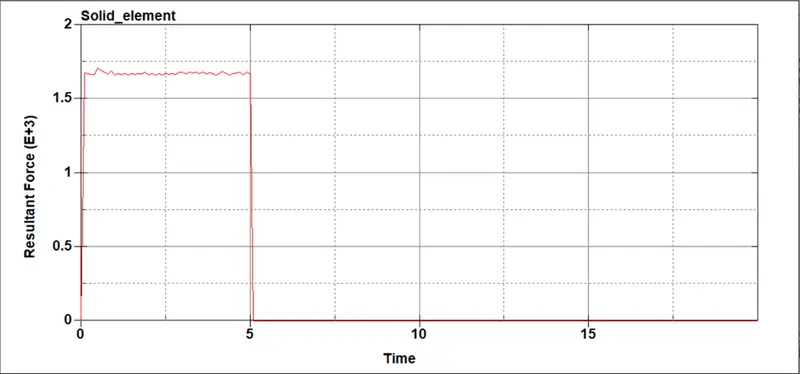
Remaining shear force and resultant are high strength in solid element.