Week - 5 - Modelling Spotwelds
OBJECTIVE :
Modeling spot welds for the given assembly of parts, using 3-7 spot welds along this line, in a symmetric manner, before running the simulation.
The spot welds should be modeled using beam elements and solid elements separately. While using solid elements, one spotweld should have one solid element. The axial and shear force should be compared among beam and solid elements. The same material card using *MAT_SPOTWELD should be used for both beam and solid elements. You can use steel material data for *MAT_SPOTWELD cards and calibrate the failure data according to your results. The best simulation should have a failure at half of the termination time.
SpotWeld Failure Criteria:
The spot weld fails, when the equation, (∣𝑓𝑛∣ 𝑆𝑛)𝑛 + (∣𝑓𝑠∣ 𝑆𝑠)𝑚 ≥ 1,
𝑓𝑛, normal interface forces
𝑓𝑠, shear interface forces.
Component 𝑓𝑛 is nonzero for tensile values only. When SN and SM are specified by curve IDs. The spot weld fails , when the equation: ( ∣𝑓𝑛∣ 𝑆𝑛(𝑇))𝑛 + ( ∣𝑓𝑠∣ 𝑆𝑠(𝑇))𝑚 ≥ 1,
where 𝑇 is the nodal temperature.
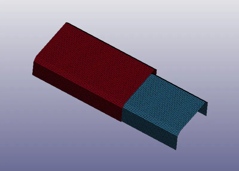
CREATING RIGID FLOOR:
Create Entity -> Rigidwall -> Create -> Planar -> Normal to Z -> Select an element in the srface for which plane has to be created.
Select -> Create -> Planar -> Select a Node to which the plane should be Normal -> Translate ->Done 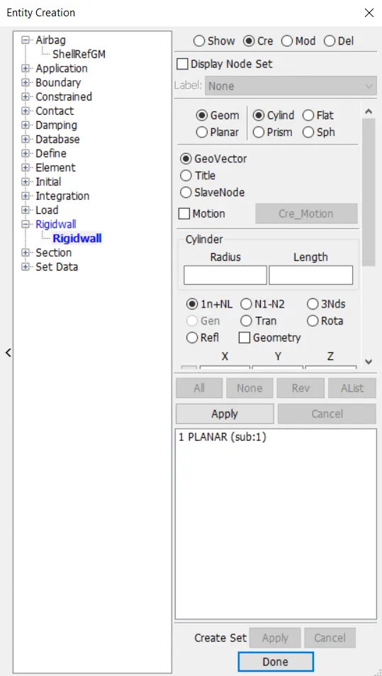
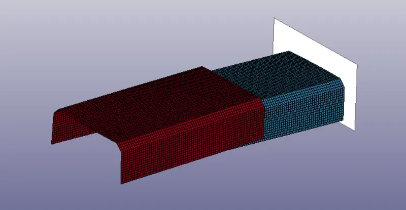
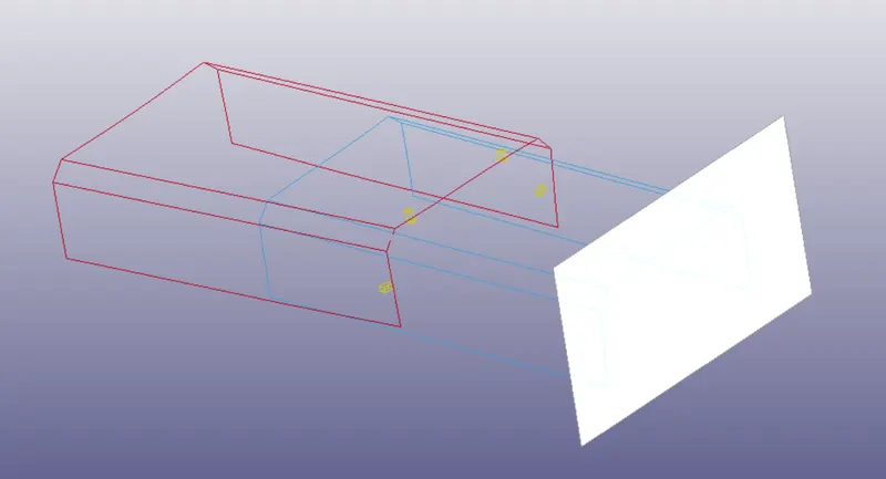
The Rigid floor is here created as shown.
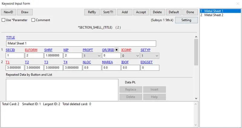
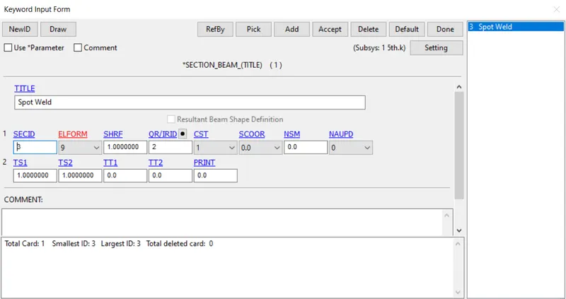
CREATING SECTION :
SECTION -> Select Solid (As Mobile is a solid defined part)
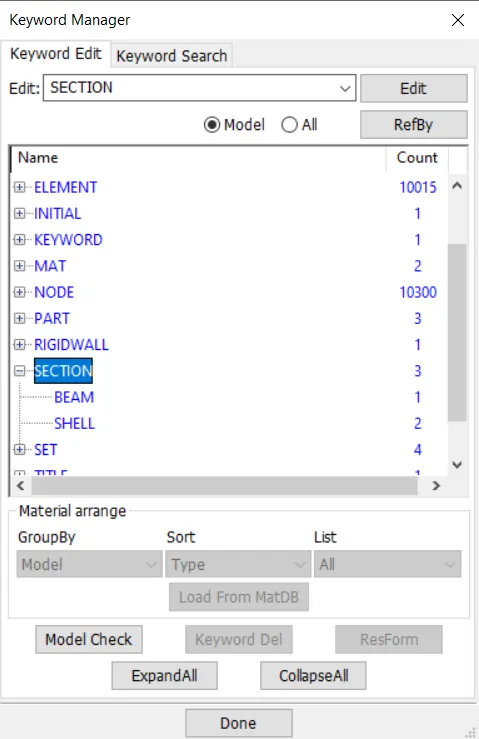
Input Section ID and Title, which should be unique.
APPLYING MATERIAL PROPERTIES :
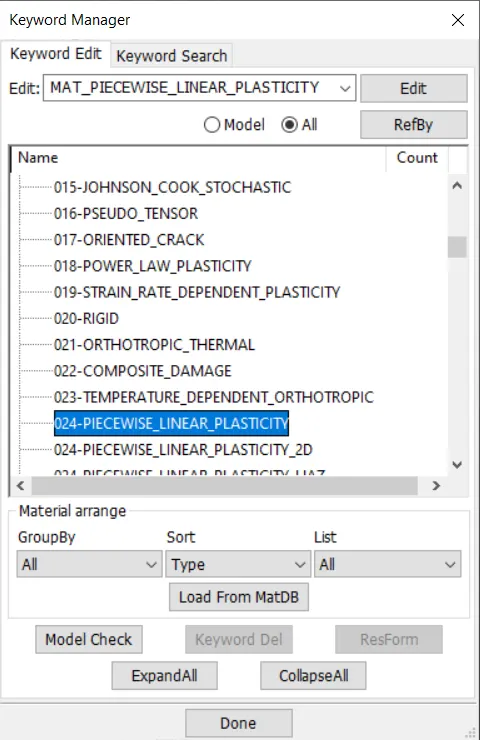
Select 24- Piecewise Linear Plasticity
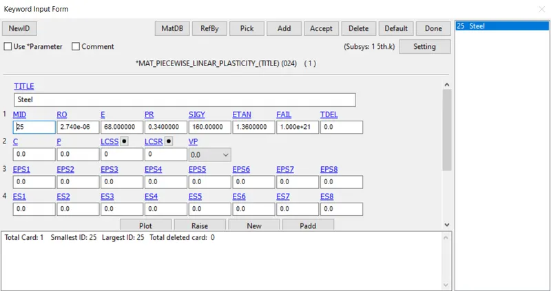
Material Properties for Aluminium Frame with unit consistency of mm | mg | gm
ETAN is given approx of (2-10% Youngs modulus)
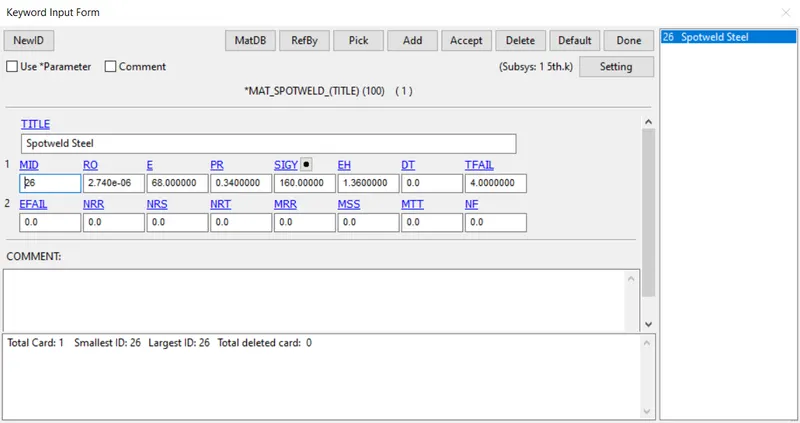
TO CREATE SPOT WELD USING BEAM
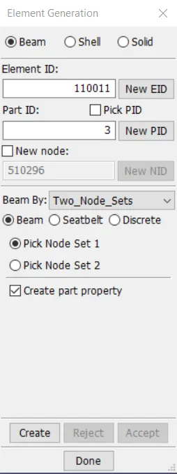
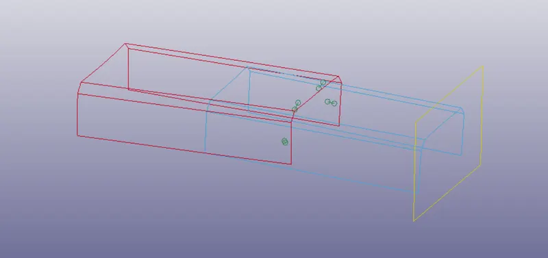
Mesh > Element Generation > Beam > Beam By > Two Node sets > Pick 2 Nodes
APPLYING VELOCITY :
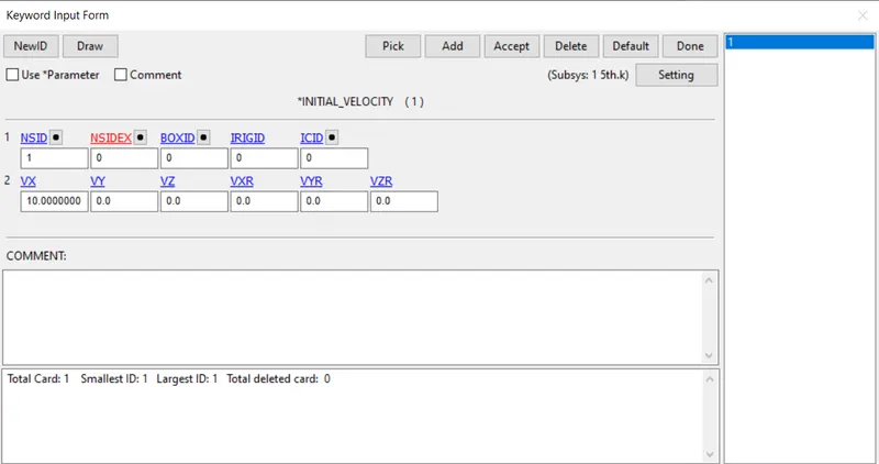
Initial -> Velocity
potential drop due to gravity, v=√2gh
here, we consider it as forced drop, in which the velocity is taken as 10mm/(ms^2)
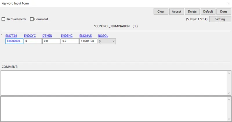
SIMULATION TERMINATION:
Control -> Termination Time
End Time is given as 8.00
DATABASE SPECIFICATION:
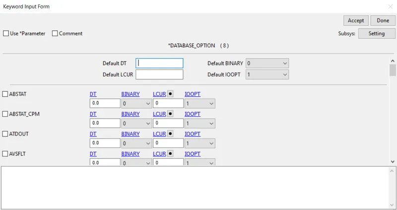
ASCII_Option:
In this Time output between intervals is specified as 0.08
for the following output Requests,
D3PLOT
ELOUT - Element Output Data
GLSTAT - Global Statics
RWFORC - Rigid Wall Forces
SECFORC - Cross Sectional Forces Data
SLEOUT - Sliding Interface Energies
SPCFORC- SPC Reaction forces
SPHOUT - SPH Output data
SWFORC - Spotweld Nodal Constraint Reaction Forces
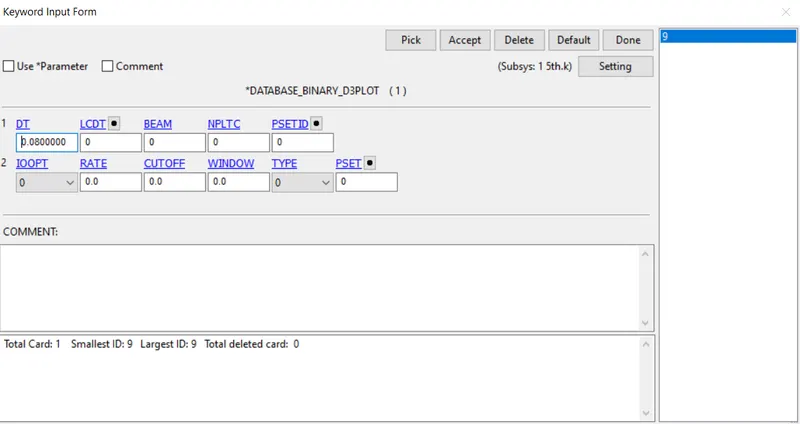
BINARY OUTPUT:
In this Time output between intervals is specified as 0.08
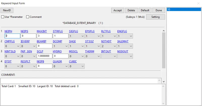
Extend Binary for assigning strain str flg 1
 .
.
INITIATING SIMULATION:
-> Open LS-RUN
-> Input file -> Select the keyword file of the Drop test
-> Run the Simulation
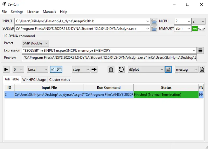
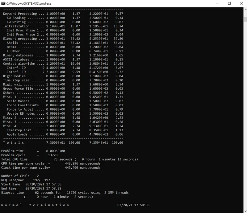
REPORT SUMMARY OF SIMULATION WINDOW:
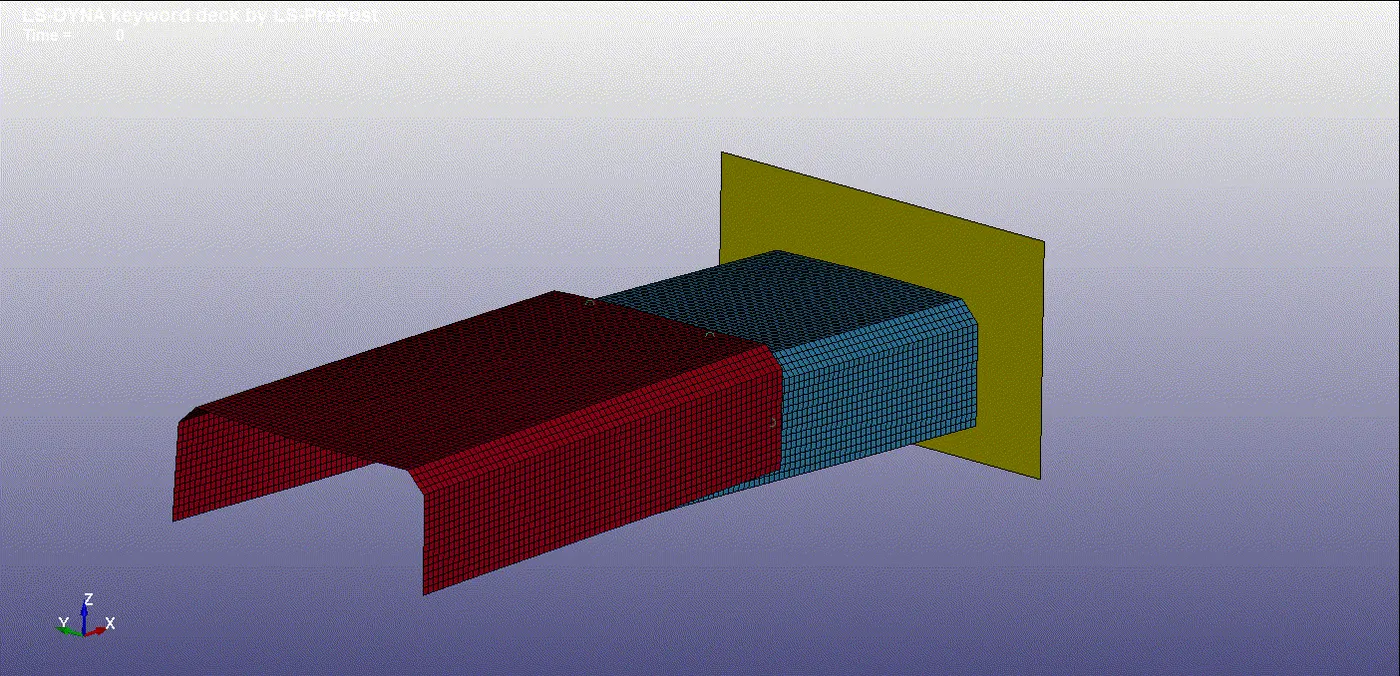
SIMULATED DROP TEST : (LS-RUN)
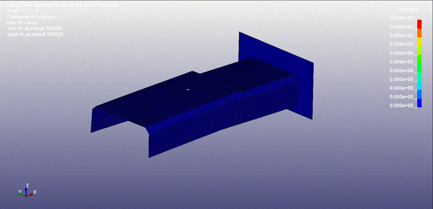
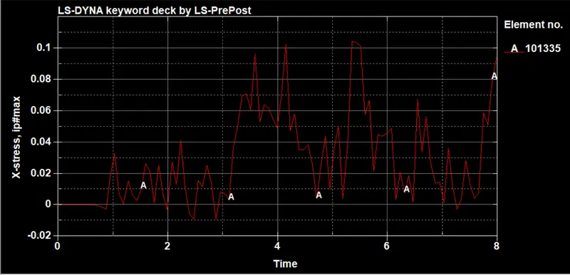
STRESS :
STRESS:
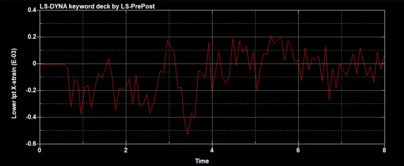
STRAIN :
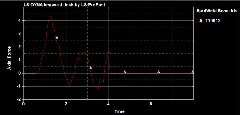
AXIAL FORCE :
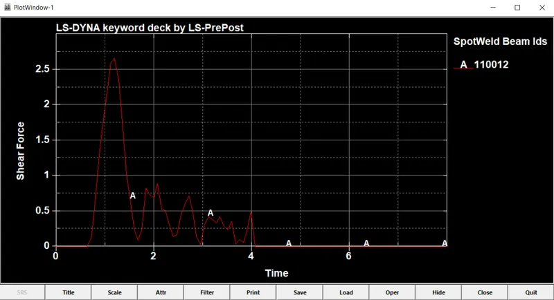
SHEAR FORCE:
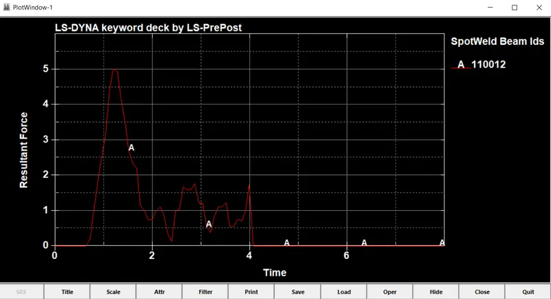
RESULTANT FORCE:
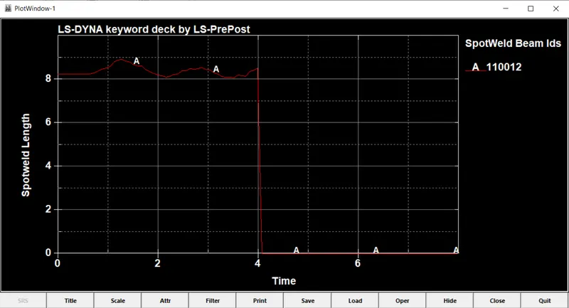
SPOTWELD LENGTH:
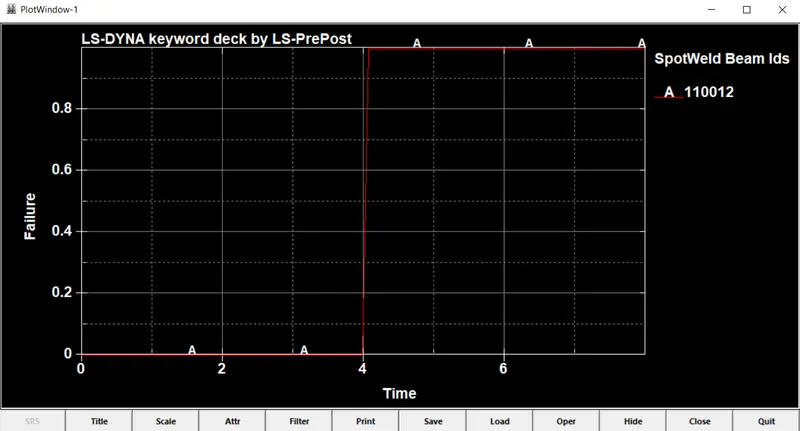
FAILURE:
RESULTANT FORCE:
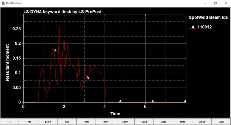
Torsion:
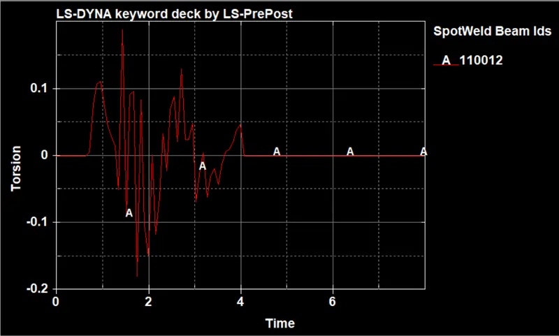
CONCLUSION :
The Simulation for spotweld using beam element is done and the results rae depicted in the graph plots.
============================================================================
SOLID :
CREATING RIGID FLOOR:
Create Entity -> Rigidwall -> Create -> Planar -> Normal to Z -> Select an element in the srface for which plane has to be created.
Select -> Create -> Planar -> Select a Node to which the plane should be Normal -> Translate ->Done
The Rigid floor is here created as shown.
CREATING SECTION :
SECTION -> Select Solid (As Mobile is an solid defined part)
Input Section ID and Title, which should be unique.
APPLYING MATERIAL PROPERTIES :
Select 24- Piecewise Linear Plasticity
Material Properties for Aluminium Frame with unit consistency of mm | mg | gm
ETAN is given approx of (2-10% Youngs modulus)
TO MAKE SPOT WELD USING SOLID:
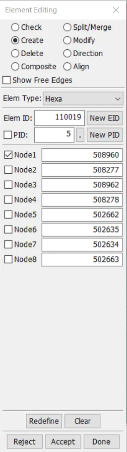
Element Tools > Element Edit > Create > Element Type > Hexa > Select Nodes
APPLYING VELOCITY :
Initial -> Velocity
potential drop due to gravity, v=√2gh
here, we consider it as forced drop, in which the velocity is taken as 10mm/(ms^2)
SIMULATION TERMINATION:
Control -> Termination Time
End Time is given as 8.00
DATABASE SPECIFICATION:
ASCII_Option:
In this Time output between intervals is specified as 0.08
for the following output Requests,
D3PLOT
ELOUT - Element Output Data
GLSTAT - Global Statics
RWFORC - Rigid Wall Forces
SECFORC - Cross Sectional Forces Data
SLEOUT - Sliding Interface Energies
SPCFORC- SPC Reaction forces
SPHOUT - SPH Output data
SWFORC - Spotweld Nodal Constraint Reaction Forces
BINARY OUTPUT:
In this Time output between intervals is specified as 0.08
Extend Binary for assigning strain str flg 1
.
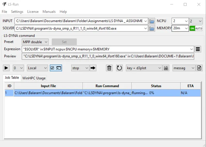
INITIATING SIMULATION:
-> Open LS-RUN
-> Input file -> Select the keyword file of the Drop test
-> Run the Simulation
REPORT SUMMARY OF SIMULATION WINDOW:
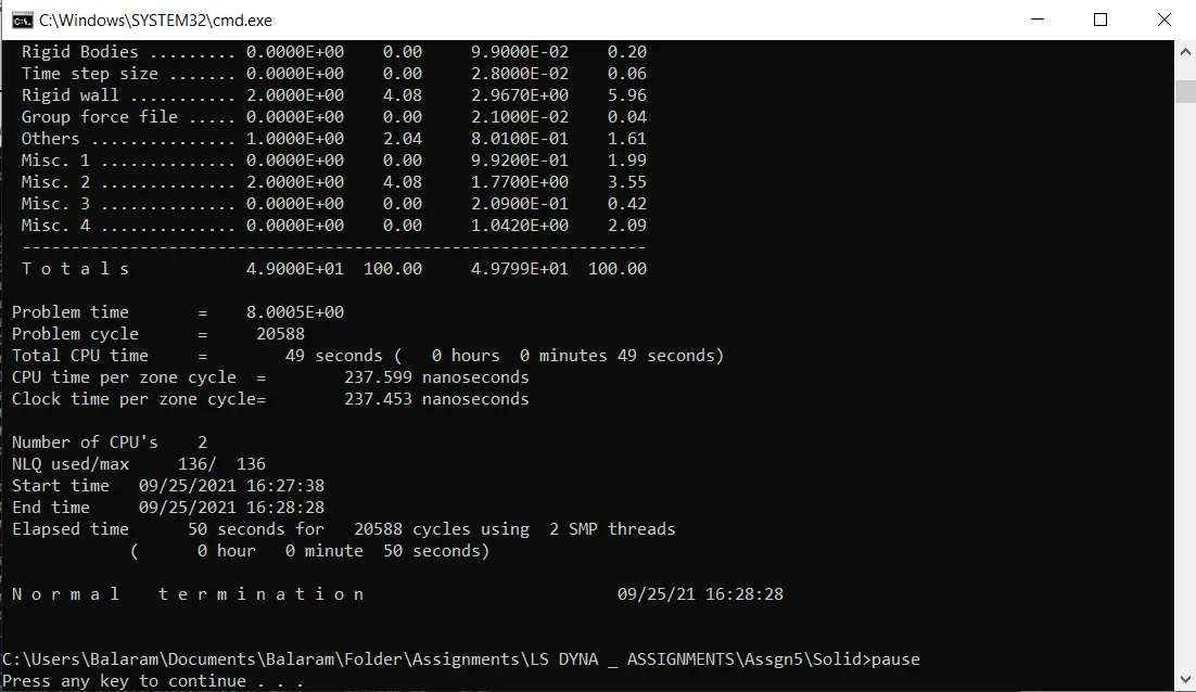
SIMULATED DROP TEST : (LS-RUN)
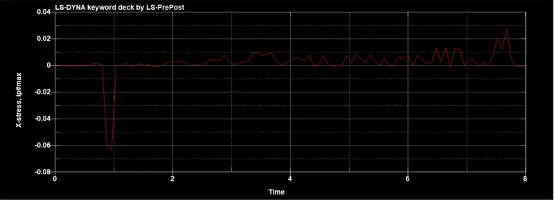
STRESS :
STRESS :
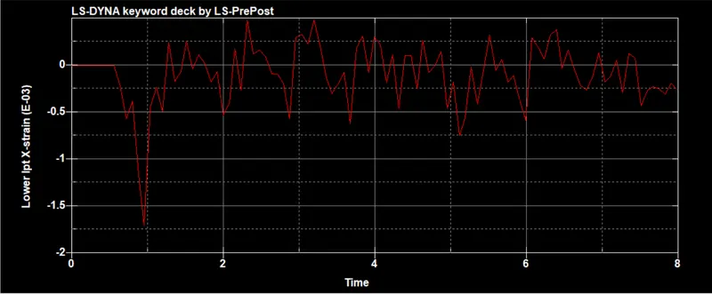
STRAIN :
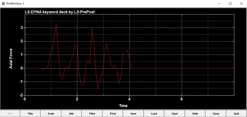
AXIAL FORCE :
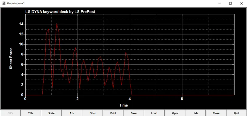
SHEAR FORCE :
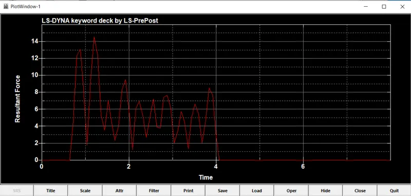
RESULTANT FORCE :
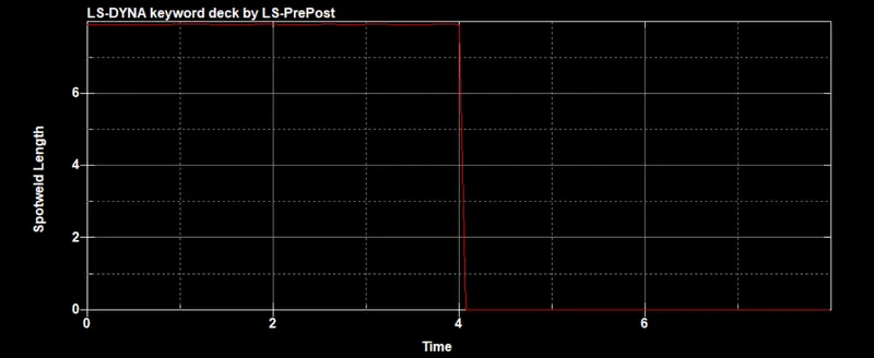
SPOTWELD LENGTH:
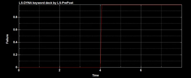
FAILURE:
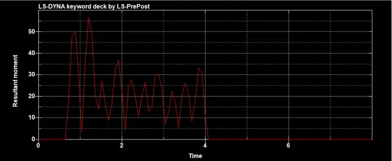
RESULTANT MOMENT:
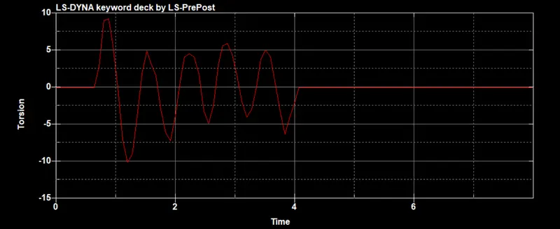
TORSION:
CONCLUSION :
The Simulation for spotweld using Solid hexa element is done and the results rae depicted in the graph plots.
=============================================================================