Week 5 Challenge- Calculating Transformation Matrix and Fixed end Force/Moments
1) Calculate the transformation matrix for a frame shown below Develop a matrix that will transform forces from their local axis x’-y’-z’ to x-y-z axis as shown in the figure below.
Ans :-
`q1' = q1cos(thetax) -q2cos(thetay)`
`q2'=q1cos(thetay)+q2cos(thetax)`
`lamdax=cos(thetax)=(x(i)-x(j))/L`
`lamday=cos(thetay)=(y(i)-y(j))/L`
`[T] =[q1' q2' a3']=[lamdax lamday 0; -lamday lamdax 0;0 0 1].[q1 q2 q3]`
2) Develop a transformation matrix for the portal frame shown below. Using the transformation matrix assemble global stiffness matrix for the structure given below
Ans :-
Programme is as below.
function [k_element]= Frame_Stiffness_Matrix(node_xy,A,I,length_element)
E = 2*10^11;
frame_stiffness=zeros(6,6);
k11 = A*E/length_element;
k22 = 12*E*I/(length_element)^3;
k23 = 6*E*I/(length_element)^2;
k33 = 4*E*I/length_element;
k36 = 2*E*I/length_element;

frame_stiffness(:,:) = [k11 0 0 -k11 0 0;0 k22 k23 0 -k22 k23;0 k23 k33 0 -k23 k36;-k11 0 0 k11 0 0;0 -k22 -k23 0 k22 -k23;0 k23 k36 0 -k36 -k33]

lamda_x=(node_xy(2,1)-node_xy(1,1))/length_element;
lamda_y=(node_xy(2,2)-node_xy(1,2))/length_element;
T_rot=[lamda_x -lamda_y 0;lamda_y lamda_x 0;0 0 1];
T=[T_rot zeros(3);zeros(3) T_rot]
k_element=T'*frame_stiffness*T
end
Explanations of the codes -
function - to create function with given inputs.
zeros - to create zero matrix.
frame_stiffness - to calculate stiffness matrix.
T - transformation matrix calculation.
end - to end the function.
Results :-
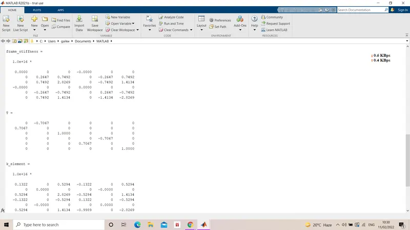
3) Using a direct stiffness method calculate displacements at A, B . Determine the global stiffness matrix fixed end forces and moments and calculate the displacements at A and B
Ans :-
Fixed end moments -
for udl loads
`(-WL^3)/12=6.25(kn)/m`
`(WL^3)/12=-6.25(kn)/m`
for point loads
`(-Pab^2)/l2=20(kn)/m`
`(Pab^2)/l2=-20(kn)/m`
After calculating fixed end forces, we calculate the v1,theta1 and v3
v1 `theta1` v3 v2 `theta2`
v1 0.096 -0.24 -0.096 0 0
`theta1` -0.24 0.8 0.24 0 0
v3 -0.096 0.24 0.096,0.02 -0.02 -0.09
v2 0 0 -0.02 0.02 0.09
`theta2` 0 0 -0.09 -0.09 0.5
after calculating theta1 and theta2, we get displacement at A and B is `-1.95*10^-4` and `10*10^-4`.
4) Calculate fixed end forces and moments for loading
Ans :-
a) fixed end forces = `P/2`
moment = `-(PL)/8` and `(PL)/8`
b) fixed end fores = `P/2`
moment = `-(Pab^2)/L^2` and `(Pa^2b)/L^2`
c)
fixed end forces = `(WL)/2`
moment = `-(WL^2)/12` and `(WL^2)/12`
d) moment = `-(PL)/8` and `(PL)/8`
e) fixed end forces = `0.5*l*p`
moment = `-(WL^2)/30` and `(WL^2)/30`
5) Develop a matlab module to compute fixed end forces and moments when load is applied between nodal points. Compute displacements and forces for the following beam
Ans :-
Programme is as below -
function [Global_Stiffness_Matrix]=Computeglobalstiffnessmatrix()

[node_coord,element_no,element_node,length_element,element_geometry,element_dof]=Getelementinfo();

boundary_conditions=Getboundaryconditions();

node_loads=Getnodalloads();
no_elements=size(element_no,1);
no_nodes=size(node_coord,1);

Global_Stiffness_Matrix=zeros(3*no_nodes,3*no_nodes);
displacement_matrix=zeros(3*no_nodes,1);
force_matrix=zeros(3*no_nodes,1);

%boundary condition
all_dof=1:3*no_nodes;
dof_specified=[];
for i=1:no_nodes
    n_dof=3*(boundary_conditions(i,1)-1)+boundary_conditions(i,2)
    dof_specified=[dof_specified n_dof];
    displacement_matrix(n_dof)=boundary_conditions(i,3);
end
free_dof=all_dof;
free_dof(dof_specified)=[];

%compute nodal loads
for j=1:size(node_loads,1)
    force_matrix(3*(node_loads(j,1)-1)+node_loads(j,2))=node_loads(j,3);
end

%gloabal stiffness matrix
for k=1:no_elements
    ele_nodes=elements_node(k,:);
    node_xy=node_coord(ele_nodes,:);
    A=element_geometry(k,1)*element_geometry(k,2);
    I=element_geometry(k,1)*element_geometry(k,2).^3/12;
    length=length_element(k);
    k_element=Frame_Stiffness_Matrix(node_xy,A,I,length_element);
    eldofs=element_dof(k,:);
    Global_Stiffness_Matrix(eldofs,eldofs)=Global_Stiffness_Matrix(eldofs,eldofs)+k_element;
end

displacement_matrix(free_dof)=Global_Stiffness_Matrix(free_dof,free_dof)\(force_matrix(free_dof)-Global_Stiffness_Matrix(free_dof,dof_specified)*displacement_matrix(dof_specified));
force_matrix(dof_specified)=Global_Stiffness_Matrix(dof_specified,:)*displacement_matrix;
disp('Displacement Vector');
disp(displacement_matrix);
disp('Force Vector');
disp(force_matrix);
end
Explanations of codes -
function - to create function with given inputs.
Getelementinfo - to take element data from the function.
Getboundaryconditions - to take boundary conditions from the fucntion.
Gernodalloads - to take nodal loads from the given function.
size - to identify number of elements and nodes
zeros - to create zeros matirx .
for - to create loop data with respect to given input.
end - to end the loop.
disp - to display the results.
end - to end the function.
Results :-
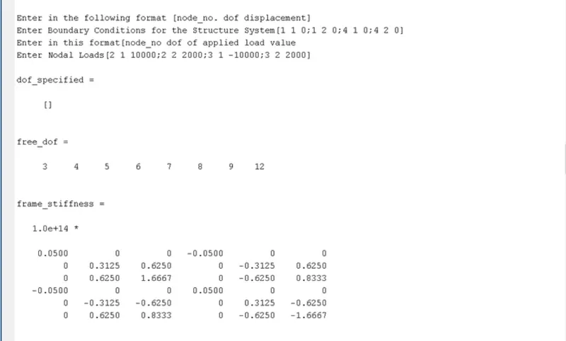
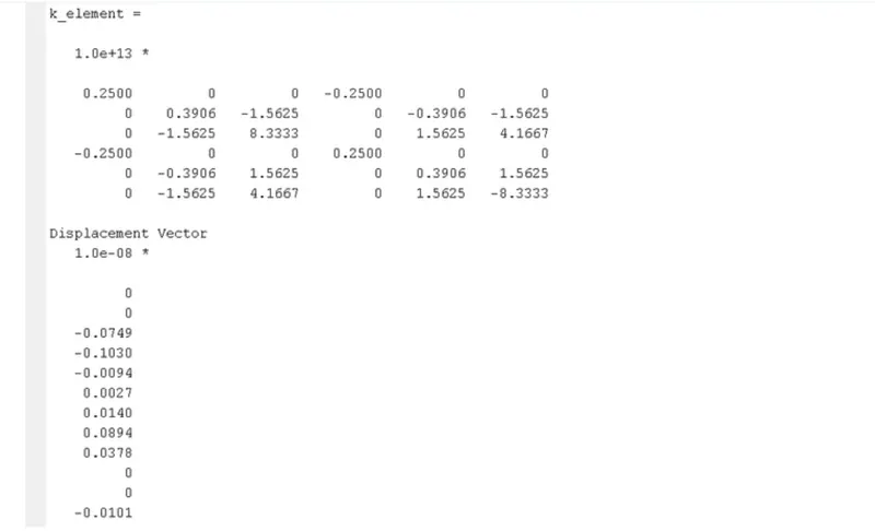
6) Calculate deflections for the beam under the loading specified
Ans :-
As,
F = force per unit length N/m
L = length m
E = modulus of elasticity N/m^2
I = moment of inertia m^4
q = force per unit length N/m
a) For point load deflection is -
`deltamax=(FL^3)/(3EI)`
b) For udl deflection is -
`delta max = (qL^4)/(8EI)`
c) For point load at center deflection is -
`delta max = (FL^3)/(48EI)`
d) For udl in simply supported beam -
`delta max = (5qL^4)/(384EI)`