Battery modeling and output behavior under UDDS load cycle using Matlab/Simulink
AIM: Generic battery simulation under UDDS load cycle
INTRODUCTION:
A generic battery model is used from the Simulink library database and configured using Samsung Datasheet for Li-ion type cell ( Samsung INR18650-25R).
The battery cell used for the following simulation is as follows:
Battery type: INR18650-25R
Cell type: Li-ion cell
Datasheet: Samsung INR18650-25R
Standard load cycles:
Standard load cycles for batteries are the values obtained by realtime experimental values using a vehicle and measuring its load requirement while driving it through an actual urban road, rural road, or expressways as per desired.
These load cycles can be used for simulating the battery performance or for battery stability when it will be actually used in a vehicle. These standard load cycles are available for free/paid on government or private company websites.
One of the examples of such a driving cycle is the EPA Urban Dynamometer Driving Schedule (UDDS)
UDDS load cycle was used to observe the realtime cell characteristics under this load cycle.
UDDS Cycle:
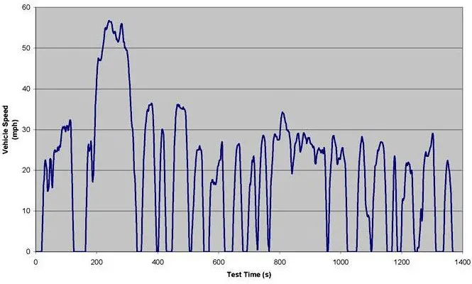
The above-obtained plot is for Vehicle speed vs time and is converted to Current vs Time as shown below.
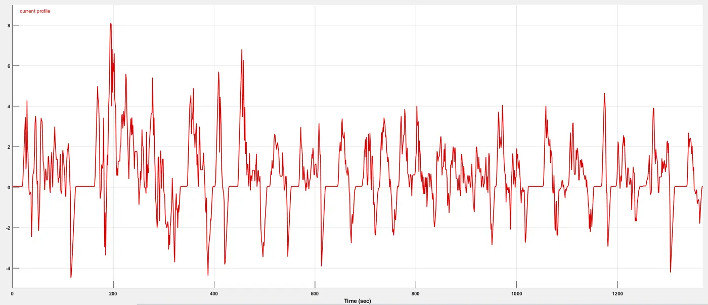
The above plots were obtained using the following conditions:
Duration: 1369 seconds
Distance: 7.45 miles
Average speed: 19.59 mph
SETUP:
Matlab-Simulink is used for the configuration of Generic Li-ion battery and set up the required simulation as shown below
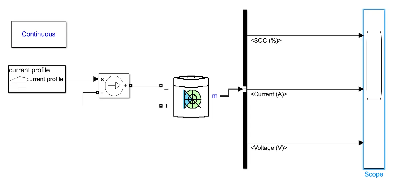
The output parameters are SOC, Current, and Voltage.
The configurations for Generic battery are as follows:
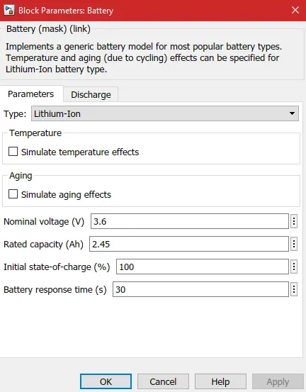
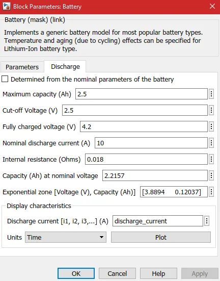
The battery is set up to Discharge at 10A (8C) nominal current. It can be observed from the datasheet that the relative capacity is 100% at 10A discharge current.
The simulation was run for 1370 seconds and the output parameters were observed.
RESULTS:
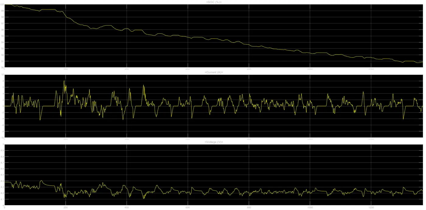
The above plot has Time (Seconds) on X-axis and Three different output parameters on Y-axis. From top to bottom Y-axis contains SOC, Current, and Voltage.
It can be observed that after one complete UDDS load cycle the battery is discharged from a 100% charge state to around 94.3% charge state. Battery output current being 10A which is more than the maximum required output current throughout the load cycle and hence load capacity is completely met throughout the load cycle.
Also, it can be observed that the output current response of the battery is quicker than the output voltage response.
Output current range: -4.2 to 8.1 A (Negative Current indicates the battery is charged at that moment)
Output Voltrage range: 4.1 to 4.41 V