Tetra meshing of plastic component (rear-view mirror) in ANSA
Objective:
The objective of this project is to perform geometrical cleanup and generate 3D tetra mesh for the 'rearview mirror' component of a car. And the mesh should follow the following quality criteria,
| S.No. | Quality Criteria | Value |
| 1 | Target/Average length | 1 |
| 2 | Minimum length | 0.5 |
| 3 | Maximum length | 2 |
| 4 | Tetcolapse | 0.2 |
This report details the process and things to consider while tetra meshing such components using ANSA.
Introduction:
The Rearview mirror is an assembly of plastic components with varying thicknesses across the component. And in cases of such components with varying thickness or thickness more than 5mm, it is recommended to mesh the model using 3D elements such as tetra, hex, penta, etc. Though brick/hex meshing would give more accurate results, it is usually a much harder and time taking process to model each and every component using hex elements. While tetra meshing is comparatively an easy and fast process. And, also tetra mesh gives fairly accurate results to prefer this method over hex meshing. Thus, hex meshing is only done for very critical components like vehicle frame mounting bushings. Thus, it is the job of the CAE engineer to weigh in the benefits and drawbacks of each before deciding the type of mesh to be generated.
The Rearview mirror is not a critical component under high stress, therefore, performing tetra meshing is good enough for it.
Procedure:
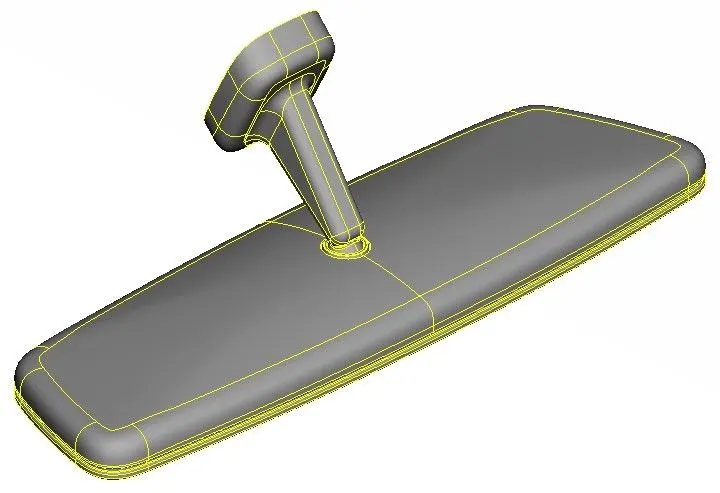
First, the rearview model is imported into the ANSA workspace. The rearview model that needs to be modeled is shown in the image below,
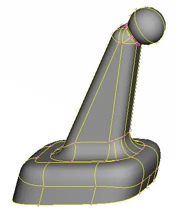
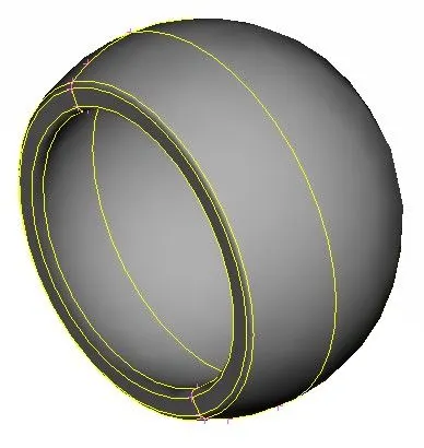
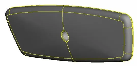
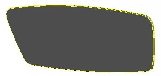
This model consists of four individual components shown in the image below,
The following is the general process to be followed for tetra meshing in ANSA:
- Properly analyze and understand the geometry
- Perform geometry cleanup
- Configure Mesh parameters and quality criteria
- Generate 2D tria mesh for all the surfaces
- Check for minimum and maximum length and repair the falling elements
- Define model as a closed volume
- Generate tetra mesh
- Check for tet collapse, dips, and kinks on surface and repair the falling elements
The first step after importing the model is to properly analyze and understand the geometry. It is important to understand the geometry and plan for meshing before starting meshing. There might be some geometrical issues like missing surfaces, duplicate/intersecting surfaces, etc. This is usually due to the format conversion process from the CAD format to the ANSA format or due to an inherent bad CAD file. All these issues need to be taken care of before meshing.
After importing the model, the Topo tool under the Faces>Topo is used to perform topology, i.e., connect all the single CONS to form a closed geometry. Next, the geometry check is performed by going to Checks>Geometry. And, no issues were found with the geometry.
Now, the next step is to prepare the model for meshing. First, mesh parameters are configured by going to Utilities>Mesh Parameters. There, target length, minimum element length, and maximum element length are configured to 1, 0.5, & 2, respectively. The element type is changed to ortho tria and all other parameters are kept default.
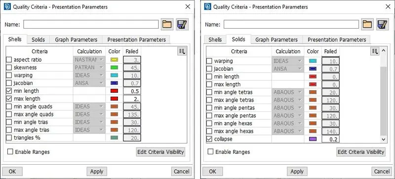
Next, quality criteria are configured by going to Utilities>Quality Criteria. And, the quality criteria file is saved for future reference. For 3D tetra mesh only tet collapse criteria is considered. The image below shows the enabled quality criteria for 2D and 3D elements.
The next step is to prepare the midsurfaces for meshing. For that, switch to the Mesh module. First, the shell element length is altered by going to Perimeters>Length and all the CONS are selected and target element length 1 is fed as length value. The same is done for all the Macros (surfaces).
Next, all the areas are checked for minimum element length and altered a little where elements might fail for minimum length. Similarly, CONS which are not essential to define a feature are removed by joining the surfaces using the Macros>Join tool. There were few fillets where elements would fail for minimum length. Such fillets were divided into middle and the top and bottom CONS are toggled, as shown in images below.
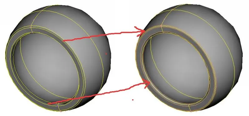
Orange CON (edge) represents the toggled CON and yellow CON is the new split done to divide the fillet into half.
Next, meshing is done for all the surfaces using Mesh generation>Best tool. Then, the created mesh is refined using the Shell Mesh>Reconstruct tool.
Ortho tria elements are used to generate mesh for curved surfaces and normal trias are used to generate mesh for plain surfaces. The reason to do so is that ortho trias give a better mesh flow for curved surfaces but results in a large number of nodes and elements compared to when done using normal trias. That's why to optimize the mesh quality and the number of nodes, curved surfaces are meshed with ortho trias and flat surfaces are meshed with normal trias. For comparison, the image below shows the mesh generated for curved surface using ortho tria and normal tria.
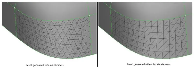
We can see that the mesh generated with ortho tria is of better quality than that generated with normal tria elements.
After generating a 2D mesh for all the surfaces, it is checked for quality criteria and no issues were found. The image below shows the part of mesh generated for the complete component.
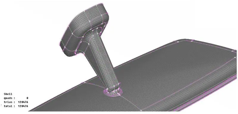
The next step is to define volumes for 3D meshing. To do that switch to the Volume mesh module and go to Volumes>Define>Auto Detect. For this tool to work the model must be already surface meshed which is already done. The tool is run for the whole database. And as expected, it detected four closed volumes and defined them automatically under properties with type PSOLID.
The next step is to generate the tetra mesh. For that, there are two tools under the Unstructured Mesh, namely Tetra Rapid, and Tetra FEM. Both can be used to generate the tetra mesh according to the quality criteria. In our case, the Tetra FEM tool is used to generate the tetra mesh. This tool generates the tetra mesh by taking surface mesh as reference and the quality criteria as parameters to be followed.
Finally, the generated tetra mesh is checked for quality criteria and no elements were found failing. If there had been any, they could be repaired using tools available under the Improve panel like reconstruct, smooth, etc. Next, the tetra mesh is checked for any dips or kinks on the surface and none were found.
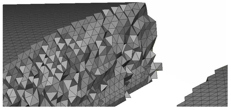
The generated tetra mesh can be visualized by hiding a few elements, as shown in the image below,
Conclusion:
The rearview mirror component was successfully tetra meshed with zero element failure. The difference between the ortho tria and tria elements was also analyzed. Finally, it is verified that there are no dips or kinks on the surface.