TERTA MODELLING FOR A REAR VIEW MIRROR OF PASSENGER CAR - using ANSA
AIM :
To check for the geometrical errors and mesh with the given element Quality criteria. And to use tetra elements to model the component and there should not any kinks and dips on the surface of the component.
GIVEN DATA :
The given data are the inputs to work. Here the given data are,
- CAD model.
- Quality criteria.
- CAD MODEL: Here the given cad model is Rear view mirror.
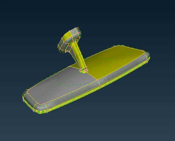
Figure 1. CAD model - Given data.
- QUALITY CRITERIA : Every product which is been produced will go through the set of quality check. If the quality check fails other steps like boundry condition & apllying loads will not be feasible, So for this reason the element quality check is performed. To identify the quality failure the quality criteria will be entered as an input data. The given quality criteria are shown in the below table. The elements should be maintained within the below given value. If the given quality value is not maintained there will be a failing in qulaity.
| S.N0 | QUALITY CRITERIA | VALUE |
| 1. | Target / Avg. length | 1 |
| 2. | Min. length | 0.5 |
| 3. | Max. length | 2 |
| 4. | Tetcollapse | 0.2 |
Table 1 : Quality criteria.
THEORY:
MESHING :
- Meshing - Automated net generated.
- A mesh is a network that is formed of cells & points. It can have almost any shape in any size & is used to solve partial differential equations. Each cell of the mesh represents an individual solution of the equation which, when combined for the whole network, result in a solution for entire mesh.
- FEM allowed for mixed types of mesh cells & unstructured meshes became feasible.
- 2D - Structural mesh.
- 3D - Unstructured as well as structured mesh.
Process of Meshing:
- Definite element size.
- Choose types of element.
- Shell mesh (2D - tria & quad)
- Various methods.
- Surface less meshing.
- Solid mesh (3D - tetrahedron, hexahedron, pyramid, wedge)
- Tetra mesh ( Unstructured mesh).
- Hexa mesh ( Structured mesh).
- Quality cruteria check.
- Remesh - Quality improvement.
ORTHO TRIA Vs TRIA ELEMENTS:
- Ortho tria capture the features more accurately than tria elements.
- Mostly, otho tria will be used in curved surfaces whereas trias will be used mostly in flat surfaces.
- Surface distortion can happen in the curved faces while we using normal trias, So to avoid those distortion we go with ortho tria elements for curved faces.
PROCEDURE:
- Import the cad geometry - Input the given cad model. Here the given cad model is rearview mirror.
Figure 2. Cad model (Imported)
- Perform Topology - In Topo module, Go to Faces ---> Topo ---> Select the model & middle click. (refer fig.
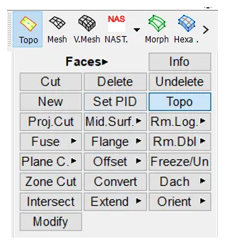
Figure 3. Topology steps
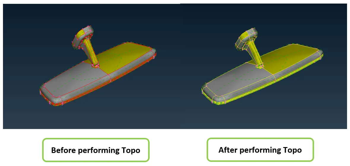
Figure 4. Before & after topology.
- Geometry cleanup - To generate FEM we clean up the geometry. Surface patch up, creating new surfaces, eleminating of triple cons in unwanted area, converting single cons to double cons in necessary area are comes under geometry cleanup phase. ANSA has some option to rebuilt the surfaces for some extent. By using checks manager we will check the geometry & if the error shows fix those error manually or by using autofix./
- Step 1: After imported the cad. Go to Checks manager > Geometry > Click Excecute to run checks manager.
- Step 2: The errors in the cad geometry will be highlighted. Now right click the highlighted errors and click fix to auto fix the errors or manually fix the error by releasing the hot points & cons. Here I have fixed the error by using autofix. Now the geometry will rerun for checks and the error will be solve.
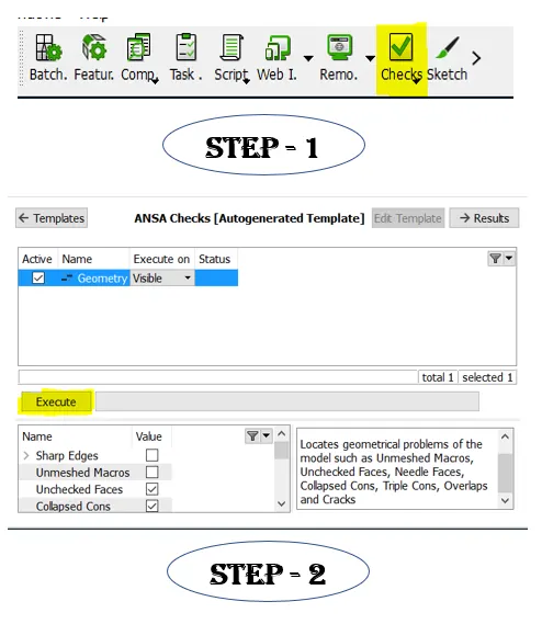
Figure 5. Steps for geometry clean up.
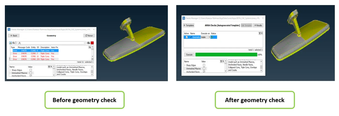
Figure 6. Before & after geometry check
- Quality criteria - Every product which is been produced will go through the set of quality check. If quality check fails other steps like B/C & applying loads will not be feasible, So element quality check will be performed. The given quality criteria values been enterd in quality manager ( shortcut key : F11). These colours are customizable and can be seen while meshing if the elements are beign failed. These failed elements should be corrected and the elements should matches the quality criteria.
- Step 1: To enter the given quality criteria values Click quality criteria / press F11 to open quality criteria window (for shortcut) --> Quality criteria window will open. In shells & solids. Enter the given quality value to the particular tab and edit the colours for the better visualization of quality failure.
- Step 2: Apply. Then save the quality criteria value and import it while reopening the file.
- Step 3: Go to presentation parameters as shown in the below figure. There under Graphics --> select Enable %.
- Step 4: And also under detail & demand effect slide the curser to all details as shown in the below figure.
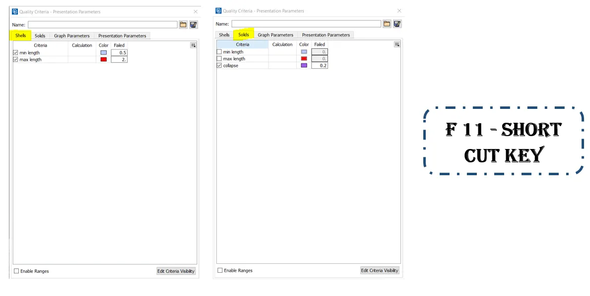
Figure 7. Quality criteria - Steps 1 & 2.
Here in tetra modelling, we have to consider only for minimum & max. length in shells criteria and to consider the tetcollapse in solids criteria
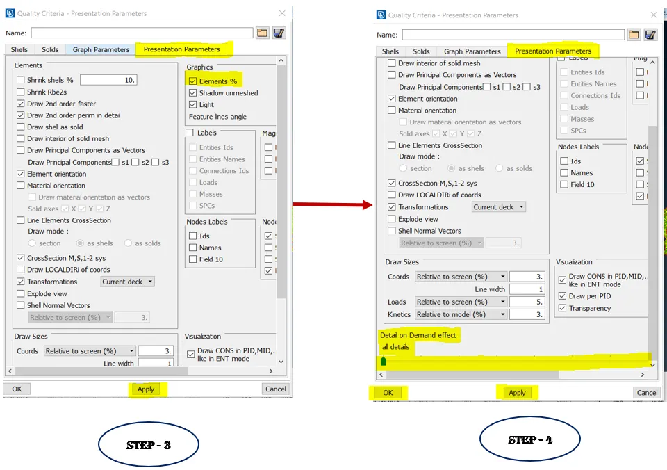
Figure 8. Quality criteria - Steps 3 & 4.
- Set mesh parameter - Mesh parameters is nothing but defining the meshing parameters. Once assiging the qulaity value mesh parameter has to be set.
- For that Go to Mesh parameter --> Enter target length, Min. target length & Max. target length. Check the parameters highlighted in yellow colour as the below given figure before giving OK.
- Since, it is a tetra modelling we should select for orthotria / tria elements.
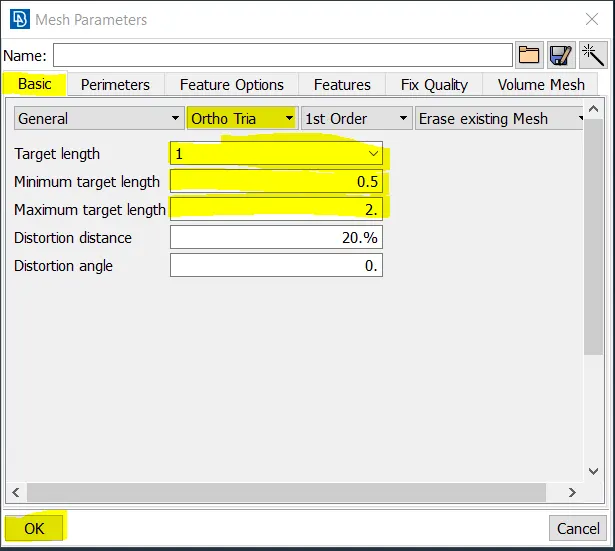
Figure 9. Mesh parameters setup
- Meshing - Automated net generated.
- Step 1: Before meshing measure the fillet regions and see whether it will fail for min. legth quality criteria. If so it fails perform defeaturing on the fillet region by using parametric cut.
- Step 2: Now, generate to mesh the model. Here I have used spot mesh as well as map mesh algorithm whenever needed.
- As we selected in mesh parameters, the meshes will be in trias & those trias have to converted into tetras by eliminating the off element tetcollapse.
- After completing the tria mesh it should be converted to tetra mesh.
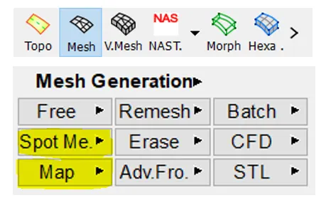
Figure 10. Mesh module - Step 1 & 2
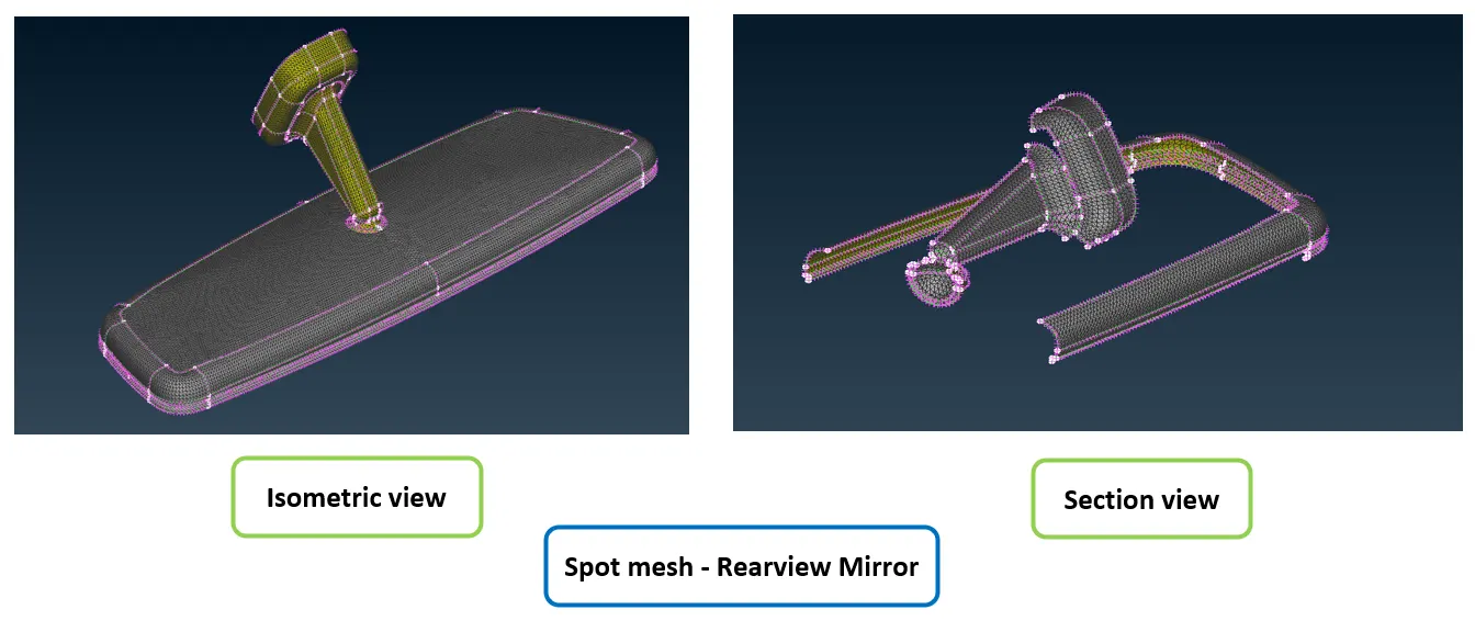
Figure 11. Spot mesh - Rearview mirror
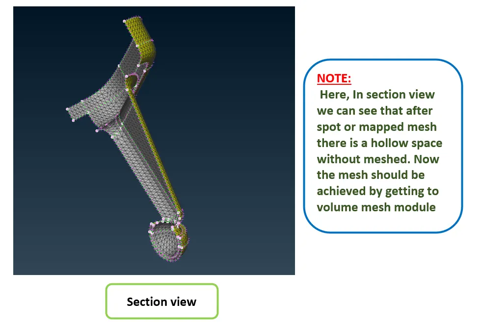
Figure 12. Spot mesh - section view
- Here, In section view we can see that after spot or mapped mesh there is a hollow space without meshed. Now the mesh should be achieved by getting to volume mesh module.
- Volume Mesh - As shown in above figure - section view, we can see that after spot or mapped mesh there is a hollow space without meshed. Now the mesh should be achieved by getting to volume mesh module.
- After completing the tria mesh it should be converted to tetra mesh.
- Tetra mesh are the unstructured mesh where ANSA uses to generate tetra elements inside any component where the surface is meshed by trias/ortho tria elements.
- Before making to the tetra identify that the geometry has a closed volume.
- Step 1: In Volume mesh module, Go to --> volumes ---> define -> click manual. Now mode tab will pop up then select Auto & select the model then ---> Do middddle click. By doing this we will be able to create a Psolid property.
- Step 2: Then, Go to --> volumes --> List. Now the volume PID will be open as shown in below figure. Also you can see the volume property as type : undefined & status : unmeshed. Now,
- These should be defined and meshed by right clicking the PID and clicking remesh.
- In remesh has to select the algorithm as tetra rapid or tetra FEM. Here I gone with Tetra FEM algorithm. (refer the below figure)
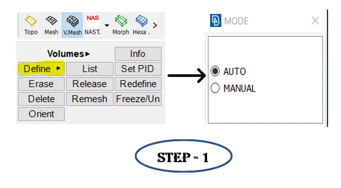
Figure 13. volume mesh - step 1
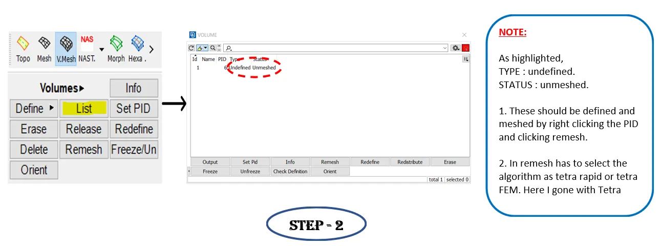
Figure 14. Volume mesh - step 2
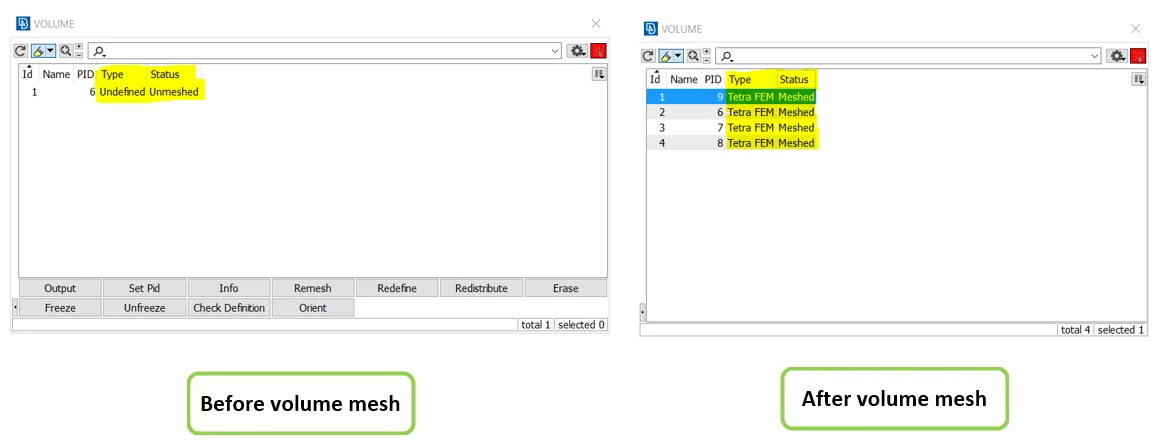
Figure 15. Before & after volume mesh (PID)
- Now the volume mesh has been completed.
- To eliminate the tetcollapse off elements. In voume mesh, Go to ---> Improve --> Fix quality. (OR) In mesh module, Go to --> Grids --> Move free.
- To view off elements move from shadow mode to hidden mode. So that we can easily identify the off elements and will be able to remove it in hidden mode.
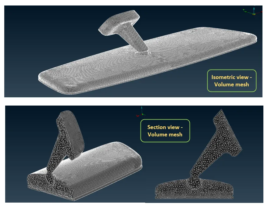
Figure 16. Volume mesh - Snap
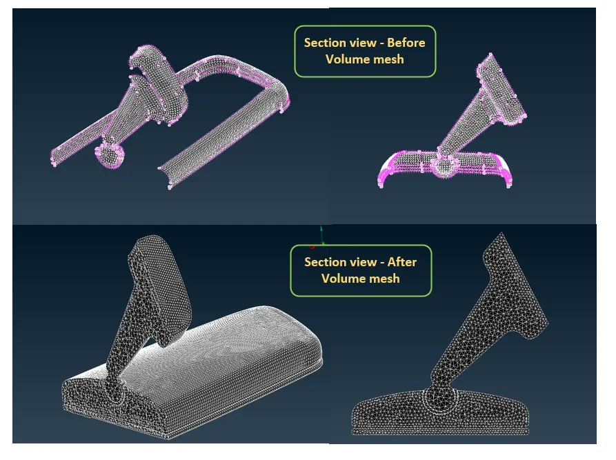
Figure 17. Snap of before & after volume mesh
DETAILS OF ELEMENTS:
- Hence there has been 100% tria and tetra elemnts in the model as shown in the below figure.
- Since, the quads are not there, the unstable pyramid elements are not found while volume meshing.
- As you see the list given in the below figure, there is been no failure in quality for Min. & max. length & tetcollapse.
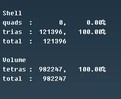
Figure 18. Details of elements
LEARNING OUTCOMES :
At the end of this challenge, I can able to
- Perform Tetra modelling for any complex automotive components.
- Identify the quality failure and resolve the failure & improve the mesh quality.
- Work on ANSA with a flow.
CONCLUSION :
As per the aim, the given component - Rearview mirror has been checked for the geometrical errors and mesh with the given element Quality criteria. Also tetra elements are used to model the component and there has not been any kinks and dips on the surface of the component.