Week - 5 - 2D meshing for Plastic components
Objective-
To extract the midsurface and mesh the given bottle cap component under the given quality criteria.
|
S.No |
Quality Criteria |
Value |
|
1 |
Target/Average length |
1 |
|
2 |
Minimum Length |
0.5 |
|
3 |
Maximum Length |
3 |
|
4 |
Aspect |
3 |
|
5 |
Warpage |
15 |
|
6 |
Skewness |
45 |
|
7 |
Jacobian |
0.7 |
|
8 |
Minimum Quad Angle |
45 |
|
9 |
Maximum Quad Angle |
135 |
|
10 |
Minimum Tria Angle |
30 |
|
11 |
Maximum Tria Angle |
120 |
|
10 |
Tria Percentage |
15 |
Procedure :
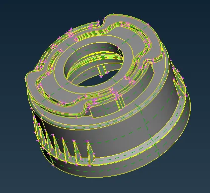
Step 1 : Importing the component
- click file > open > Bottlecap
- change the DRAW MODE to ENT.
Step 2 : Seperation process
- Click the set pid icon, and select the seperate entities
- By using the boolean operations like OR,AND,NOT present in the focus menu
- After speration, store the each component in seperate name for easier usage
Step 3 : Geomentry Cleanup
- By using the manage lock option, show the particular working component in workspace
- By using the ORIENT option, modify the faces of the component
- By using the FINE option, change the resolution of the curves and cons
- After the geomentry cleanup, go to checks > geomentry for fine cleanup, that we missed
- And click the execute, and execution process must shown as 100% and status as green mark as shown below
- If there is any errors shown, Try the FIX option by right click the error or fix it manually
Step 4 Creating Mid surface
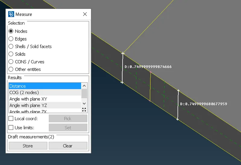
- After geomentry cleanup, Measure the thickness of the component
- For measuring thickness, use the MEASURE command in the utility option
- In the measure option, Choose selection as Nodes and select the two nodes, as shown below
- Check the tickness of component across various places to ensure the same thickness
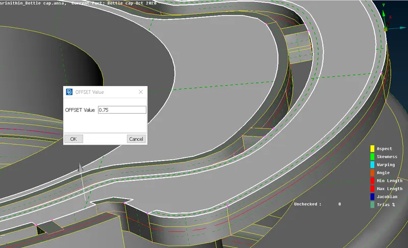
- Then select the OFFSET option in FACES command.
- Then select the face option and click either upper surface or lower surface of the component.
- Then click the FEATURE command to select the overall upper surface of the given component.
- Then click the middle mouse button and give the offset distance( THICKNESS / 2 ) and the click ok.
- Then click no for deleting the parent component.
- Now midsurface for this component is created.
Step 5 : Preparing for mesh
- Again by using the FINE command, we improve the resolution of the 3D curves
- Then change TOPO to MESH mode
- Then select the LENGHT option in the PERIMETER command
Step 6 : Assign Quality cretiria
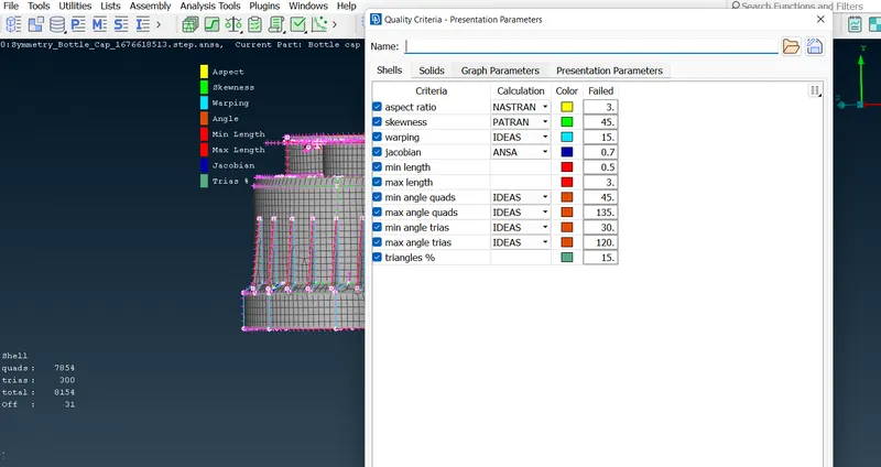
- After doing this process, we have to assign the quality cretiria for our mesh
- To do this, press F11 key from our keyboard
- Then assign the various quality cretriria as mentioned below
- Then, click the MESH PARAMETER command in the UTILITIES
- In that mention the target element size, minimum and maximum element size and the click OK
Step 7 : Meshing
- Now we have to generate the mesh for our component
- For thet Select the BEST in the MESH GENERATION option
- BEST command gives the better mesh quality by using its best algorithm
- Then change to HIDDEN mode from shadow mode for identifing element fails
-
- By using the RECONSTRUCTION and SPLIT commands give the better mesh flow for that surface
- Avoid Tria elements at fillets. Eliminate them by using Swap, Split and Join commands
- No mesh Transition on constant radius fillets/curvatures.
- It is always preferable to have two or more rows of elements at fillets so that the FE model will capture the curvature.In one fillet there should not be variation in number of rows throughout.
- To create two rows of elements, Split by Edges can be usedCircular holes aInstead of zig zag mesh pattern, a structured or smooth mesh is recommended.
- i.e. Nodes should be aligned in the same linere much important in Durability, Fatigue and NVH analysis.
- So it should be modeled carefully with at least one layer of quad elements around the periphery of a circular hole.
- Tria elements will add stiffness so it is not desired to have tria elements .
- These above steps has to be followed for aother componwnts also
step 8 : split, Join, swap and paste commands
- use the split command for dragging the trias to forward in the component
- use join command for joining the two trias into one
- use swap command for dragging the trias sideways
- use paste command for dragging the trias backward direction
- use this tools effectively for obtaing the better meshflow in the component
- And to eleiminate the opposite trias and rotating quads
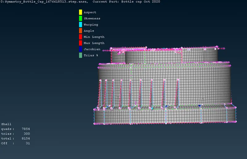
Result :
- Thus the Mid surface and meshing for the given bottlecap component under given quality cretiria is done successfully.