Week - 5 - 2D meshing for Plastic components
2D MESHING OF AN PLASTIC COMPONENT USING ANSA
AIM: - To do Preprocessing of an given BOTTLECAP Model using ANSA software.
OBJECTIVE: - To do the 2D meshing of an bottlecap Model of sheet metal within the given element quality criteria, after the geometry clean-up & mid-surfacing.
CAD Model Image: -
PROCEDURE: -
- GEOMETRY CLEAN-UP: -
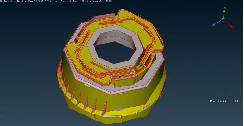
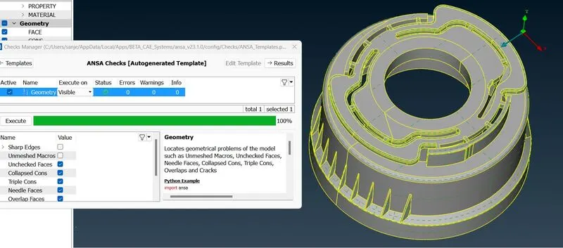
Importing the model from other software to ANSA results in some geometrical deviations which needs to be cleared before proceeding to other steps. To perform geometry Check Tools--> Checks--> Geometry. In General needle faces and Unchecked faces error occurred which is common while importing the model to ANSA from Modelling software. Images shown below were the geometrical errors showed up in Hood inner panel while performing Geometry Checkup.
To clear these errors in ANSA either we can use AUTO FIX option or Fix the errors manually one by one.
- Auto FIX option in ANSA detects the deviations and remove the errors by itself. To Auto Fix the errors Right Click on the error and click on Fix now the error will be fixed.
- To FIX the errors manually you need to find where the errors is occurring to know that Right click on the error and click Show only it will Highlight the error. To get the clear idea on the location of error we can get the neighboring faces using neighbor option or by using AND Boolean Operation.
- Needle faces and Unchecked faces can be cleared using delete option from faces module once the errors were highlighted.
- Check for geometry from check tools once again to confirm that the model is 100% clean.
Now our geometry is clean without any translation issues or geometrical deviations so we can proceed to topological activity.
- TOPOLOGICAL ACTIVITY: -
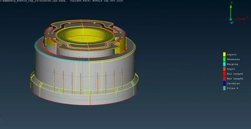
Topology describes how the different faces and features of the geometry gets connected with each other by forming CONS. There are 3 types of CONS which are SINGLE CON(Red), DOUBLE CON(yellow), TRIPLE CON(Cyan Blue). Before mid-surfacing the entire model must be of double cons, rest all the single and triple cons must be removed for getting better results while doing analysis.
Boundary Cons of the faces and Features were called as feature lines other Cons in the Model were called as Construction Lines which were generated during modelling of the component. Construction lines can be altered as we want to get the better mesh flow. Feature lines should not be disturbed as it will result in Change in geometry however if the cons Length is less than the minimum element size it will result in element failure under such circumstances the feature line can be altered up to some extent without giving up the design feature of the part.
In the model above there are two feature line close to each other(<2mm) where element will fail. In order to avoid element failure one of the feature line is deleted which will not have much impact on the entire design.
The curved feature lines can be edited and made straight lines so that the surface gets divided into small rectangles which will help us in giving proper quad meshes.
In the topological activity final step will be orienting the faces using FacesàOrient option. Orientation in ANSA indicated by Grey or Yellow surfaces Grey surface usually acts as a positive direction and Yellow acts as a negative direction. Face is said to be inconsistent if one face having both the Grey and Yellow Colours. FacesàOrient option will fix this issue by changing one side of the face to be yellow in colour and other side to be Grey colour. Now the model is consistent.
3.MIDSURFACE GENERATION: -
Mid-surface is the exact middle layer or surface of the component having uniform thickness over the part. In this component or sheet metal having the thickness of 0.75mm then the surface at the 0.375mm from any of the face considered to be a mid-surface.
In ANSA Mid-surface can be generated by two ways:
- FacesàOffset option
- FacesàMid-surface optionà Skin option
Lets discuss about these options:
- FacesàOffset:
This is manual method to generate the mid-surface. Mid-surface for the entire component is generated by generating the faces one by one by FacesàOffset command where you have to give the offset distance manually(Thickness/2). In this method we have an option to keep the original face or to delete it. Once the mid-surface is generated for the entire model they are not associated with each other. ANSA will indicate this by using a Single con on the boundaries of all the surfaces. To stitch all the faces with each other FaceàTopo option will be used. Select FaceàTopo àSelect the faces we want to Stitch-->Middle mouse click, Now the faces were attached with each other indicating the double con where the two surfaces attached together. In this method the child surface orientation may differ from the parent surface so it is advisable to perform Faces-->Orient one the Topo performed after Mid surface generation.
- FacesàMid-surface optionà Skin option:
This is auto mid generation option by which Mid-surface is generated by deleting the original faces. To generate the mid-surface Select Faces-->Mid-surface now select the faces for which you want to generate the mid surface then middle mouse click now ANSA will highlight One side of the Face Red in Colour and other face in Green Colour and the faces in thickness region in Blue colour now Middle click Now the original faces will be deleted automatically leaving the Mid-surface on the work space. It is mandatory that red and green faces shouldn’t be neighbouring surfaces
In this model Faces-->Mid-surface is used to generate the mid-surface as it saves time than FaceàOffset option as the model having higher number of faces. Possibility of errors increases in former one than the later one.
4.SET PID: -
PID is property identification number. We have to assign thickness and the material to the model. To set PID Faces-->Set PID is used. Select the faces and Middle click. Now the properties window opens up. Now Right Click on the window New-->PSHELL now as shown in fig.
Now the PSHELL dialog box opens up where you will enter the thickness. For lock area extra support the thickness is 1.2mm. Now click OK thickness is assigned to the mid-surface
A dialog box opens as shown above Enter the properties of materials like Youngs modulus, Poisson Ratio and Density values. Click Ok now material will be added to materials list. To apply that to the our PID. Right click on the material-->Apply. Now the property help dialog box opens up click on the part’s PID now ANSA will highlight the parts in which that materials property will be applied. Click Ok. Now the material and thickness property is applied to the particular model. To check whether the PID is applied to the model or not, switch to PID mode from ENT mode in Drawing styles bar. The model will change into same colour as the colour of the particular property is identified in Properties window.
5.DEFINING MESH PARAMETERS AND QUALITY CRITERI: -
Quality of the mesh is user defined one as it varies for different applications. Quality of mesh will be defined by Mesh parameters and Quality Criteria. Mesh parameters option is available in the Utilities Bar. In that window average element Size, Minimum Element Size, Maximum Element Size and order of Mesh will be defined as shown below
Mesh Quality criteria also need to be defined from the Utilities bar or by pressing F11.
Our quality criteria inputs for the mesh is given below
6.MESHING GENERATION: -
Mesh generation is process of discretizing the entire model into smaller elements.
2D mesh has two types of elements:
- Quadrilateral or Quad Elements
- Triangular or tria Elements
Quadrilateral Elements:
Quad elements were the elements having four nodes. Square is considered to be an ideal quad element and the deviations were calculated in comparison with the square element. Quad elements were structured elements. They have short processing time and also have higher accuracy. Therefore, Quad elements were preferred over the tria elements.
Triangular Elements:
Tria elements consists of three nodes. Equilateral Triangle is Ideal Tria element and deviations were compared with the Equilateral Tria Element. Tria element is said to be unstructured mesh. Stiffness of the Tria element is high which results in highier processing time and also have low accurate results. Therefore, we should try to avoid the maximum possible number of triangular elements.
Rotating Quadrilateral Elements:
Rotating quad elements were formed when any one corner of the 5 quad elements meet at a point to form a Star like structure. Even thought they were quad elements they should be avoided in the model as they act like the tria elements.
Meshing:
Step 1: Mesh Generation-->Best selected from the Mesh Module and selecting the face that needs to be meshed.
Step 2: Now Middle Clicking will generate the mesh
Mesh is generated for the entire model by following above said steps.
Steps followed to create the Proper Mesh for this model:
- In this model meshing started from middle of the model and moved away from the center. So that it is easy to eliminate the triangular elements.
- Outer hood surface is large therefore the face is discreted such that the discreted face form a rectangle so that we can avoid maximum number of triangular elements.
- Since the Outer and Inner panel of the Hood is Symmetrical. One half of these parts were meshed and Mirrored using Transform and symmetry with the help of 3 point mirror option.
7.MESH FLOW AND MESH QUALITY IMPROVEMENT: -
In ANSA mesh can be generated easily but the mesh will have lot of elements generated such that they fail to fulfill the Mesh Quality criteria an also the mesh will have the Triangular elements which needs to be eliminated. Mesh Flow and Mesh quality improvement is the most important steps in order to achieve good mesh quality and good Mesh Flow. To improve the mesh Quality there are many options available in ANSA. Let’s discuss them in detail and how they used to achieve good mesh for the model.
- Reconstruct
- Smooth
- Split, Swap, Join
- Changing Nodal numbers
- Edge2Perimeter
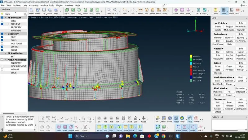
Mesh is generated and the Mesh quality and the Mesh flow is improved using the above said options for the entire model.
After meshing the draw shell to solid parameter in presentation column in quality window was checked to provide the thickness to the mid-surface.
Final Model
RESULTS: -
- Preparing geometrical error free model for preprocessing.
- Understanding the construction lines and feature lines of the model.
- To make the topological activity without disturbing the features of the model.
- Generating Mesh.
- Improving the Model’s feature and the Mesh element quality.
- Using various options to improve the Mesh quality and Mesh flow