Week - 5 - 2D meshing for Plastic components
BOTTEL CAP CHALLENGE
OBJECTIEVE: To extract mid surface to the plastic component having non uniform thickness, mesh the component & assign a thickness value with unique property ID for various parts.
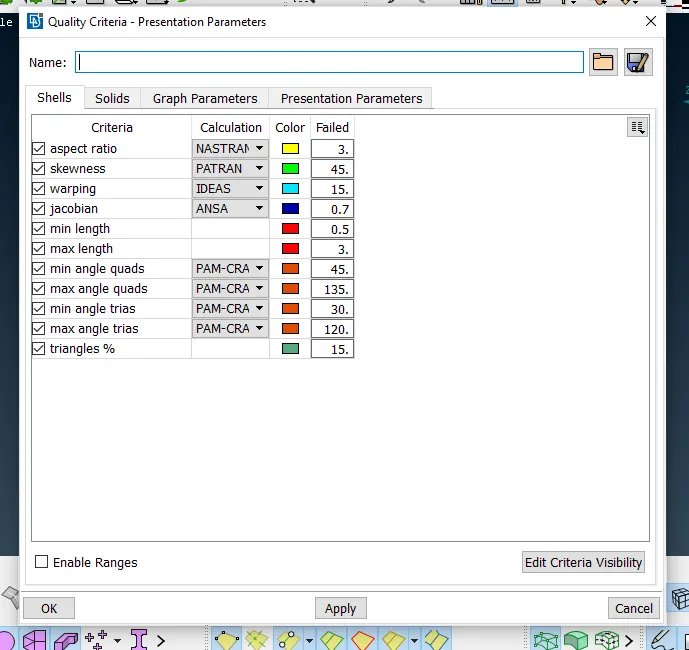
Quality parameters are as follows:
|
Sr no |
Quality Parameter |
Value |
|
1. |
Target/Average length |
1 |
|
2. |
Minimum Length |
0.5 |
|
3. |
Maximum Length |
3 |
|
4. |
Aspect |
3 |
|
5. |
Warpage |
15 |
|
6. |
Skewness |
45 |
|
7. |
Jacobian |
0.7 |
|
8. |
Minimum Quad Angle |
45 |
|
9. |
Maximum Quad Angle |
135 |
|
10. |
Minimum Tria Angle |
30 |
|
11. |
Maximum Tria Angle |
120 |
|
12. |
Tria Percentage |
15 |
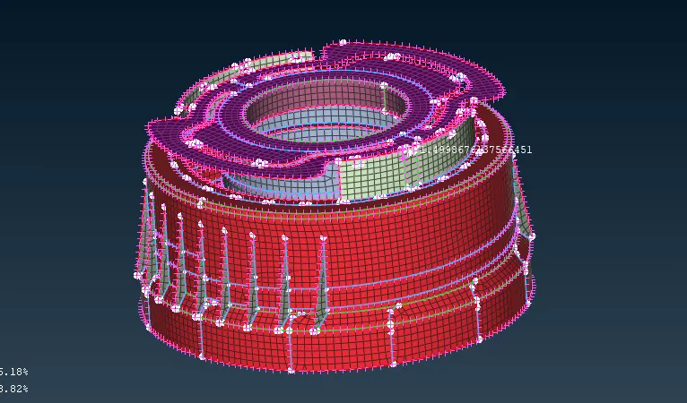
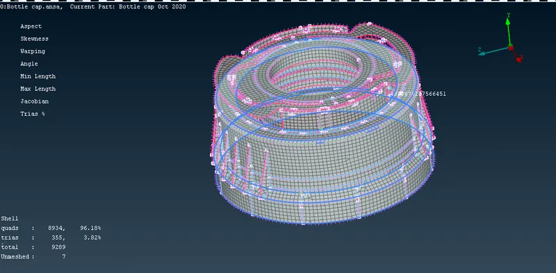
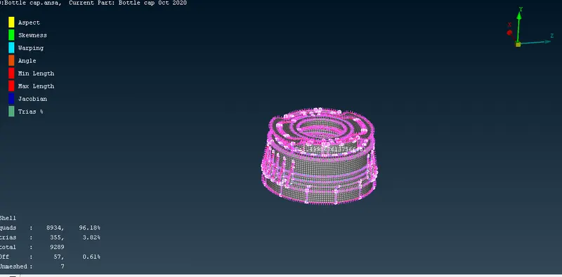
Steps to be followed:
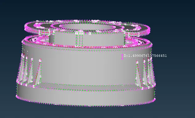
- In the initial step we can proceed with geometry cleanup so as to find any error or dislocations in geometry. So we can use check geometry and execute the various checks, in case if any found then we can solve them by directly clicking on fix option or by rectifying them manually. To improve the resolution of the model we can do that by clicking on length option in the right menu & provide 1mm length.
- Next step is to generate mid surface for the whole body, firstly measure thickness of the various parts so as to have a better idea on which option to select for midsurface.In some parts we can use manual midsurface by choosing “offset” option & also we can create midsurface by “middle tool” or “mid-surface tool”.
- Now to generate midsurface we can isolate the whole body into two parts, one upper part & other body. After measuring thickness we can provide mid surface for each part. As the body contains varying thickness we have to generate PID for each part & provide equivalent thickness for the same. This can be done after meshing.
- To generate midsurface for the threads & features having varying thickness we can use curves middle option from the panel, generate curve & extend the curve to the outer part of the thread. Similarly can be done for features.
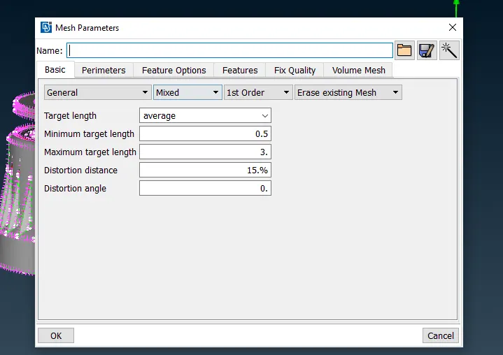
- After creating midsurface now it’s time to provide quality criteria and assign various parameters with min & maximum length.
- Before initiating with meshing we have to toggle all the extra lines which are not necessary. Now as all the lines have been toggled we can start meshing.
- We have to move to mesh module & select best mesh or free mesh in the panel to mesh each surface. We can use reconstruct in the shell mesh to improve the mesh quality. Also to remove trias we can use swap & split option to improve the mesh quality.
- Now check if flow of mesh are good & we satisfy the quality criteria.
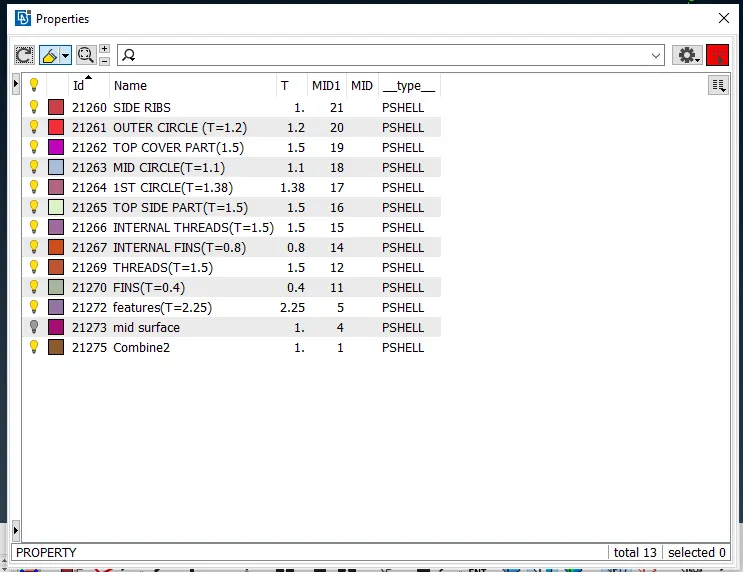
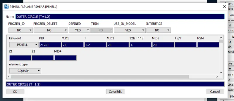
- Next as meshing have been completed we can provide varying thickness from 0.4mm to 2.25 mm as shown.
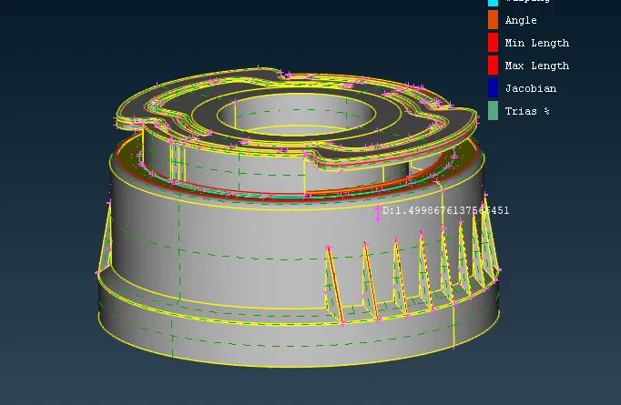
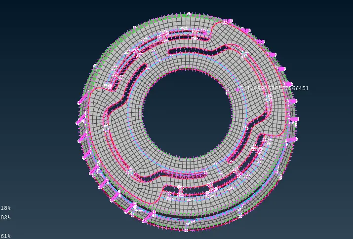
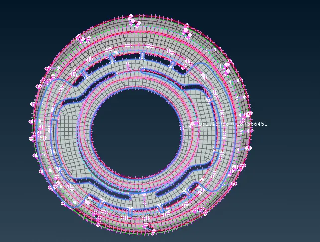
- Finally meshing has been completed for bottle cap model. In the final stage there might be some trias in mesh and off elements in the model but we should make sure that these elements fall under the criteria & don’t exceed them. In Quality criteria we can select draw shell as solid in presentation parameters & check the quality.
We can submit the model now.
Learning Outcomes : Learnt to make use of the middle tool - a third alternative to midsurface creation.
Was able to familiarize with the intersect, extend and project tools which were required for this component.
Also learnt to make use of curves to generate surfaces, be it through manually created curves as well as curves generated with the help of cons.