Week 5.2 - Multi Level Meshing
JORGE LOZANO
Electronic Cooling Simulations using ANSYS ICEPAK
Multi-Level Meshing
Problem Description:
Without any modifications, the model results in about 700,000 elements. Note that this mesh count results from using the non-conformal meshing technique, which reduces mesh bleeding and mesh count. However, this mesh does not fully resolve the fine-level geometric features of the CAD objects. You can reduce the mesh count and improve the mesh resolution on and around the CAD objects by using the multi-level meshing technique. This procedure starts with a coarse background mesh and resolves fine level features through a series of successive mesh refinements. By using multi-level meshing and the uniform mesh parameters feature, you can reduce the mesh count to approximately 500,000 elements and improve mesh resolution.
Generate the Mesh:
- Create non-conformal mesh assembly
- Use mesh separately option with slack values
- Use object parameters
- Use set uniform parameters and use average on 1 assembly, in multi-level meshing tab allow multi-level meshing up to level 2 for the objects.
- Use the same technique of 1
- Generate mesh.
- Observe in mesh reduction
- Do visual inspection
- Check for quality
Process
Given the CAD file, already generated the assemblies 1-3, present a definition of where the critical mesh parameters must be focused or are developing a bleeding effect (having more cells in an axis direction).
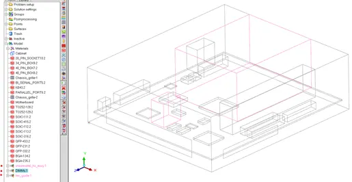
By exploding or expanding all subassemblies, a part visualization can be seen as follows:
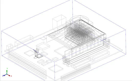
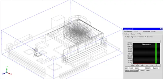
By automatically generating the mesh by using the default conditions and parameters, the total number of elements are 713,114 elements, having a global good skewness.
By selecting a volume which has several pats, a multi-level mesh can be selected to develop a local refinement in the order of 0, 1, 2 and 3 each level a more refined mesh element will be generated.
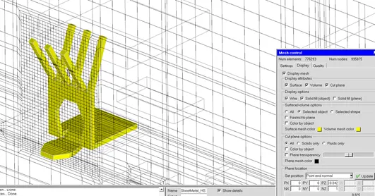
Bleeding is considered as a concentration of small elements, involving cross axis length to be smaller and similar which tend to get darkened as seen in the following image.
A visual analysis must be performed to determine the level in which each assembly, part will be locally refined in a certain level, specifying if it’s a part each maximum axis vertex and its minimum.
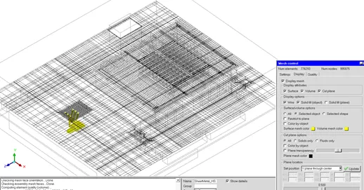
As seen 486,301 elements were obtained when generating a localized muti-level meshing in the section where the fan, case and fins are located, where the selection was its assembly, seeing less bleeding in the same cut plane than the early images, although as seen a level 2 refinement was applied to the yellow part, where a more defined section was obtained, this due to the geometry and its features.
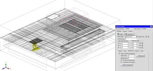
The last iterative mesh generated was able to obtain 480,762 elements, analyzing other elements and its conditions as seen in other planes to determine visually its possibility of usage and its effect in the simulation and physics to be analyzed in.
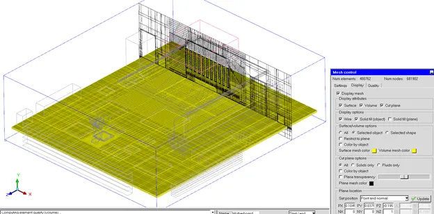
The mesh quality was analyzed in every iteration, due to its importance the skewness condition is plotted and selected, having a seen a good mesh it’s possible to continue and approve the mesh.
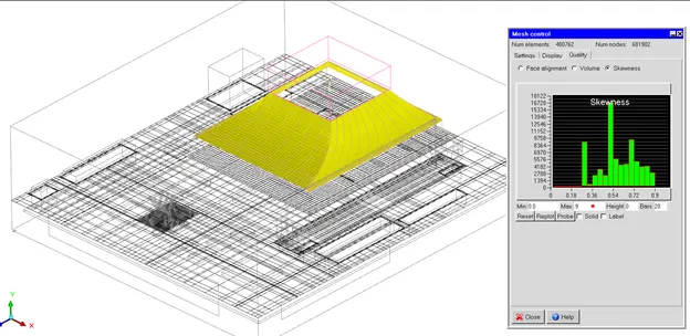
By refining the histogram bar up to its maximum value of 0.9 a more defined and self-explanatory post processing quality mesh analyzer can be seen to determine the following step and locate the areas where the parameters can be redefined.
Conclusion
An optimized mesh analysis was performed reducing 48.33% the initial elements obtained by the initial generated mesh, having a gradual iteration system where the quality, geometric resemblance, and a bleeding effect in the three planes are analyzed to obtain a well-defined mesh.