Week 5.1 - Non-Conformal Meshing and Solving a Cold plate model
Cold plate model:
Cold plates are used to cool components with heat fluxes of around 100 W/cm2. The power electronic cooling library contains models for cold plates and heat dissipation models for some power electronic components.
Thermal management for power electronics is essential in order to provide efficient and durable components. Different cooling technologies are used to remove the dissipated heat from the component depending on the heat flux and the level of power electronics integration.
The cold plate model can be used in the pre-design phase to predict the junction temperature distribution of several power modules placed on one cold plate. The important factors to determine the temperature distribution are the heat conduction in the solid part of the plate and the convective heat transfer in the tube or channel.
Problem statement:
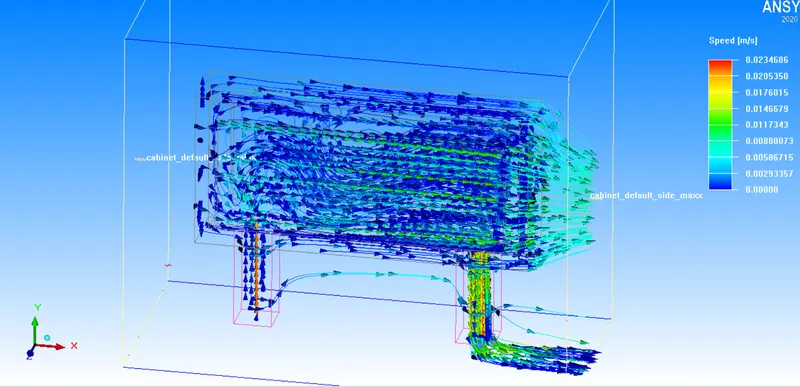
The model setup is shown in figure 5.1: The model includes two heated plates, cooled by water circulating inside the cold-plate cavity, as well as by air driven by natural convection externally. Separately meshed assemblies will be employed to reduce the overall mesh count in the domain.
Cabinet Size: 400 mm X 300 mm X 200 mm
Cold plate solid block: start (50 mm, 80mm, 70 mm), End (350mm, 220 mm, 130 mm) made of aluminum extruded
Cold plate fluid block: start (60 mm 90mm, 80 mm), End (340mm, 210 mm, 120mm)
Incoming pipe: thickness : 5mm, connected @ (100mm, 0 mm, 100mm) and radius 15 mm, the inlet water velocity is 0.2 m/s
Outgoing pipe: thickness : 5mm, connected @ (300mm, 0 mm, 100mm) and radius 15 mm
Plate 1: conducting thick 10mm, 200W, located at 60mm having dim (260 mm X 100 mm) in Z plane
Plate 2: conducting thick 10mm, 200W, located at 130mm having dim (260 mm X 100 mm) in Z plane
Cabinet opening: MinX and Max X
Geometrical creation:
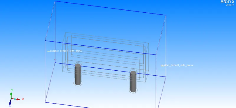
Assembly 1 settings:
Fluid a, solid a, opening 1
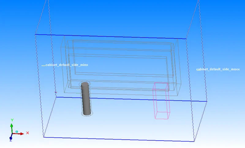
Slack settings for assembly meshing
Min x = 2mm
Max x =2mm
Min y= 0
Max y= 0
Min z = 2mm
Max z = 2mm
Mesh type
Maximum element size in x = 2mm
Maximum element size in y = 5mm
Maximum element size in z = 2mm
Min gap x = 0.02mm
Min gap y = 0.05mm
Min gap z = 0.02mm
Assembly 2 settings:
Fluid b, solid b, opening 2
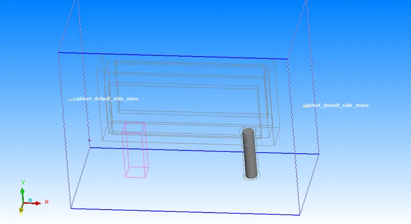
Slack settings for assembly meshing
Min x = 2mm
Max x =2mm
Min y= 0
Max y= 0
Min z = 2mm
Max z = 2mm
Mesh type
Maximum element size in x = 2mm
Maximum element size in y = 5mm
Maximum element size in z = 2mm
Min gap x = 0.02mm
Min gap y = 0.05mm
Min gap z = 0.02mm
Assembly 3 settings:
Assembly 1, assembly 2, plate 1, plate 2
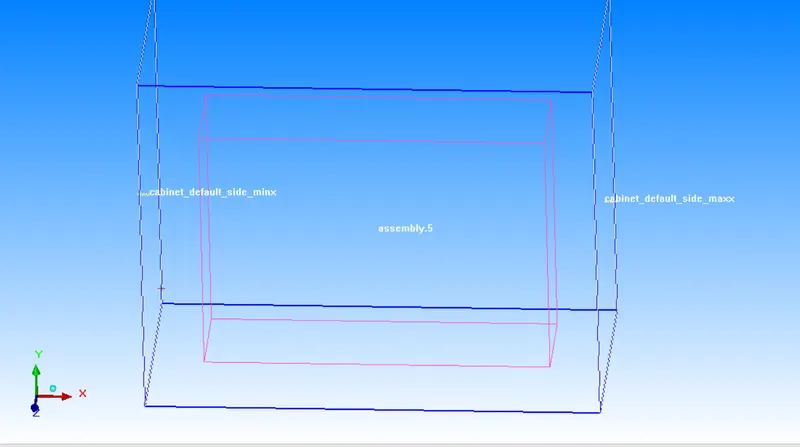
Slack settings for assembly meshing
Min x = 2mm
Max x =2mm
Min y= 0
Max y= 0
Min z = 2mm
Max z = 2mm
Mesh type
Maximum element size in x = 10mm
Maximum element size in y = 7.5mm
Maximum element size in z = 5mm
Min gap x = 0.1mm
Min gap y = 0.075mm
Min gap z = 0.05mm
Global mesh settings:
Maximum element size in x = 20mm
Maximum element size in y = 15mm
Maximum element size in z = 10mm
Min gap x = 0.2mm
Min gap y = 0.15mm
Min gap z = 0.1mm
Mesh parameter: normal
Mesh check:

Mesh verification:
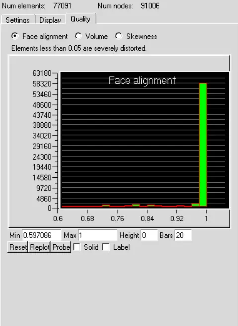
Face alignment:
Measures the mesh quality by face alignment index.
The value of face alignment ranges from 0 to 1. Value greater than 0.1 is preferred and greater than 0.15 is better.
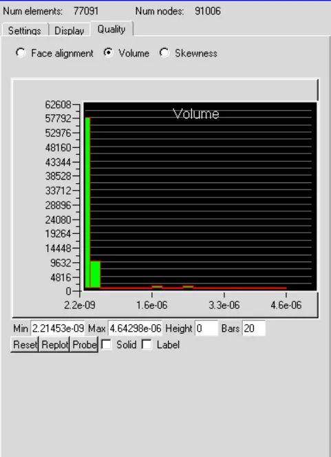
Volume:
Preferable volume mesh should be 1e-12 for single precision and 1e-15 for double precision.
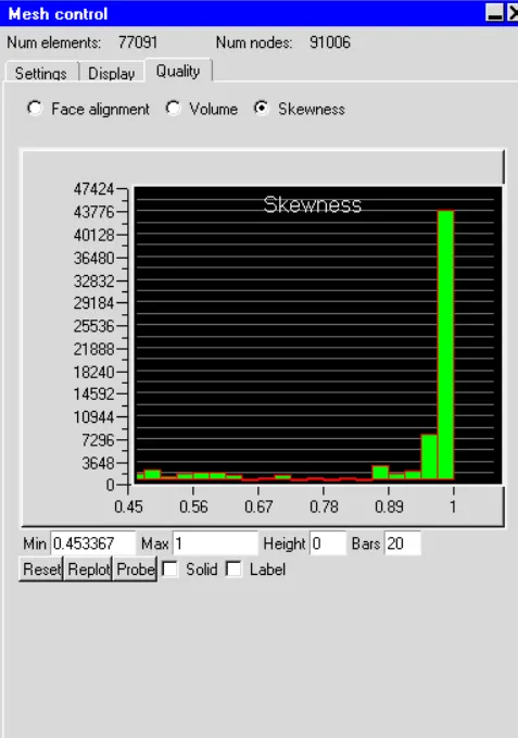
Skewness:
It determines the deviation of the mesh from its ideal shape.
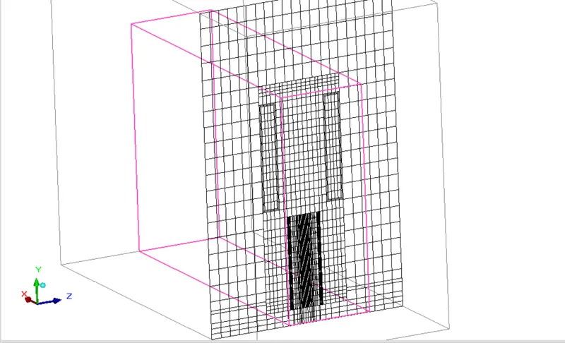
Mesh display in x direction
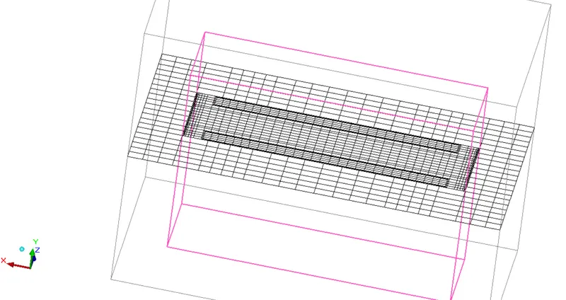
Mesh display in y direction
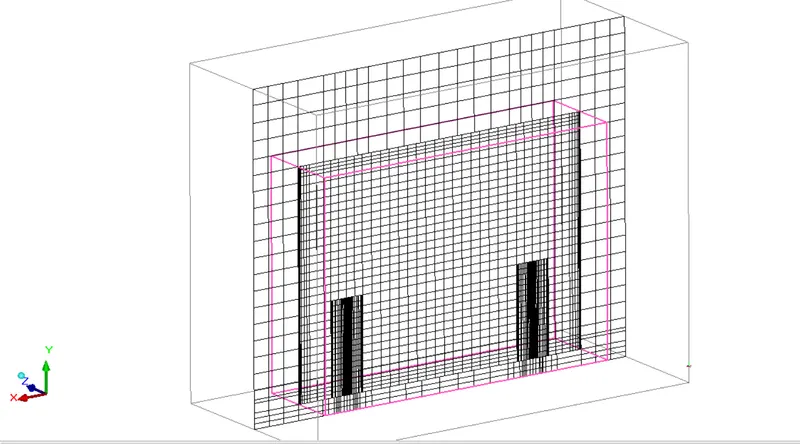
Mesh display in z direction
Solver setting:
No of iteration-1000
Turbulence model-zero equation model
Natural convection in x direction
Convergence criteria-0.001
Post processing:
Plane cut
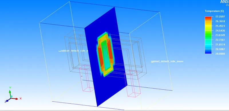
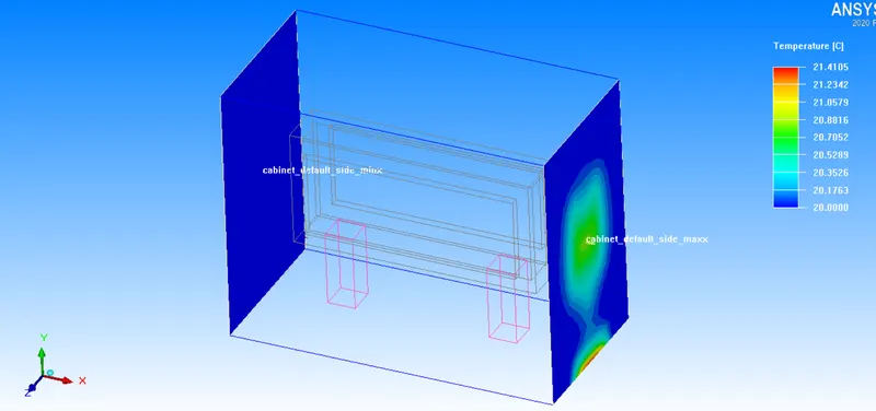
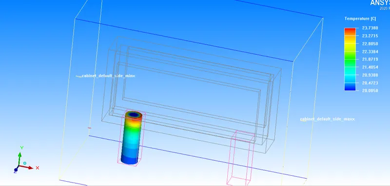
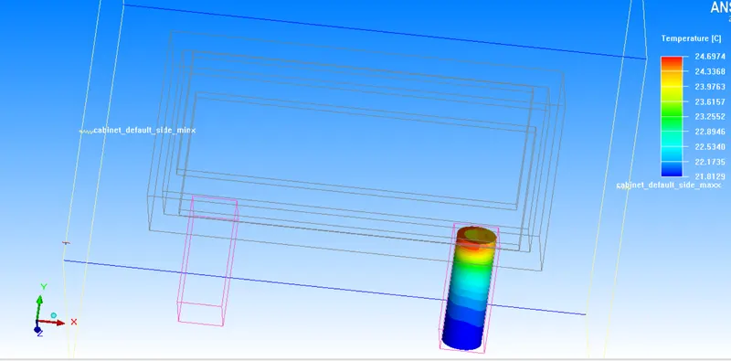
Temperature contour in x direction
Temperature contour in y direction
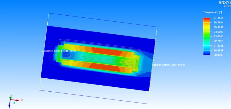
Temperature contour in z direction
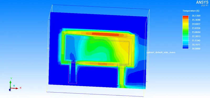
Velocity contour in x direction
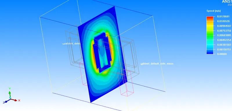
Velocity contour in y direction
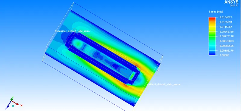
Velocity contour in z direction
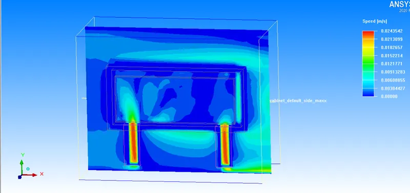
Face object
Cabinet opening
Inlet pipe
Outlet pipe
Heated plate
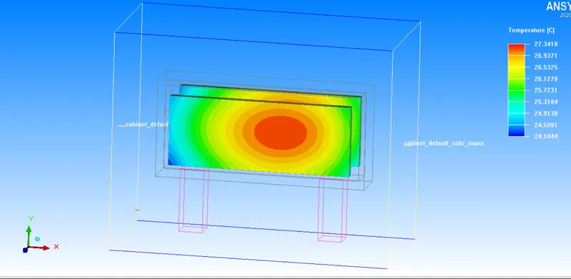
Fluid block
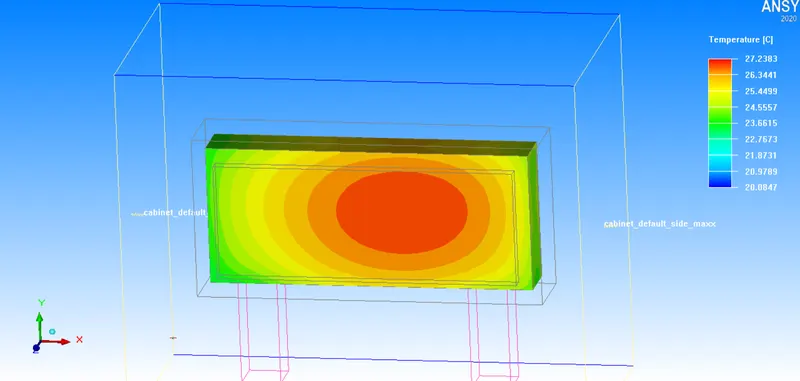
Solid block
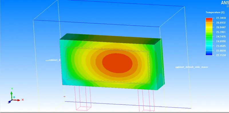
Vector plot
Velocity plot