Week 4 -Wire Bending Challenge
WIRE BENDING CHALLENGE
Objective: -
- We will have to perform an analysis to simulate the bending of a wire in ANSYS.We will assign non linear materials for the wire-
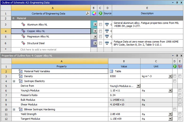
- Copper Alloy NL
- Aluminium Alloy NL
- Magnesium Alloy NL
ii. Find out the equivalent stress and equivalent strain on the wire.
Procedure: -
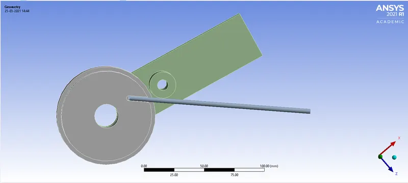
- Import the geometry and assign copper alloy non-linear material to the wire. We will follow the same procedure to assign different materials to the wire for analysis.
Copper alloy NL-
Geometry-
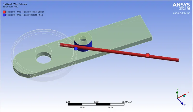
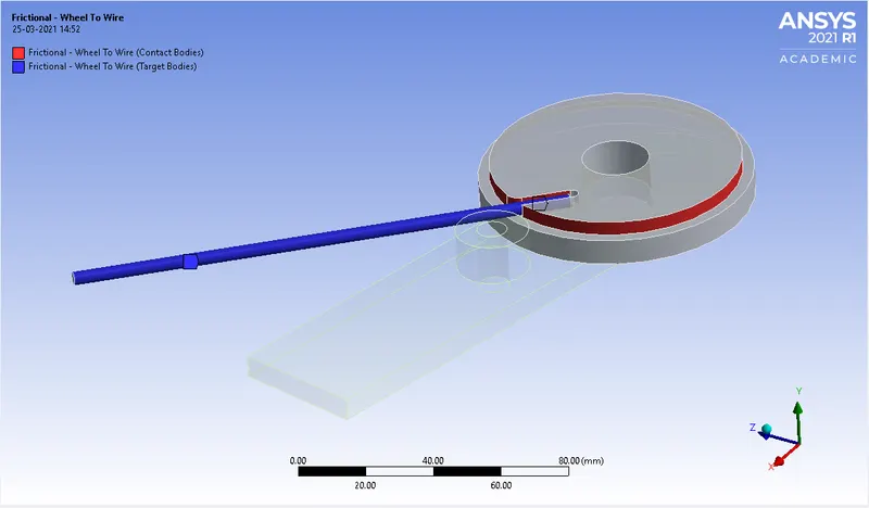
Connections-
Friction contacts are provided between the lever-wire and Wheel-wire with a frictional coefficient set to 0.2.Contact and target body assignment must be taken care of while providing contacts.
Formulation: Augmented Lagrange.
Normal Stiffness: factor.
Normal Stiffness Factor: 0.1.
Update Stiffness: Each Iteration.
Interface Treatment: Add Offset, Ramped Effects.
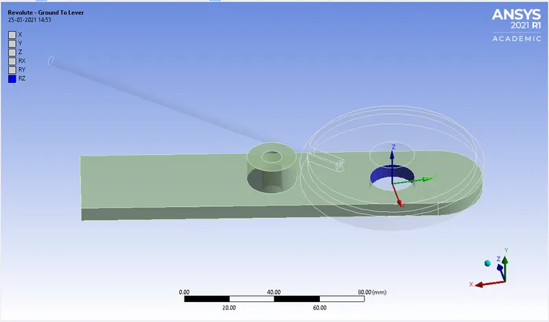
Revolute Joint-
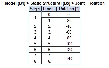
Revolute Joint is provided to the lever that will perform the bending of the wire.The rotation values can be traced from the below fig-
MESHING-
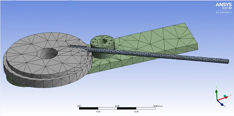
The meshing of the model is done using tetrahedron elements.Wire, wheel and lever has importance regions that will come in contact with each other while moving.We have to mesh these areas with an element size of 2.2mm and also another face sizing between the wire and the wheel with an element size of 0.8 mm using sphere of influence.
ANALYSIS SETTINGS-
An analysis is performed using 8 steps with Auto Time stepping ON and the type of solver we use is direct which is one of the many methods to solve simultaneous equations and with additional settings provided as shown below.
1st step:
Initial time – 0.1
Minimum Time step – 1E-2
Maximum Time step – 0.2
and switching to yes in the Output Controls.
2-8 steps:
Turn on the Carry over time step
Minimum Time step – 1E-2
Maximum Time step – 1
BOUNDARY CONDITIONS:
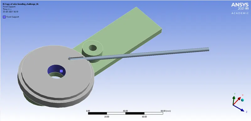
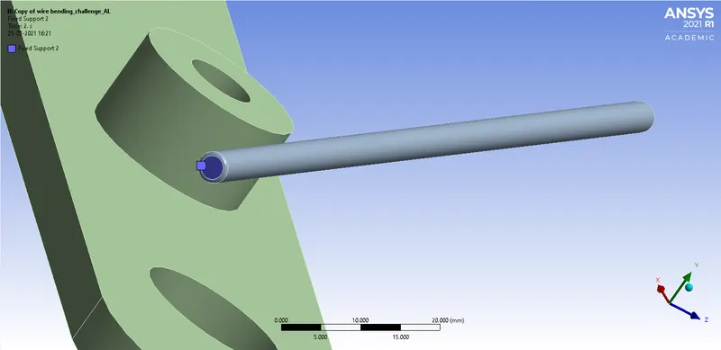
Fixed support is applied to the wheel and at the tip of the wire to restrict the movement of the wire during the simulation which otherwise would result in an error.
Fixed Support on the Wheel-
Fixed Support at Tip of the wire-
Results-
Case 1: Copper Alloy NL:
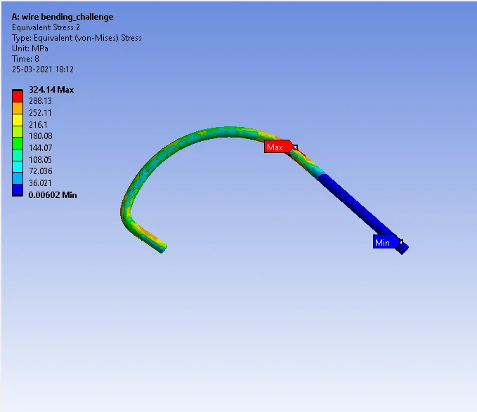
Equivalent stress in wire for copper alloy NL
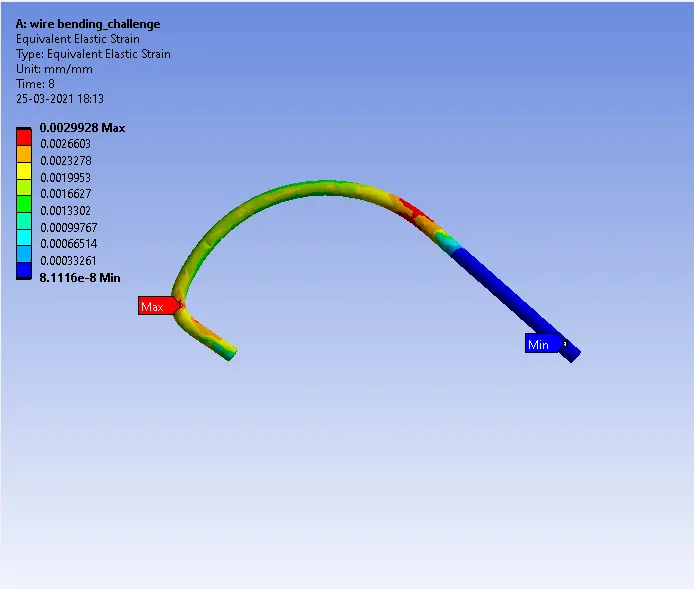
Equivalent strain in wire for copper alloy NL
CASE-II: Aluminium alloy NL
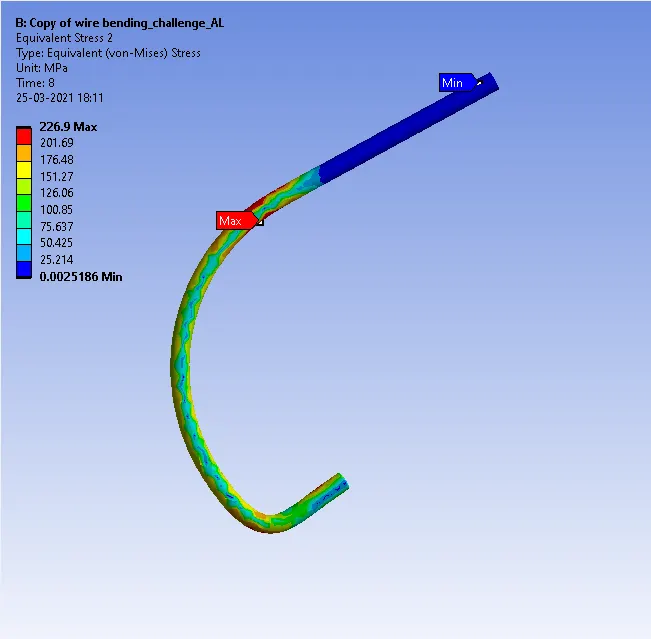
Equivalent stress in wire for aluminium alloy NL
Equivalent strain in wire for aluminium alloy NL
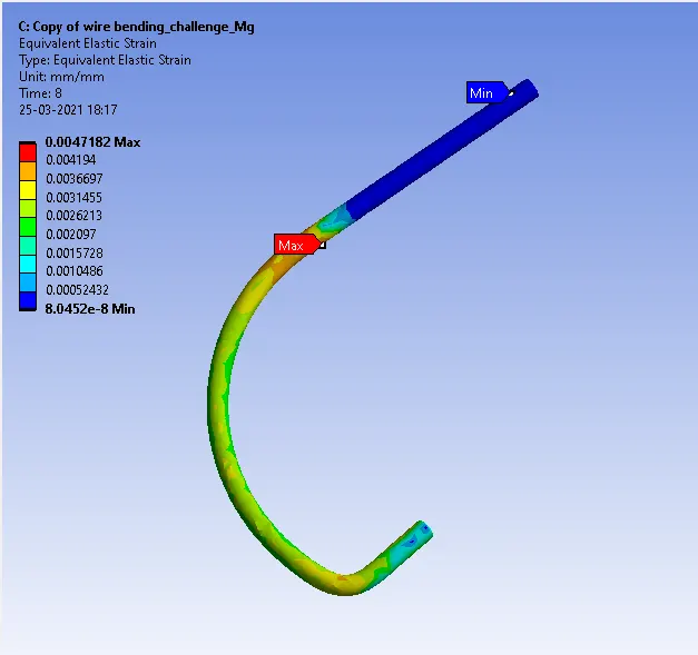
CASE-III: Magnesium alloy NL
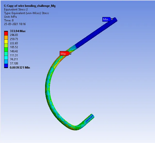
Equivalent stress in wire for Magnesium alloy NL
Equivalent strain in wire for Magnesium alloy NL
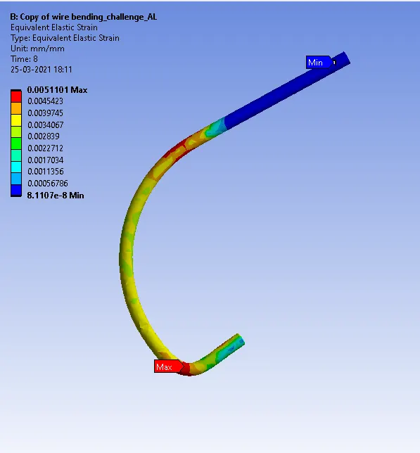 \
\
Tabular data: -
| Sr.No. | Results | Maximum Equivalent stress (MPa) | Equivalent Strain |
| 1 | Case-I | 324.14 | 0.00299 |
| 2 | Case-II | 333.94 | 0.00471 |
| 3 | Case-III | 226.9 | 0.00511 |
From the Above, we can summarize that copper has the least strain due to its high Young’s modulus compared to other material but experiences the highest stress and magnesium with the least stress, whose yield strength compared to Aluminium Alloy and Copper Alloy is less.
Conclusion: -
- To refine meshing at an area which is of importance using the sphere of influence.
- Setting fixed supports and joint load conditions.
- Setting up Analysis setting for Non-Linear Analysis and time-step for simulation.