Week 4 -Wire Bending Challenge
AIM : -
PERFORM THE STRUCTURAL ANALYSIS OF A WIRE BENDING OPERATION USING WIRE DIFFERENT WIRE MATERIALS AND COMPARE THE EQUIVALENT STRESS AND EQUIVALENT STRAIN FOR THE WIRE AND COMPARE THESE RESULTS FOR EACH MATERIAL.
Objectives:
Perform Static Structural analysis for the wire bending operation taking the wire material as:
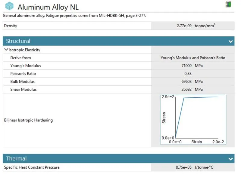
i) Aluminium Alloy NL
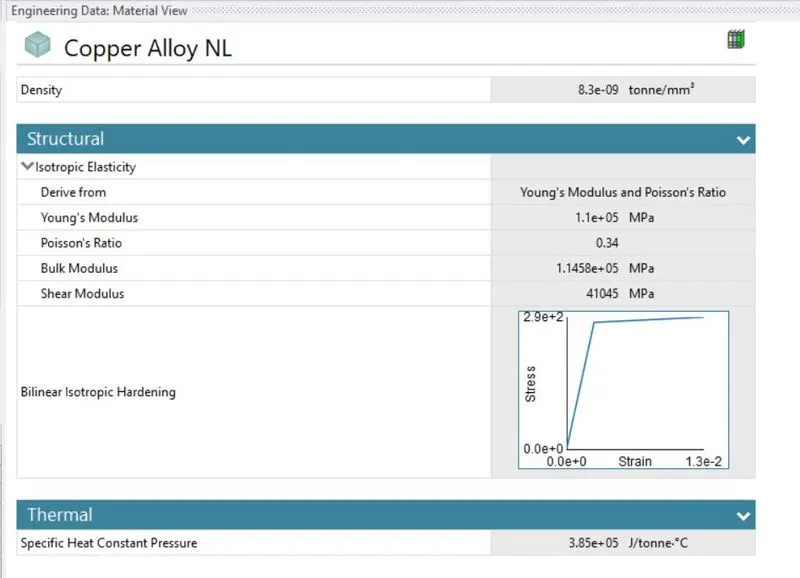
ii) Copper Alloy NL
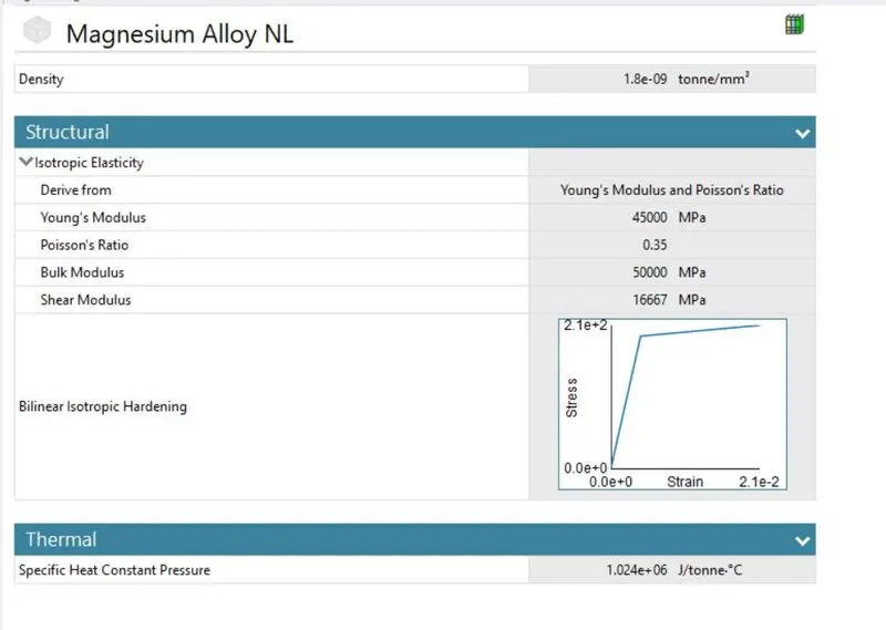
iii) Magnesium Alloy NL
Compare the Equivalent Stress and Strain of the wire for each case.
Procedure :-
- select the Static Structural analysis from the Analysis Systems.
- Double-click on Engineering Data, go to Engineering Data Sources and go to the General Non-Linear section. Choose the required materials and add them to the project environment.
- Next, import the geometry into the project space and double-click on Geometry to launch the SpaceClaim and load the geometry in it. The geometry will look like this:
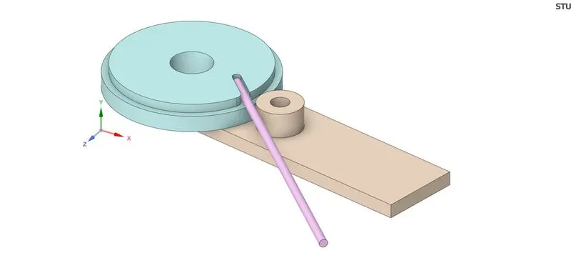
Checking for any abnormalities if present in the geometry.
-
Next, right-click on Model and select Edit to launch the Mechanical Module and load the geometry in the module.
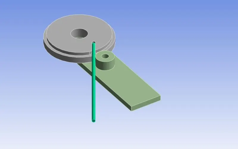
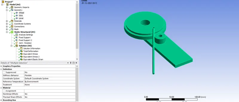
After it, expand the Geometry option and rename the parts.
Now, select the WIRE and assign the Copper Alloy NL material to it.
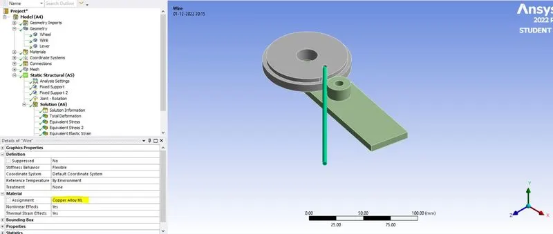
Material Selection :-
i) Copper Alloy NL
ii)Magnesium Alloy NL
iii) Aluminum Alloy NL:-
Connection Set-Up :-
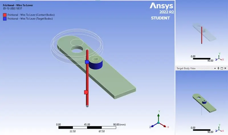
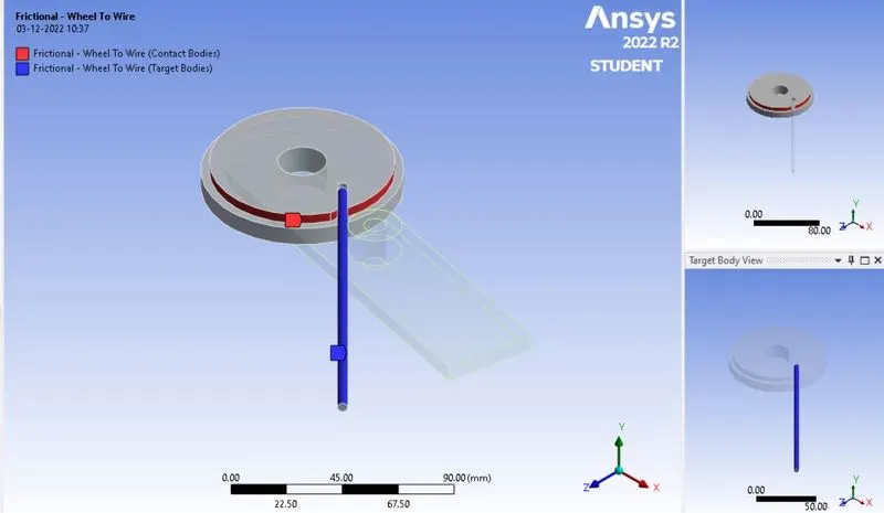
Frictional Contact between Wire and Lever :
Select the wire outer surface as a Contact Body and Select the lever contact face as a Target Body.
Keep Contact type is Frictional and coefficient of friction is 0.2.
Keep "Augmented Lagrange" for Formulation type .
Enable "Factor" for Normal Stiffness and the corresponding value is 0.1.
Keep "Each Iteration" for Update Stiffness.
Keep "Add Offset, Ramped Effects" for Interface Treatment.
Frictional Contact between Wheel and Wire :
Select the Wheel Contact face as a Contact body and Select the wire outer face as a target body.
Similarly, Keep all those things remains same like as we did in previous one.
Revolute Joint for Lever :
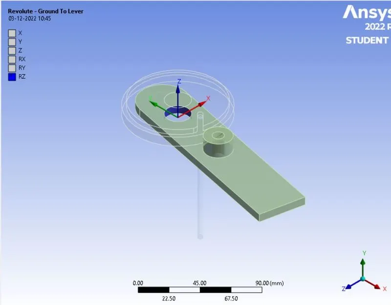
- Create a New Joints, select the inner face of the Lever and then select "Body to Ground " instead of "Body to Body" as a connection Type.
- Select "Revolute" as a type of joint, it will automatically constraint in all possible motions except revolution about an Z axis.
Meshing :-
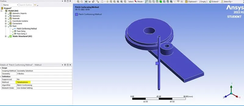
First, right-click on Mesh, go to Insert, and select Method. Select all the bodies in the geometry click Apply and then in Method select Tetrahedrons.
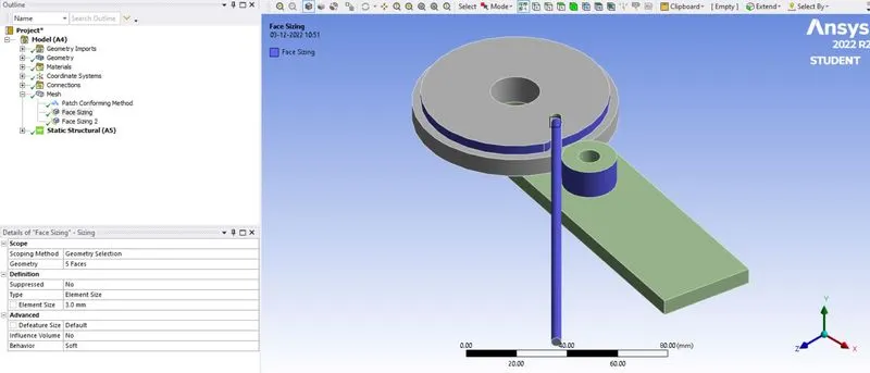
Next, choose Sizing and select the surfaces shown in the figure below hit Apply. Enter the Element Size as 3.0 mm.
Now, for more stress concentration area add sphere of Influence as shown in below snap, Select mesh size as 0.8 mm
Complete Mesh model :-
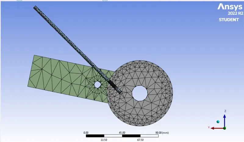
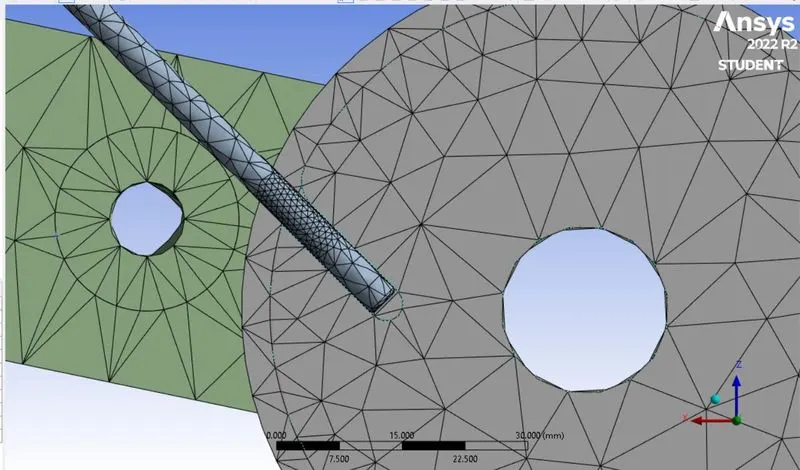
Mesh Quality (Mesh matric) :-
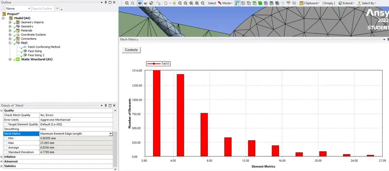
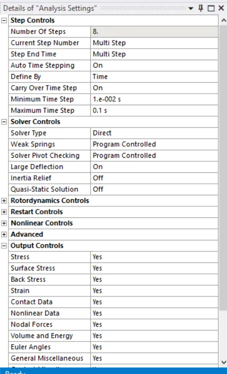
Set-Up analysis Setting :-
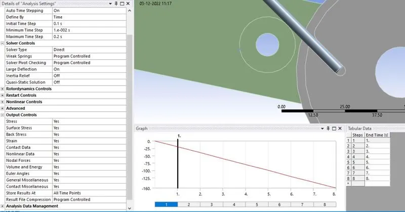
For first Step:
Auto Time Stepping = ON
Defined By = Time
Initial Time Step = 0.1 sec.
Minimum Time Step = 0.01 sec.
Maximum Time Step = 0.2 sec.
In Solver Controls,
Solver Type = Direct.
Weak Springs = Program Controlled.
Large Deflection = ON.
Turn ON all the Output Controls options.
For the rest Steps:
Auto Time Stepping = ON
Defined By = Time
Carry Over Time Step = ON
Minimum Time Step = 0.01 sec.
Maximum Time Step = 1 sec.
In Solver Controls,
Solver Type = Direct.
Weak Springs = Program Controlled.
Large Deflection = ON.
Turn ON all the Output Controls options.
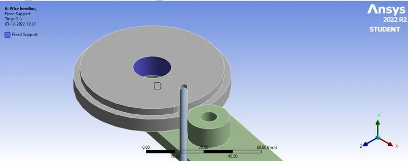
Set-Up Boundary Conditions :-
The inner surface of the WHEEL is fixed by right-clicking on Analysis Settings and going to the Insert option and selecting the Fixed Support.
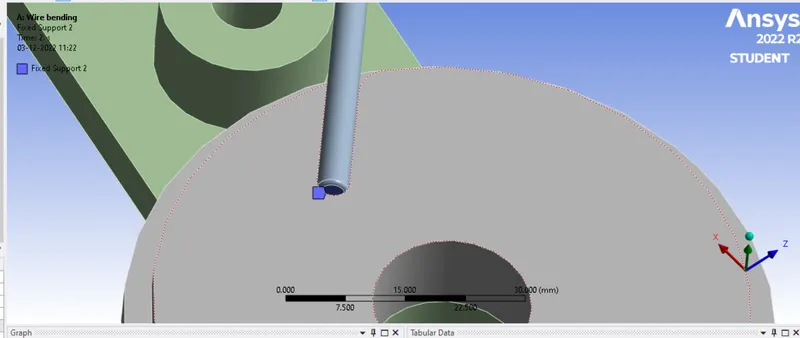
Fixed one end of wire to constrain motion of wire :-
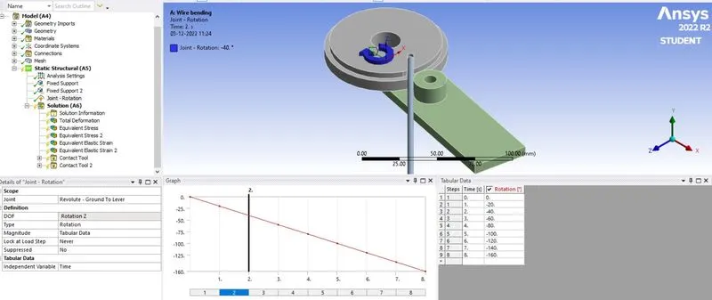
Provide Revolute Joint on LEVER:
Now, give a revolute joint to the LEVER, right-click on Connections, go to Insert, and select the Joint Load. Change the Connection Type as Body-Ground and Type as Revolute.
Result :-
Case-1 :-
Aluminium Alloy NL :-
Equivalent Stress :-
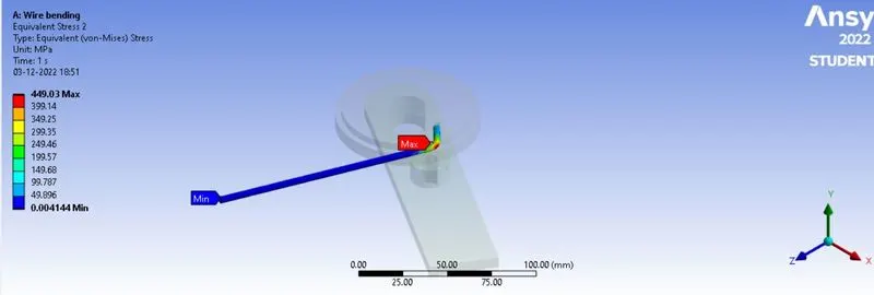
Max. Value 451.95 MPa
Equivalent strain :-
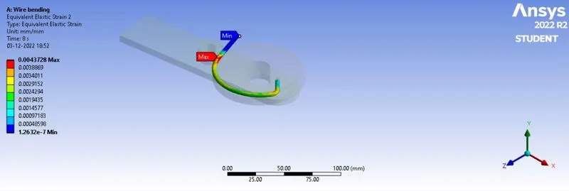
Max. Value :-0.0043 mm/mm
Case-2 :-
Copper Alloy NL :-
Equivalent Stress :-
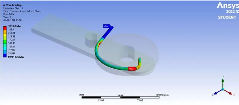
Max. Value 651.38 MPa
Equivalent strain :-
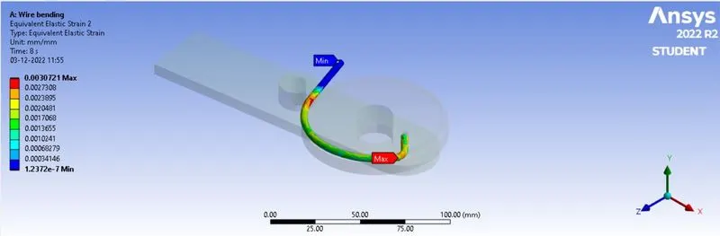
Max. Value 6.425e-003 mm/mm
Case-3 :-
Magnesium Alloy NL :-
Equivalent Stress :-
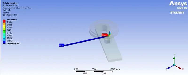
Max. Value 484.99 MPa
Equivalent strain :-
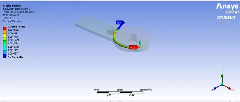
Max. Value 1.0818e-002 mm/mm
Conclusion :-
1. The Copper Alloy is most difficult to deform since the stress required to bend the copper wire is maximum in all three wires. Aluminium Alloy wire is readily deformable with the least stress required.
2. The Magnesium Alloy wire shows the highest amount of strain developed among the three wires, followed by Copper wire and then Aluminium wire with the least of all.
3. from the above results, the Aluminium Alloy NL wire is the best pick for the wire since it requires less force to get deformed. The Magnesium Alloy NL should not be taken since for the similar loads as applied on Aluminium Alloy, the Magnesium wire will exhibit a huge amount of strains developed within it. This may lead to premature failure of the wire.