Week 4 -Wire Bending Challenge
Wire Bending Simulation
Objective: To run the simulation of wire bending using three different materials such as Aluminum alloy, Copper alloy, Magnesium alloy & compare their results.
Case setup & Execution:
- Open Ansys workbench & select static structural for simulation.
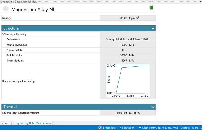
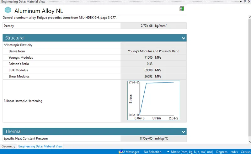
- Select Engineering material & insert three material such as Aluminum, Copper & Magnesium.
- Choose geometry tab and import the file, edit the same in space claim. Check if all the contact and geometry is good and can be used for further simulation.
- Update the model and edit the same. Rename the parts with wheel wire & lever.
- In connections, contacts delete first two contact and ten select the last contact of wheel & level. Duplicate the contact and flip the contact and target for the 2nd Now select both the contact and provide a frictional value of 0.2, formulation as augmented Lagrange, Normal stiffness as 0.1, update stiffness to each iteration and interface treatment as adjust to touch.
- Insert a revolute joint choosing body to ground and select the lever for the same.
- Now moving to mesh select solid selector choose all three geometry and choose tetrahedrons. Choose the element size as required and look if the mesh look fine.
- As the wire and lever will be in contact insert a new coordinate system and provide a much finer mesh so that solution is converged in contact points. Insert a sphere of influence near the contact. Choose the radius and element size as required. Generate mesh.
- Next in analysis setting select no of steps as 8 & insert time step as required for various material. Select large deflection to be on and weak spring as program controlled. In this we have provided various time values for the first step and various values for remaining 7 steps. In output control select all the control to yes.
- Now in support insert a fix support and select the wheel so that it will be fixed. Insert a fix support and again select the top part of wire so that wire does not slip out.
- Insert a joint load and select lever. Also provide rotation to the lever in degree. Insert various degree of rotation for different material.
- Now in final step choose various results such as total deformation, Equivalent stress, and Equivalent strain as required. Hit Solve.
Results:
|
Sr No |
Material |
Total Deformation (mm)(max) |
Equivalent Strain (max) |
Equivalent stress (Mpa)(max) |
|
1. |
Copper Alloy |
262.64 max |
0.003198 |
348.91 max |
|
2. |
Magnesium Alloy |
262.64 max |
0.005369 |
240.83 max |
|
3. |
Aluminum Alloy |
223.49 max |
0.004379 |
309.74 max |
Wire Bending Simulation
Objective: To run the simulation of wire bending using three different materials such as Aluminum alloy, Copper alloy, Magnesium alloy & compare their results.
Case setup & Execution:
- Open Ansys workbench & select static structural for simulation.
- Select Engineering material & insert three material such as Aluminum, Copper & Magnesium.
- Choose geometry tab and import the file, edit the same in space claim. Check if all the contact and geometry is good and can be used for further simulation.
- Update the model and edit the same. Rename the parts with wheel wire & lever.
- In connections, contacts delete first two contact and ten select the last contact of wheel & level. Duplicate the contact and flip the contact and target for the 2nd Now select both the contact and provide a frictional value of 0.2, formulation as augmented Lagrange, Normal stiffness as 0.1, update stiffness to each iteration and interface treatment as adjust to touch.
- Insert a revolute joint choosing body to ground and select the lever for the same.
- Now moving to mesh select solid selector choose all three geometry and choose tetrahedrons. Choose the element size as required and look if the mesh look fine.
- As the wire and lever will be in contact insert a new coordinate system and provide a much finer mesh so that solution is converged in contact points. Insert a sphere of influence near the contact. Choose the radius and element size as required. Generate mesh.
- Next in analysis setting select no of steps as 8 & insert time step as required for various material. Select large deflection to be on and weak spring as program controlled. In this we have provided various time values for the first step and various values for remaining 7 steps. In output control select all the control to yes.
- Now in support insert a fix support and select the wheel so that it will be fixed. Insert a fix support and again select the top part of wire so that wire does not slip out.
- Insert a joint load and select lever. Also provide rotation to the lever in degree. Insert various degree of rotation for different material.
- Now in final step choose various results such as total deformation, Equivalent stress, and Equivalent strain as required. Hit Solve.
Results:
|
Sr No |
Material |
Total Deformation (mm)(max) |
Equivalent Strain (max) |
Equivalent stress (Mpa)(max) |
|
1. |
Copper Alloy |
262.64 max |
0.003198 |
348.91 max |
|
2. |
Magnesium Alloy |
262.64 max |
0.005369 |
240.83 max |
|
3. |
Aluminum Alloy |
223.49 max |
0.004379 |
309.74 max |
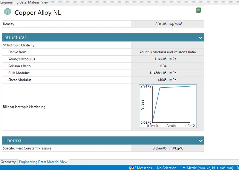
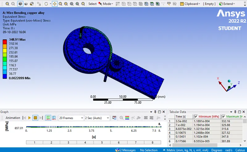
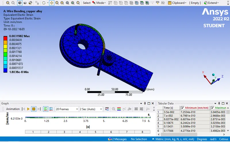
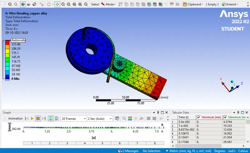
Case 1: In this case we have selected the material of wire rope as copper alloy. From the results it’s been observed that total deformation is 262.64 max. Equivalent strain developed is 0.003198 max & Equivalent stress generated is 348.91 max.
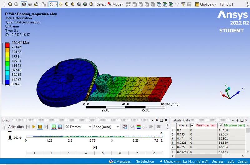
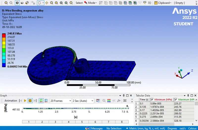
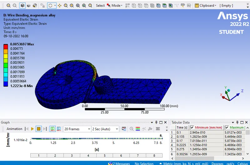
Case 2: In this case we have selected the material of wire rope as magnesium alloy. From the results it’s been observed that total deformation is 262.64 max. Equivalent strain developed is 0.005369 max & Equivalent stress generated is 240.83 max.
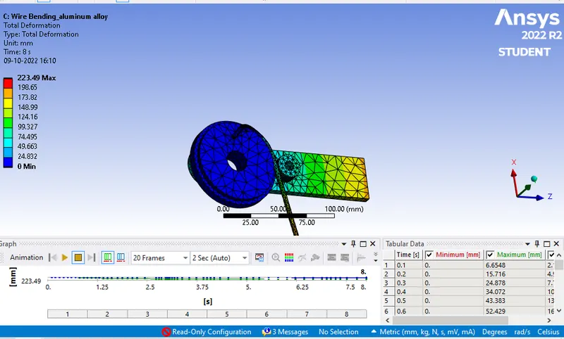
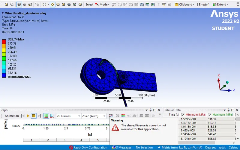
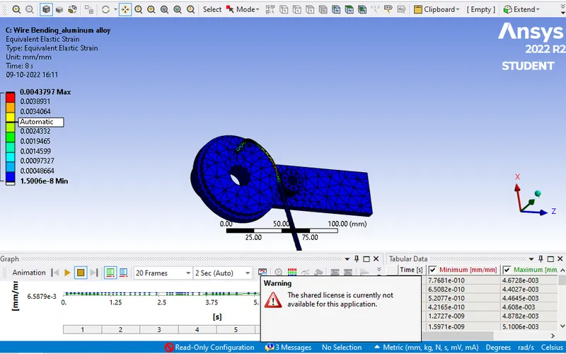
Case 3: In this case we have selected the material of wire rope as aluminum alloy. From the results it’s been observed that total deformation is 223.49max. Equivalent strain developed is 0.004379 max & Equivalent stress generated is 309.74 max.
Conclusion:
We have selected three different material having various density in simulation. To run the simulation for aluminum material we have reduce the rotation to 10 deg in each step. We also have to change the boundary condition for various material. So with respect to same maximum stress is developed in copper material then following aluminum and at last magnesium alloy. Max stress is developed in magnesium because it has the least young’s modulus. So we can choose the material depending on various conditions & parameters.
Case 1: In this case we have selected the material of wire rope as copper alloy. From the results it’s been observed that total deformation is 262.64 max. Equivalent strain developed is 0.003198 max & Equivalent stress generated is 348.91 max.
Case 2: In this case we have selected the material of wire rope as magnesium alloy. From the results it’s been observed that total deformation is 262.64 max. Equivalent strain developed is 0.005369 max & Equivalent stress generated is 240.83 max.
Case 3: In this case we have selected the material of wire rope as aluminum alloy. From the results it’s been observed that total deformation is 223.49max. Equivalent strain developed is 0.004379 max & Equivalent stress generated is 309.74 max.
Conclusion:
We have selected three different material having various density in simulation. To run the simulation for aluminum material we have reduce the rotation to 10 deg in each step. We also have to change the boundary condition for various material. So with respect to same maximum stress is developed in copper material then following aluminum and at last magnesium alloy. Max stress is developed in magnesium because it has the least young’s modulus. So we can choose the material depending on various conditions & parameters.
Note - All images are attached above for reference. Also the simulation file is attached in required format.