Week 4- Rolling operation
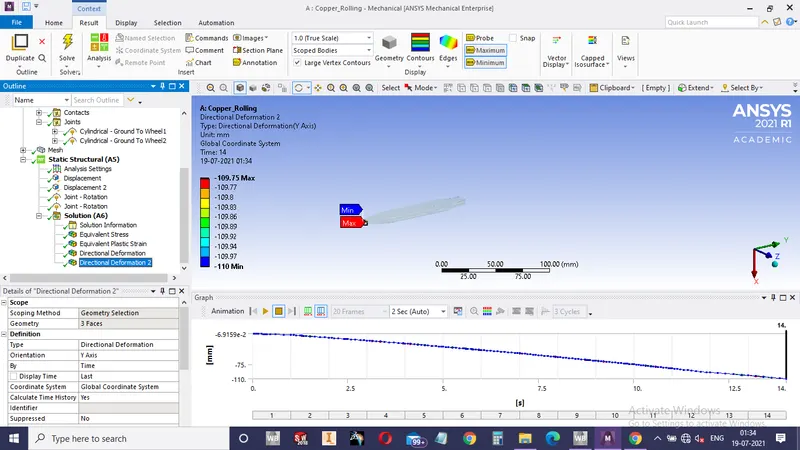
Objective: To simulate the rolling operation on a copper workpiece by increasing the length of the workpiece by 60mm and decrease its size on both sides by 8mm. To run the simulation for 14 steps and prove that the edge of the workpiece is displaced by 90mm.
Setup:
Engineering data:
Copper alloy NL
Geometry:
- exported file of copper_rolling.stp
- Edit Geometry in spaceclaim: Increase length of workpiece by 60mm and decrease the width by 8mm on each side of workpiece
Model:
Geometry: renamed parts as wheel1, wheel2, workpiece
Material: no change
Coordinate system: no change
Connections:
Contacts:
- Frictional: Workpiece to Wheel1
- Frictional: Workpiece to Wheel2
Joints:
- Cylindrical: Ground to Wheel1
- Cylindrical: Ground to Wheel2
Mesh:
- Body sizing: 3mm to workpiece
Static structural:
- Analysis setting:
- Number of steps =14
- Large deflection: on
- Stabilization: constant
- Energy dissipation ratio: 0.1
- Force convergence: On
- Output controls: All yes
- Displacement:
- Geometry = 2 faces of workpiece (to avoid slipping)
- X component = free, Y component = tabular data, Z component = free
- Joint-Rotation:
- Cylindrical: Ground to Wheel1
- DOF: Rotation Z
- Type: Rotation
- Magnitude: tabular (clockwise)
- Joint-Rotation:
- Cylindrical: Ground to Wheel2
- DOF: Rotation Z
- Type: Rotation
- Magnitude: tabular (anticlockwise)
Solution:
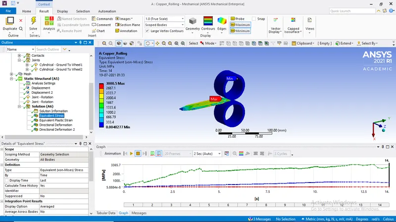
- Equivalent stress
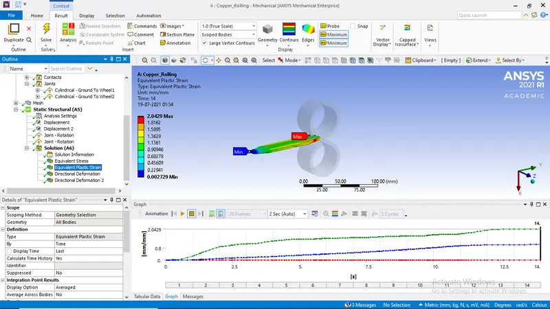
2. Equivalent Plastic strain
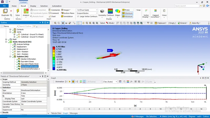
3. Directional Deformation of Side faces
4. Directional Deformation of face in Y direction