Week 4- Rolling operation
OBJECTIVE:
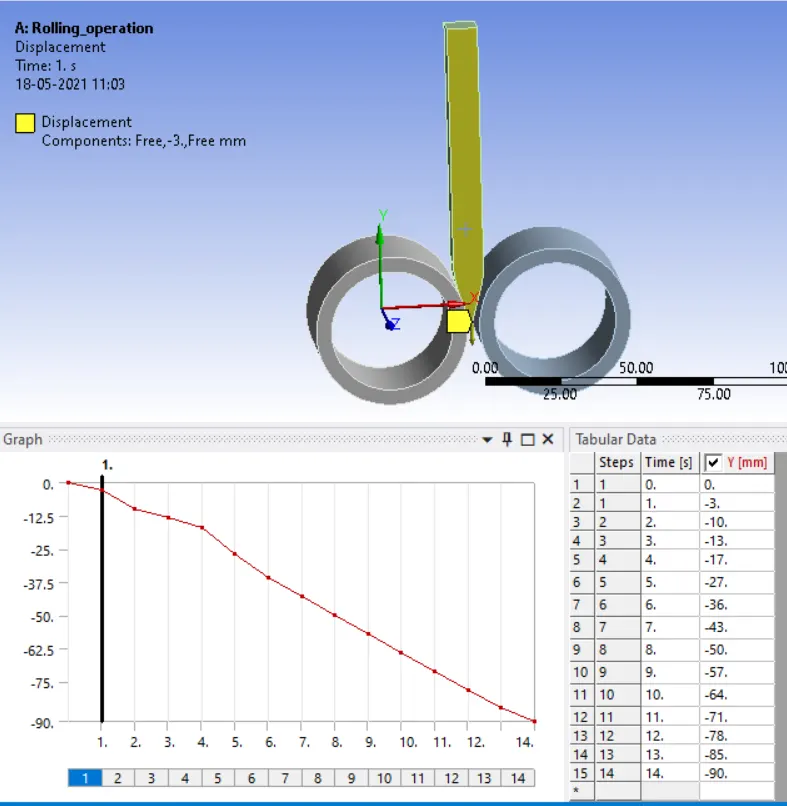
In this challenge, we have to simulate the rolling operation on a workpiece made of copper, by Increase the length of the workpiece by 60mm and decrease its size on both sides by 8mm. Run the simulation for 14 steps of random values for the displacement and ensure that the edge of the workpiece is displaced by 90mm.
PROCEDURE
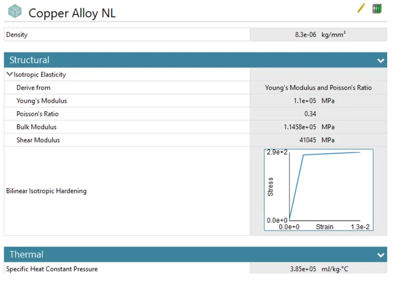
- First, we have to input the engineering materials with required properties or else by creating with required properties.
- Then we have to import our model into Ansys, import the model and open it in space claim so that Ansys will read it.
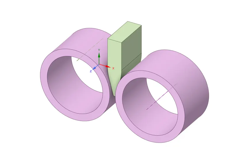
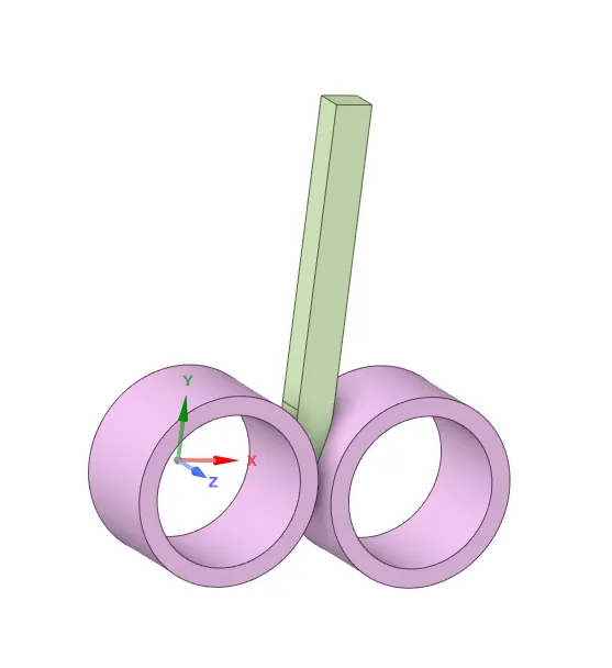
- Increase the length of the workpiece by 60mm and decrease its size on both sides by 8mm
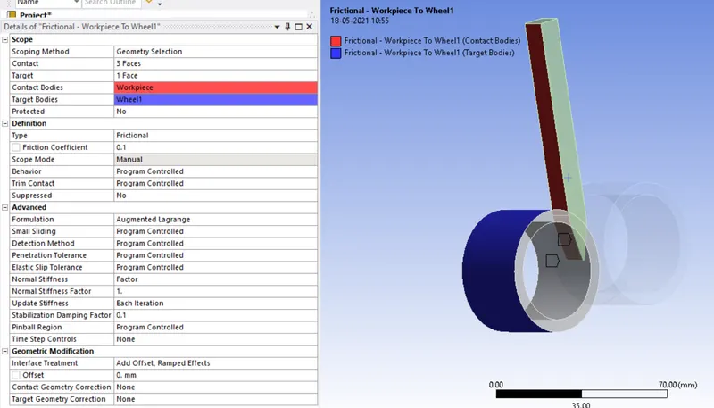
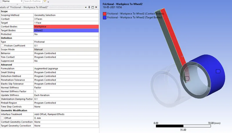
- Under Connections, default contacts are established between the parts. Rename the contacts by definition.
- Flip the contact and target bodies by using the Flip Contact/Target option.
- Then assign required connections in this assignment we will use frictional contact between the components and give cylindrical joints inside the roller.
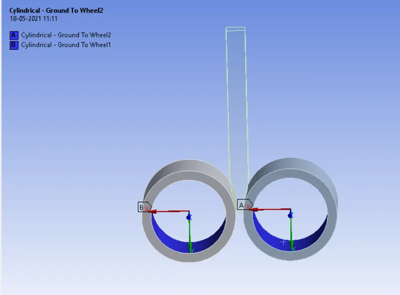
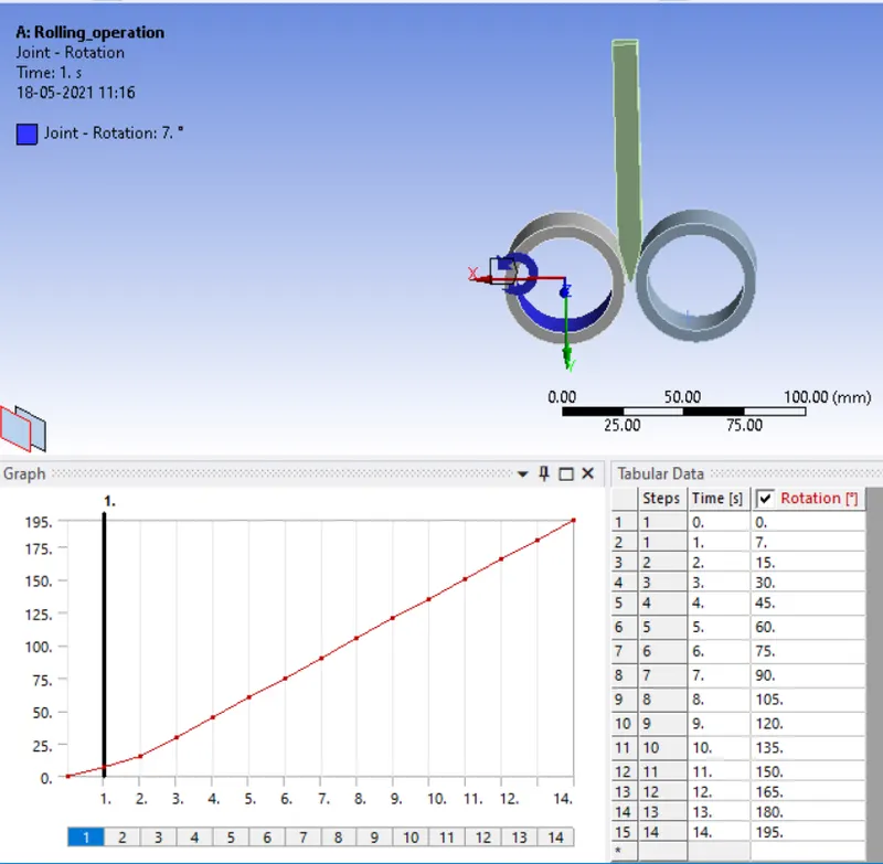
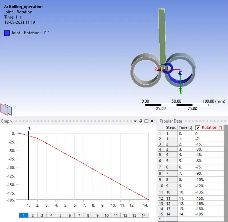
- For joints, the 2 wheels will have rotation along the z-axis so joints are created for the 2 wheels by Connection -> Joint -> Body to ground -> Cylindrical, click on Scope= select inner face of the wheel and also reverse the z-axis by clicking on Coordinate system= Reference coordinate system.
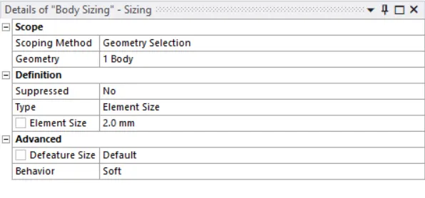
- Select the workpiece that is in contact and apply a mesh sizing feature having a mesh size of 2mm
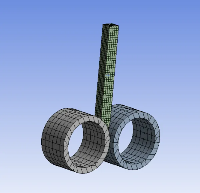
- Then mesh the component with the required mesh size in this assignment we will use
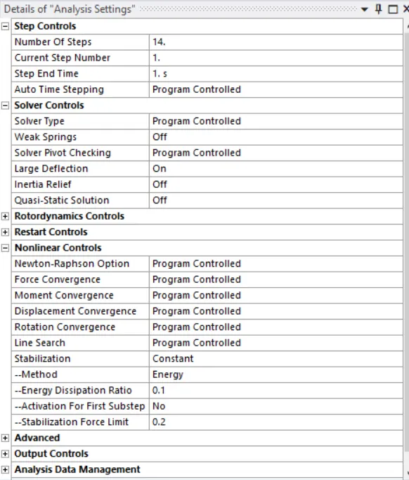
- In the analysis settings, give appropriate parameters to the setup
- Then give the displacement load.
- For the 2 wheels apply the joint load, type= rotation and dof= rotation z and magnitude= tabular such that one wheel rotates clockwise and the other anticlockwise
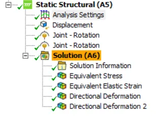
- Provide the required output request for the solution like Equivalent stress for the whole setup, Equivalent Plastic strain for the workpiece, Directional Deformation in the Z-axis for the workpiece, and to prove that the workpiece has displaced by 90mm choose Directional deformation and select the front 2 surfaces of the workpiece.
RESULT:-
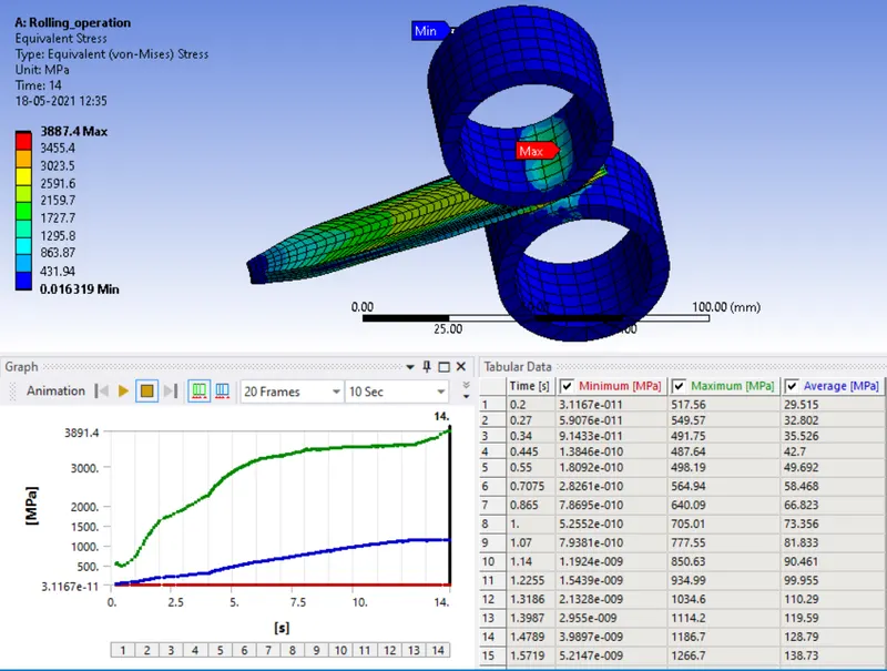
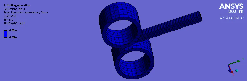
Equivalent Stress On The Whole Setup
-
After the simulation, the equivalent stress on the whole setup is generated from which the workpiece experiences the maximum stress of about 3887.4MPa and wheel 1 experiences minimum stress of about 1.6319e-002 MPa
Equivalent Plastic Strain For The Workpiece
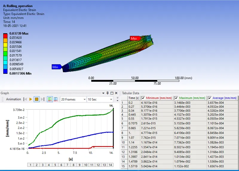
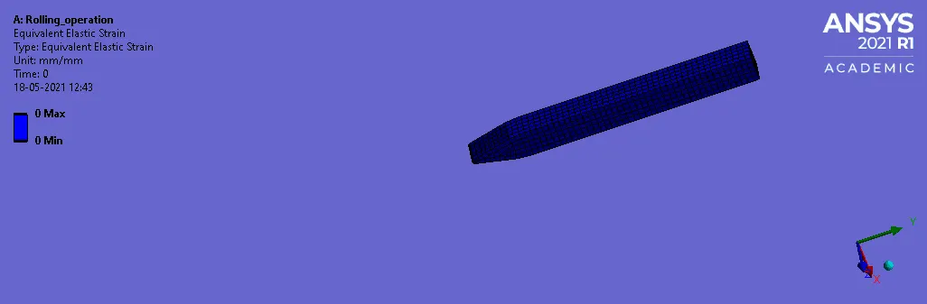
- The equivalent plastic strain on the workpiece shows that the tip of the workpiece experiences the least strain which is about 1.7306e-003 mm/mm and the strain at the end of the workpiece is maximum which is about 3.739e-002 mm/mm
Directional Deformation in the Z-axis for the workpiece
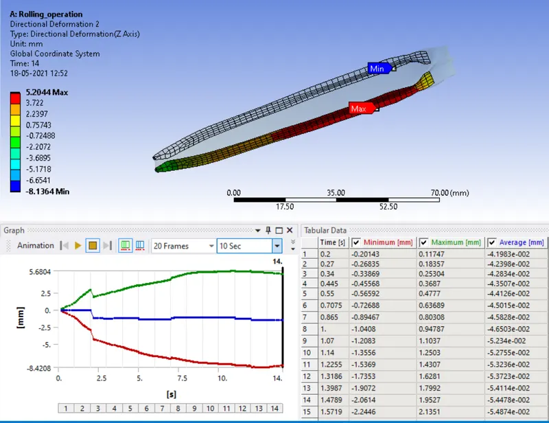
- After the rolling operation, the workpiece thickness is increased along the Z-axis the maximum deformation is about 5.2044 mm
The workpiece has displaced by 90mm:
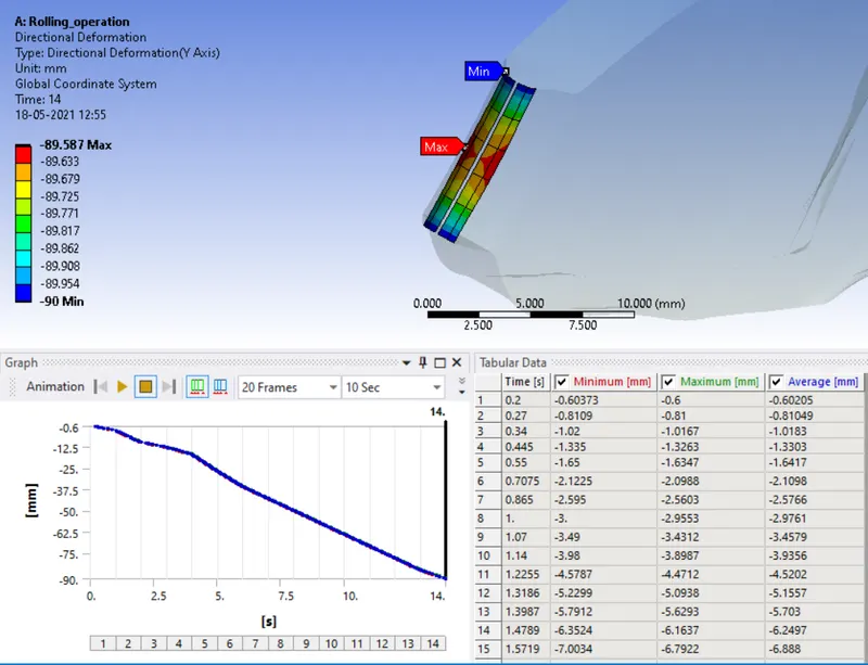
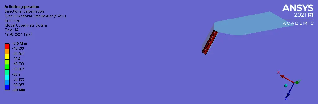
- From the above directional deformation simulation and the graph it can be observed that the workpiece has displaced by near to 90mm the maximum displacement observed is -89.587 mm along the Y-axis.
CONCLUSION:-
So by completing the analysis of the rolling operation of the workpiece of copper alloy non-linear it can be observed that the maximum equivalent stress experienced by it is about 3887.4MPa while the thickness along Z-axis is increased maximum of 5.2044 mm as the workpiece is displaced along the y-axis to the maximum displacement of -89.587 mm.