Week 4- Rolling operation
AIM :
To Performing a Simulation of Rolling Operation by using Copper Material. All Should be done in ANSYS.
OBJECTIVES :
Adding and Assigning a appropriate material as per requirement.
Apply a connection between the contact surface.
Discritization of a model.
Applying a Boundary Conditions.
Calculate a Equivalent Stress, Equivalent Plastic Strain, Direction Deformation on Z axis & Y axis.
INTRODUCTION :
In Metal working, a rolling is a metal forming process in which metal stock is passed through between one or more pairs of rolls to reduce the thickness, to make the thickness uniform and impart a desired mechanical property. The Concept is similar to the rolling of dough. Rolling is classified according to the temperature of the metal rolled. If the temperature of the metal is above its recrystallization temperature, then the process is known as hot rolling. If the temperature of the metal is below its recrystallization temperature, that process is called Cold Rolling.
A Important concept of this rolling process is, volume of the material is same before and after.
PROCEDURE FOR ATTAINING THE OBJECTIVES :
I) CAD MODEL :
A Components are given from design team. We have to importing the given model through the Geometry Selection option. Inorder to check the given model whether it's proper or not. A Components are looks like as shown in the below and it have consists of two roller and work piece as a material of Copper.
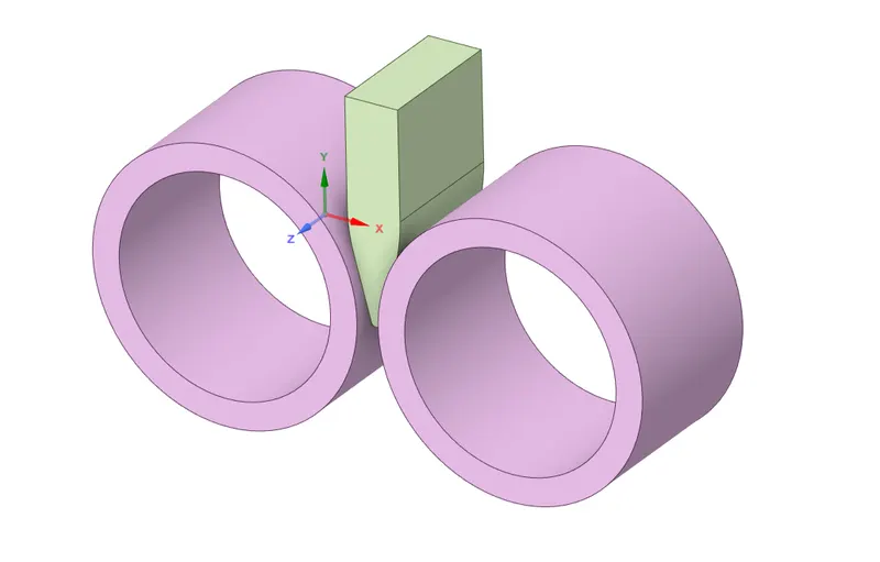
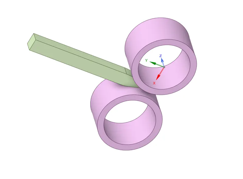
We have to change the workpiece dimensions according to the requirement. We have to increase the length of the work piece upto 80 mm and decrease the width of the work piece upto 8 mm on both sides.
Once, a model has been changed based on the requirement, it will looks like as shown in the below image.
II) Material Adding and Assigning :
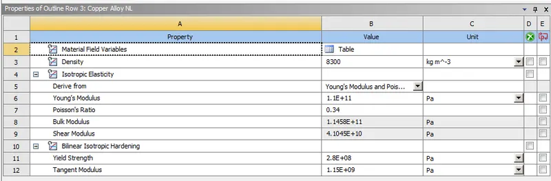
We have to use two different materials in this case, a Copper Alloy material for Work piece and a Structural Steel material for Roller.
III) Connections :
Contacts :
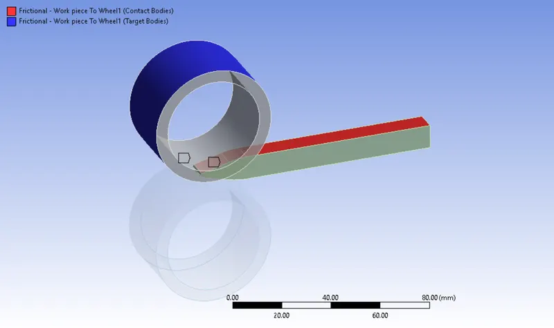
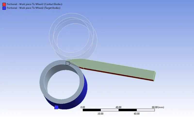
Frictional Contact between Roller 1 to Work piece :
Select the Work piece top face as a contact Bodies and select the roller outer face as a Target Bodies.
Keep Contact type is Frictional and coefficient of friction is 0.2.
Keep "Augmented Lagrange" for Formulation.
Keep "Factor" for Normal Stiffness and the corresponding value is 0.1.
Keep "Each Iteration" for Update Stiffness.
Keep "Add Offset, Ramped Effects" for Interface Treatment.
Frictional Contact between Roller 2 to Work piece :
Select the Work piece top face as a contact Bodies and select the roller outer face as a Target Bodies.
Similarly, keep all those as same as what we did in previous contact.
Joints :
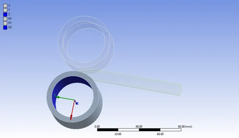
Create a New Joint connection, followingly select the inner face of the roller 1 and then Make sure keep "Body to Ground" as a connection type.
Select "Cylindrical" as a type of joint, it will automatically constraint the motion of X & Y linear and Rotational translation.
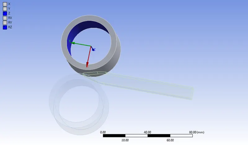
Similarly, we will do for a Roller 2.
IV) Meshing :
Basically, To divide the entire model into infinitesimal control volume, that frame work is called Meshing. This process is called Discritization. This FEM is widely used for solving partial differential equation in different physical field such as Structural problem, Heat transfer problem, Fluid flow problem, Electro magnetic Analysis & Acoustics Analysis.
Body Sizing :
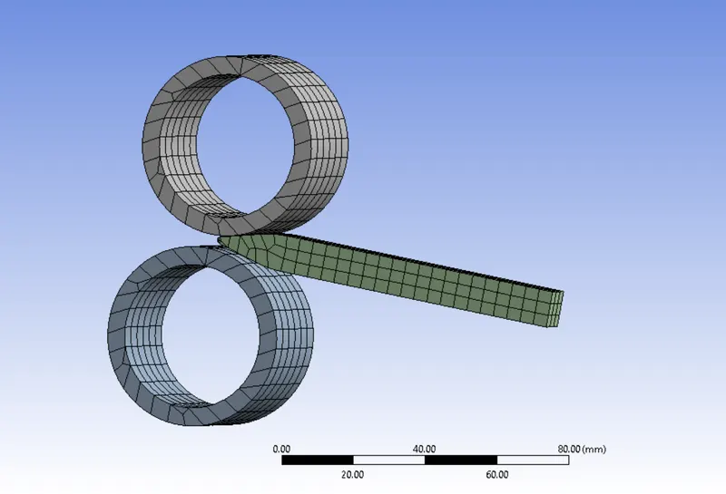
Select the workpiece and proceed the meshing process with element size of 4 mm.
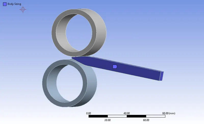
Number of Nodes = 4137
Number of Elements = 621
A pair of Roller and Work piece are meshed with mixed volumetric elements.
After done the meshing, it will looks like as shown in the below image.
V) Analysis Settings :
In this case, we have to calculate the rolling operation by 14 number of steps.
Keep "Program Controlled" for Auto Time Stepping.
Keep "Program Controlled" for Solver Type.
Keep "ON" for Large Deflection.
Enable the "Constant" for Stabilization and provide the Energy dissipation ratio is 0.1
Boundary Condition :
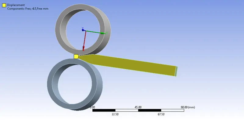
Displacement :
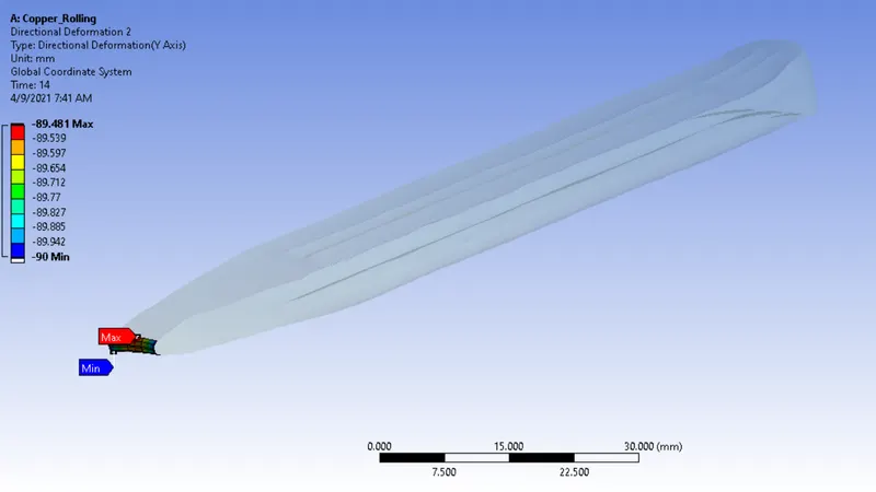
Select the faces on both sides and provide the displacement values on along Negative Y direction from 0 to 90 mm. Keep "Free" as X & Z direction.
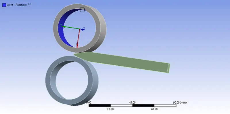
Rotational Joint :
Create a Rotational Joint for roller 1, then provide a angular displacement from 0 degree to 195 degree on Clockwise direction with interval of 14 Number of Time step.
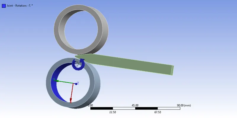
Rotational Joint :
Once again create a Rotational Joint for roller 2, then provide a angular displacement from 0 degree to 195 degree on CounterClockwise direction with interval of 14 Number of Time step.
RESULTS :
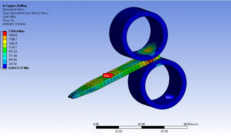
Equivalent Stress :
A maximum stress is developed on a work piece at where point of contact between roller and Work piece.
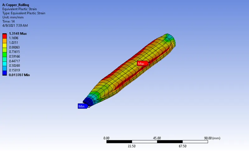
Equivalent Plastic Strain on the Work piece :
A Maximum Plastic Strain is developed on side faces of the work piece. A plastic deformation is a permanent deformation.
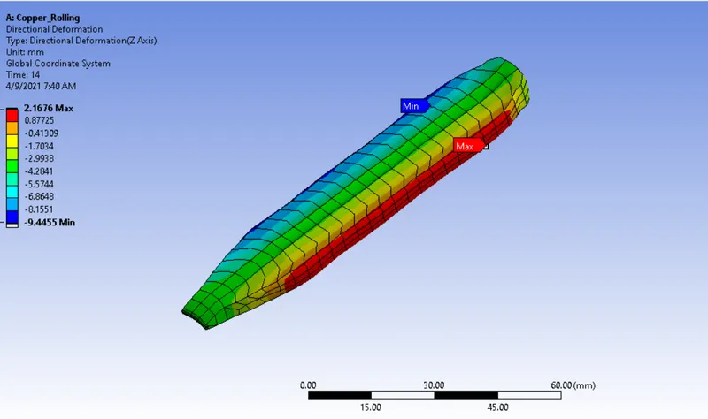
Directional Deformation on Z axis :
Directional Deformation on Y axis :
CONCLUSION :
Based on the Equivalent Stress from the simulation, we can calculate the require load to change the shape of the work piece.
A Directional Deformation on Z axis is a same as we provide the values in numerically.