Week 4- Rolling operation
ROLLING OPERATION ON A COPPER WORKPIECE
Objective: -
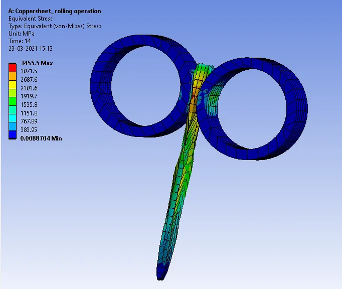
- Equivalent stress for the whole setup
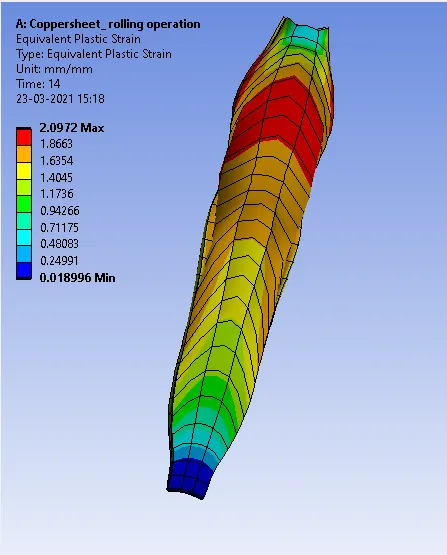
- Equivalent Plastic strain for the workpiece
- Directional Deformation in the Z axis for the workpiece
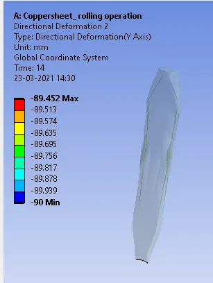
- Ensure that the edge of the workpiece is displaced by 90mm.
Procedure: -
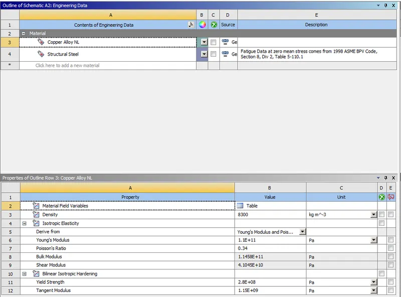
- Drag and drop the static structural analysis system and load the copper alloy NL material from the non linear material library.The workpiece is made up of copper alloy NL and the two wheels are made up of structural steel.
Geometry: -
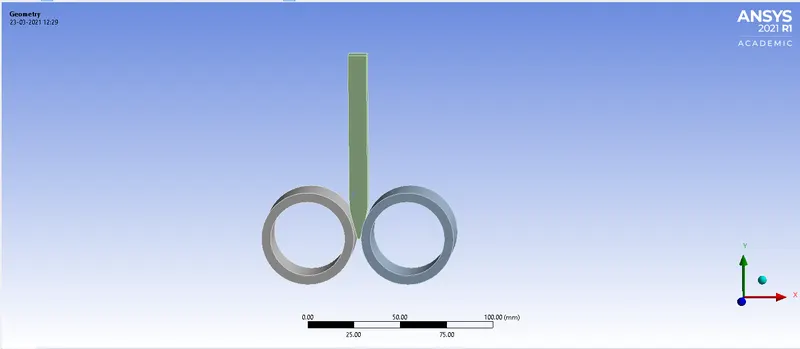
- Open spaceclaim and increase the length of the workpiece by 60mm and decrease its size on both sides by 8mm.
Connections: -
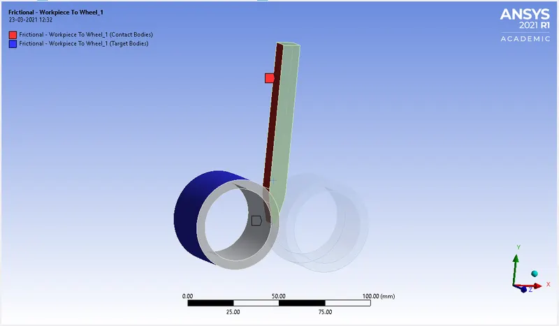
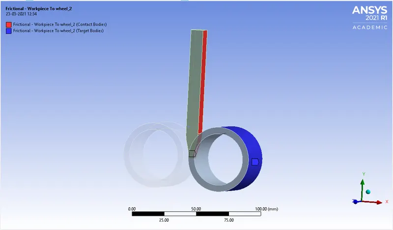
- Frictional contacts are provided between the workpiece and the wheel with a frictional coefficient of 0.2.
- Three faces of the workpiece are selected as the contact body and outer face of the wheel is provided as the target body.
- Contact formulation is set to augumented lagrange.
Joints: -
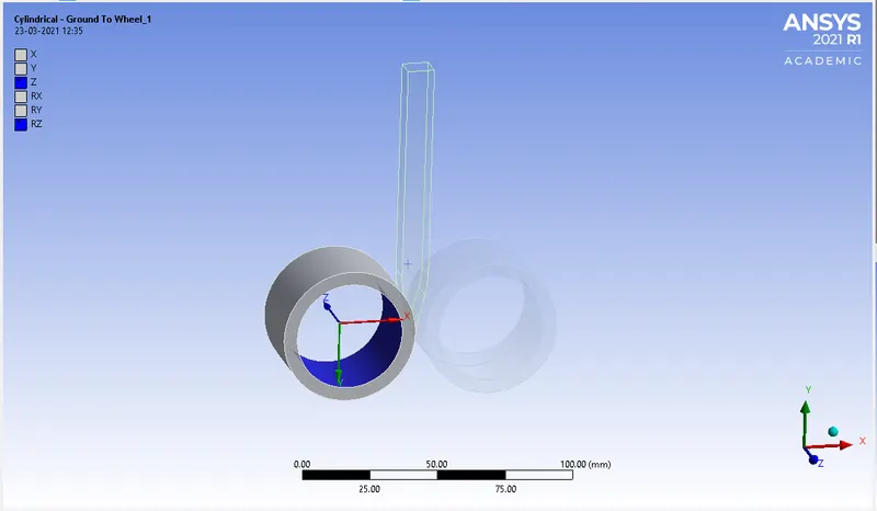
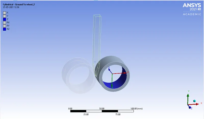
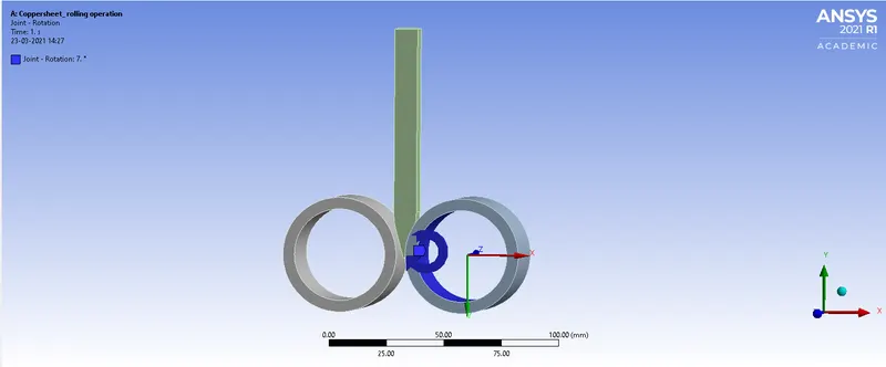
- Cylindrical joints are provided to both of the wheels. Change the reference coordinate system for both of the wheels.
Meshing: -
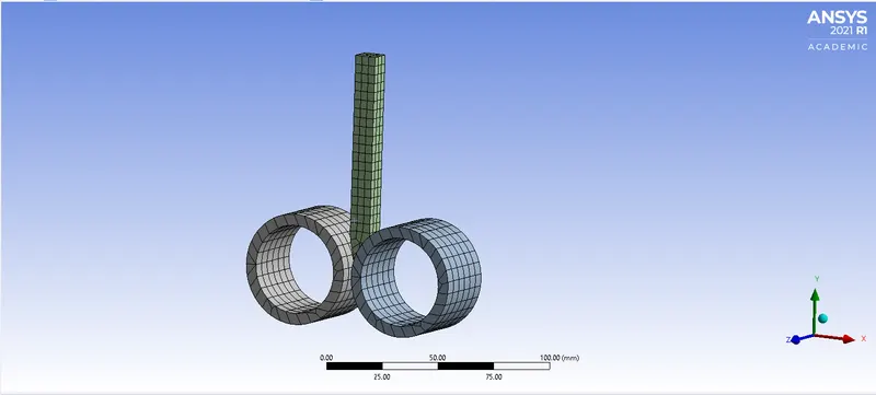
- A mesh sizing of 4mm is provided to the workpiece to get an accurate result.
Boundary conditions: -
- A displacement load of 90mm is provided to the workpiece in negative y-direction.
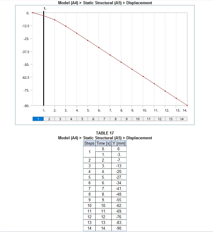
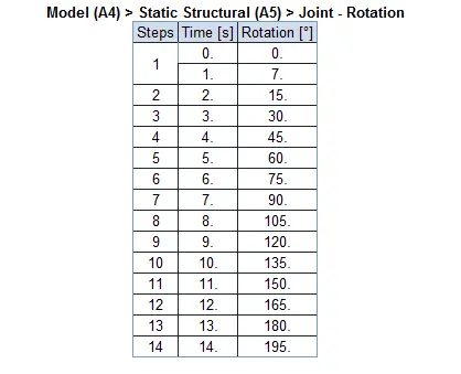
- The below table represents the rotation of the wheel in 14 steps. The second wheel has the same degrees of rotation with a negative magnitude.
Results: -
- Equivalent stress plot for the rolling operation.
Equivalent plastic strain developed in the workpiece.
CONCLUSION: -
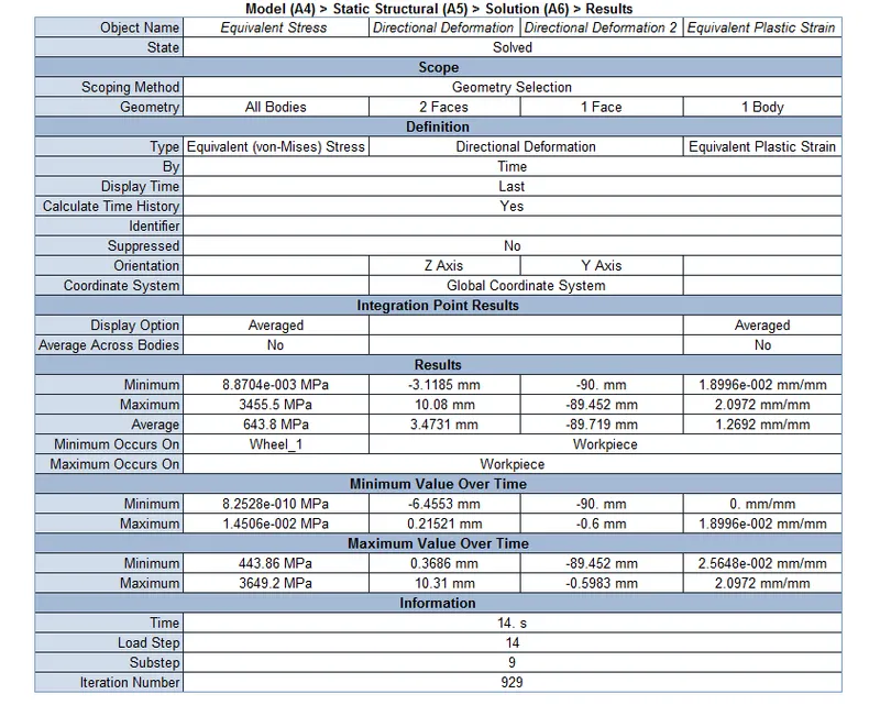
- The workpiece has a directional deformation of 10.31mm along z-axis.
- A directional deformation of 90mm along y-axis is achieved.