Week 4- Rolling operation
ROLLING OPERATION
OBJECTIVE
To perform a rolling operation analysis where a copper specimen is rammed by two rollers which causes excessive deformation on the workpiece and this deformation along with other required parameters like von mises stress and strain has to be extracted from the analysis.
INTRODUCTION
Rolling is a metal forming process where the workpiece is passed through one or more pairs of rolls to reduce the thickness, or to make the thickness uniform, and/or to impart a desired mechanical property like increased hardness.
There are two types of rolling operations performed: If the temperature of the metal is above the recrystallization temperature, then the process is known as hot rolling and if its below its recrystallization temperature, the process is known as cold rolling
PROCEDURE
- Create a new static structural simulation
- Import copper alloy (NL) along with structural steel for the model. The specimen will be modeled using the copper alloy material
- Import the model file and edit it using spaceclaim/design modeler.
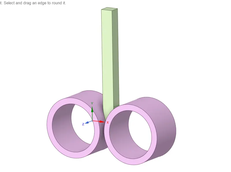
Dimensional changes are made to the model - increasing length by 60mm and decreasing width by 8mm on both sides. Both the operations are performed using the pull command (in case of spaceclaim)
- Then the model module of static structural is again updated.
- Open the model in ansys mechanical module.
Contact region
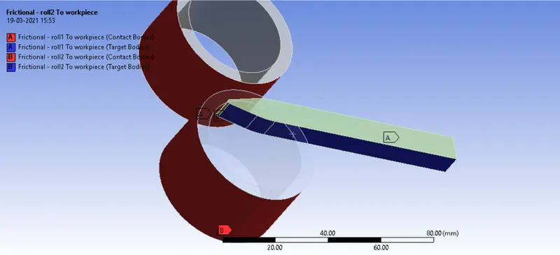
- Two contact sets are defined for the rolls and specimen. Since the model has been modified recheck the contact pairs.
- Add a frictional contact of 0.2 frcitional coeff and set it to ramped.
Joint
- Define two cylindrical joints for the rollers to define its movement. Makes sure the axis of rotation and direction of rotation for both are same
Mesh
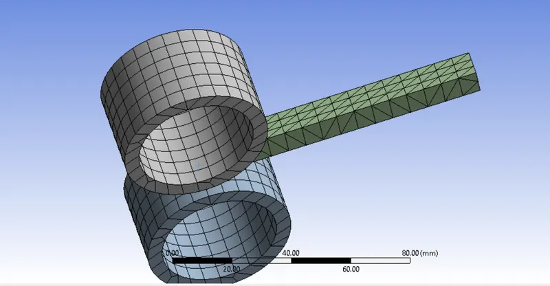
- To refine the mesh of the workpiece at the contact regions, we can either increase the mesh density using sizing option or alternatively we can create a well structured ortho tria mesh on the speciment using face meshing feature
Loading condition
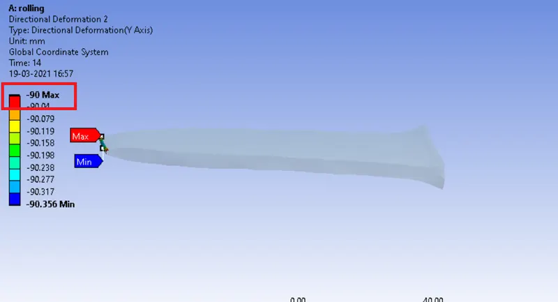
- A deformation aloong the -Y direction is set for the workpiece such that it deforms to a max of 90mm along the Y-axis
- A joint load is added for both the cylindrical joints on both the rollers, which are made to rotate about the Z axis at specified angular displacements.
Analysis settings
- A total of 14 steps were defined with the displacement upto a certain random value at each time step.
- A min and max time step increment/decrement was set to 0.05 and 0.5 respectively
- Large displacement and stability in non-linearity was turned on
RESULTS
The following results were obtained
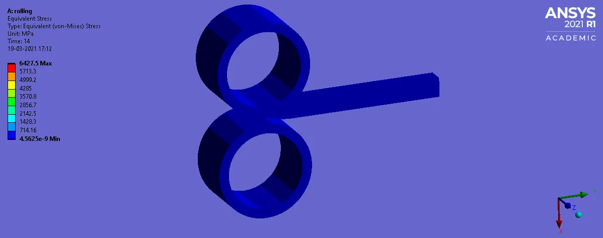
Equivalent stress
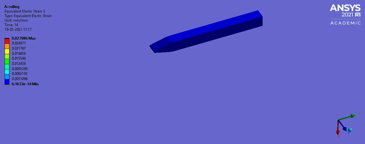
Equivalent strain (workpiece)
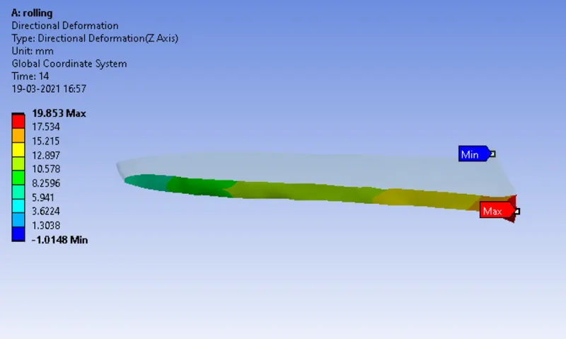
Directional displacement (Z)
Max displacement of the specimen (Y)
CONCLUSION:
Hence the rolling operation of two rollers deforming a copper specimen is simulated using Ansys and the required field variables like equivalent stress, strain and the directional deformation about a certain axis were extracted and ploted above.