Week 4- Rolling operation
AIM:
To perform the Rolling simulation on given workpiece.
PROCEDURE:
- First we will import the geometry and edit it. And after that we will assign the conditions to it.
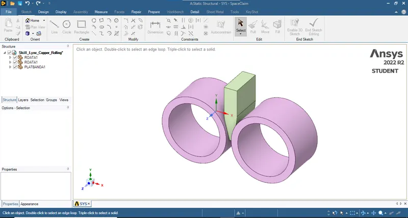
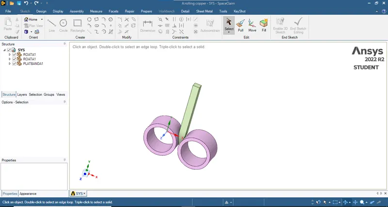
- So this is how the component looks like. And after this We will use pull operation to edit the component. So the final component is shown below:
- Now after that we will edit the mechanical module.
- Now we will assign the copper material to workpiece.
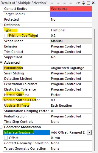
- After that we will assign the contacts to, make sure that the contact body is workpiece and the target body is roller.
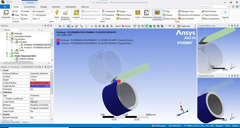
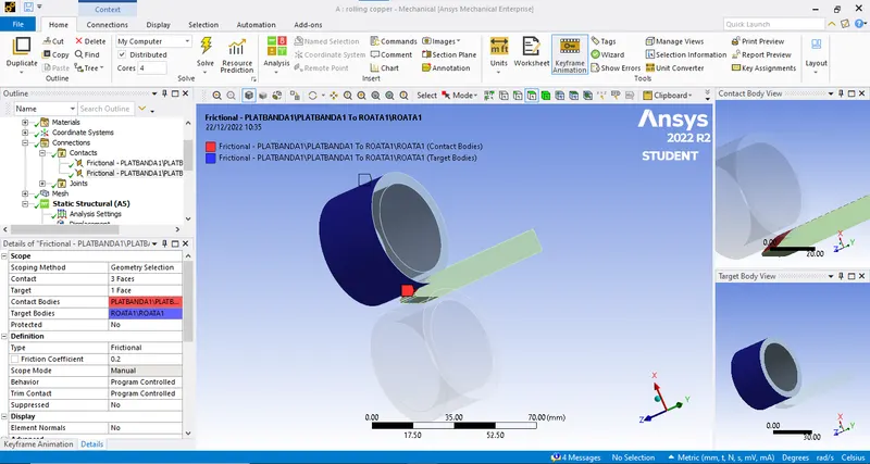
- Aftrer this chnage the type of connection as frictional and change the setting as given below:
- Now after that we will create the joints for the roller. So here we are using cylindrical joints as shown below:
- Make sure that Y axis is in downward direction.
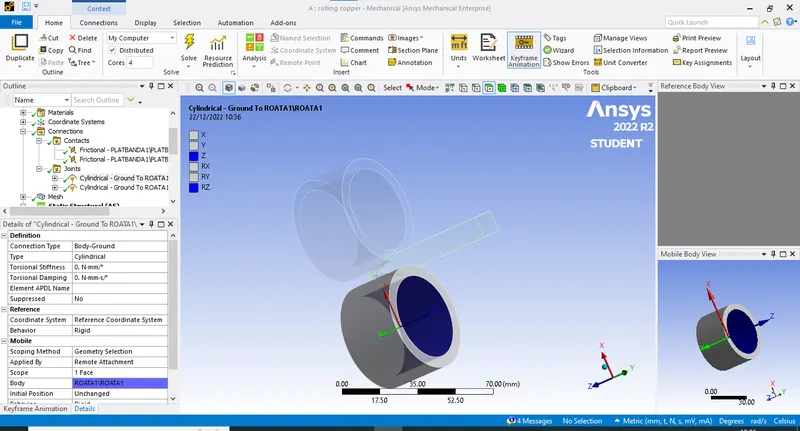
- Do the same with other roller too.
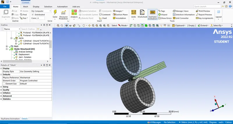
- Now after this we will mesh the component with mesh size as 5mm and by using sizing we will chnage the mesh size of the workpiece as 2mm. As shown:
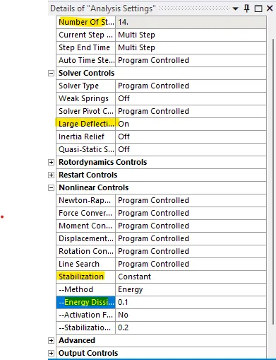
- Now after this we will change the analysis setting as shown:
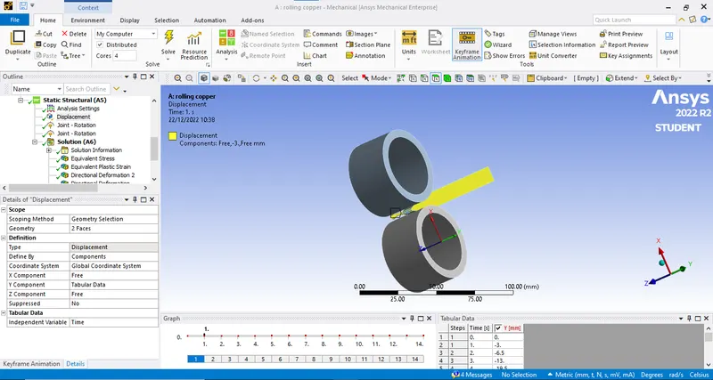
- Now first we will assign the displacement for the workpiece shown below:
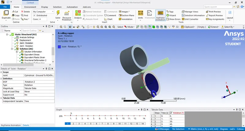
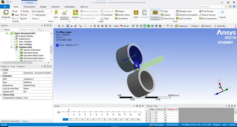
- After this rotation for the roller. Make sure the rotation for one roller is positive direction and for other is in negative direction as shown:
- Now we will add the results we required and then solve the simulation.
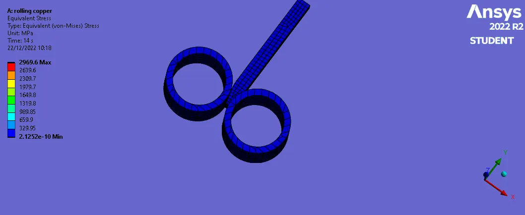
Equivalent stress for the whole setup : 2969.6 MPa
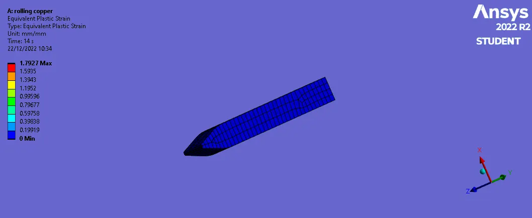
Equivalent Plastic strain for the workpiece: 1.7927
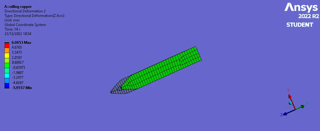
Directional Deformation in the Z axis for the workpiece: 6.0053 mm
Prove that the workpiece has displaced by 90mm:
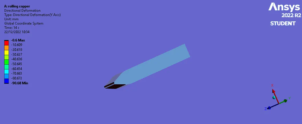
- Here you can see the wokpiece is displaced by 90.68 mm which is near to 90mm.
CONCLUSION:
- All the results are plotted as per the requirement.
- The displacement of the workpiece is 90 mm is also proved.
- The maximum stress on the workpiece is 2969.6 MPa