Week 4- Rolling operation
STIMULATION OF COPPER ROLLING OPERATION
OBJECTIVES:-
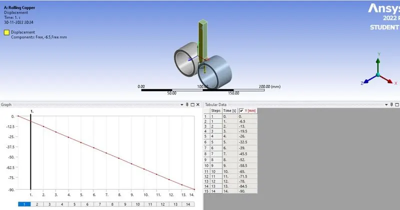
In this challenge, we have to simulate the rolling operation on a workpiece made of copper, by Increase the length of the workpiece by 60mm and decrease its size on both sides by 8mm. Run the simulation for 14 steps of random values for the displacement and ensure that the edge of the workpiece is displaced by 90mm.
PROCEDURE
Select Material :-
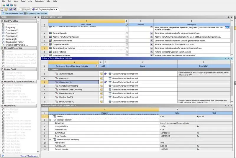
- First, we have to input the engineering materials with required properties or else by creating with required properties FORM engineering data
- Select the Non linear Copper material from engineering data
- Import Geometry :-
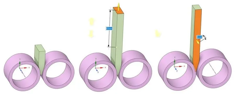
a. Imported model. b. Length increased to 60 mm. c. Width decreased on both side by 8 mm.
-
3D model of copper rolling operation.
The given 3D model of copper rolling assembly is imported into SpaceClaim. The length of the workpiece is increased to 60 mm and the width is decreased on both sides by 8 mm.
- Set Connection Details :-
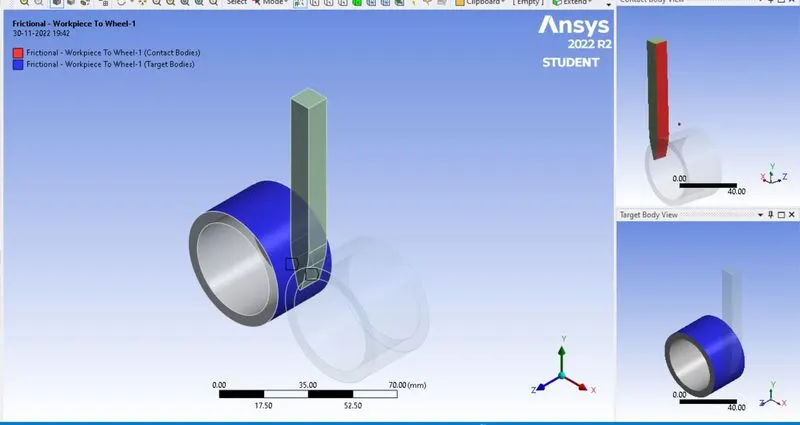
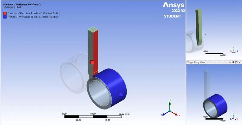
Contact between, (a) Workpiece (contact body) and wheel 1 (target body), (b) Workpiece (contact body) and wheel 2 (target body) are assigned as frictional contact with coefficient of friction = 0.2. The formulation type of contact is set as Augmented Lagrange and normal stiffness value is inputted as 0.1 factor with update stiffness set to as ‘each iteration’.
Connection No. 1 :- Contact between workpiece and wheel 1.
Connection No. 2 :- Contact between workpiece and wheel 2.
Joint Details :-
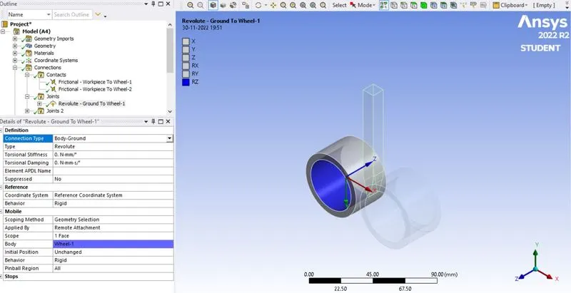
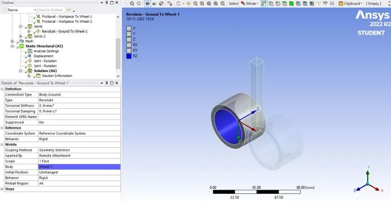
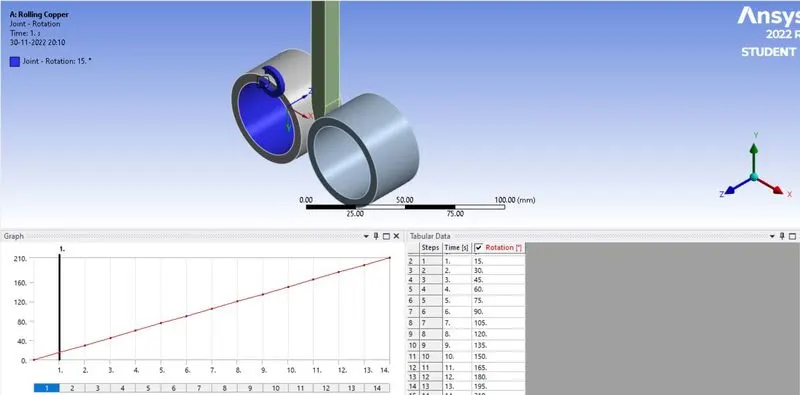
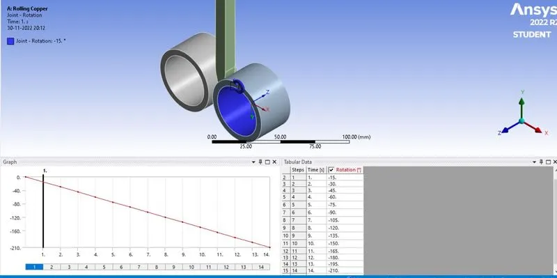
The revolute type of joint is selected for both wheels with connection type being body-ground, since only rotation is specified to the wheels.
Joint No.-1
Joint :- 2
Meshing :-
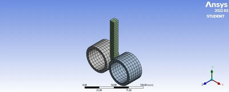
Meshing details of copper rolling model.
The element size of workpiece is set as 4 mm using body sizing option. The total number of nodes and elements generated are 4025 and 603 respectively.
Note: The academic version of software has the problem size limit of 128k nodes or elements.
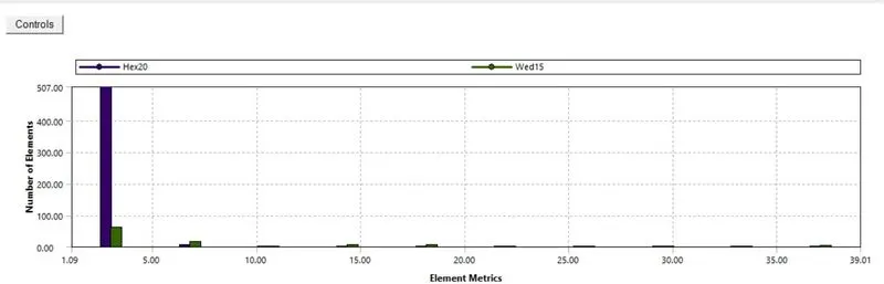
Check for Mesh Matrics(Aspect Ratio) :-
Set Boundary Conditions :-
Analysis settings:-
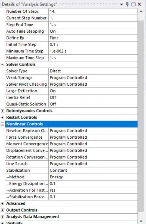
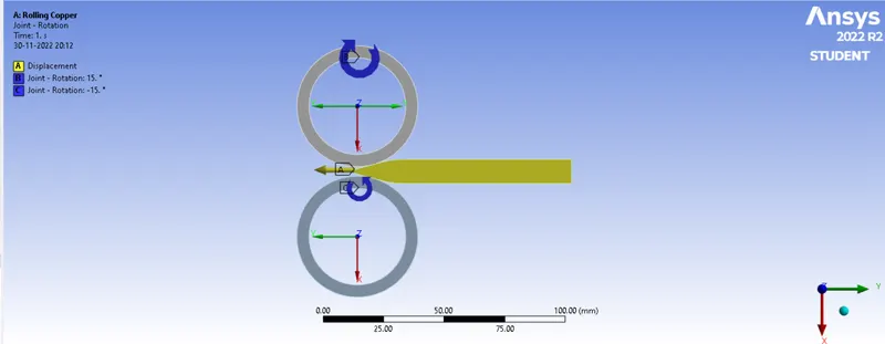
In the analysis settings the number of steps considered is 14. In solver controls, large deflection is set to ‘On’. Under the nonlinear controls, the stabilization is set as constant with energy dissipation ratio being 0.1.
Boundary condition for copper rolling operation:-
i)Apply Displacement :-
ii) Apply rotation to Wheel-1
iii) Apply rotation to Wheel-2
Results :-
i) Equivalent stress for the whole setup :-
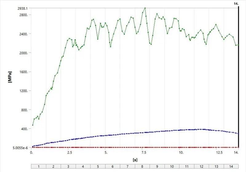
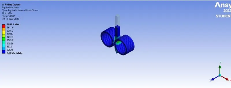
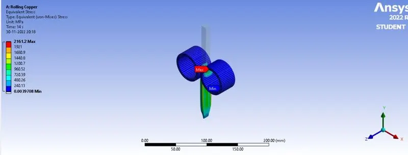
The maximum v-m stress developed in the whole setup of rolling operation is 2938.1 MPa . The workpiece is plastically deformed by reducing its thickness and increasing its width.
Equivalent Plastic strain for the workpiece:
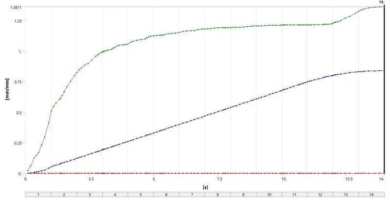
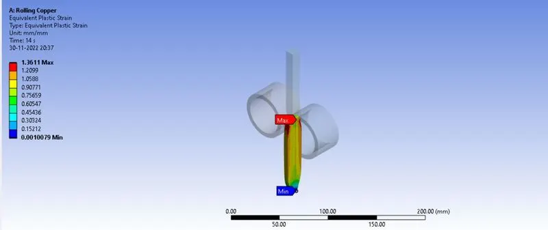
The maximum strain developed in the workpiece is 1.3611 mm/mm
Directional Deformation in the Z axis for the workpiece:
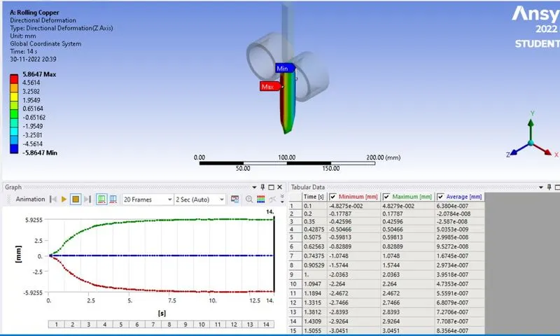
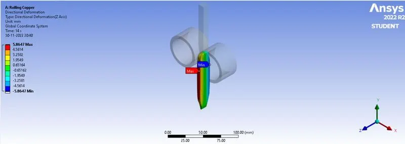
It is observed that the workpiece has deformed 5.9255 mm along positive and negative direction of Z-axis.
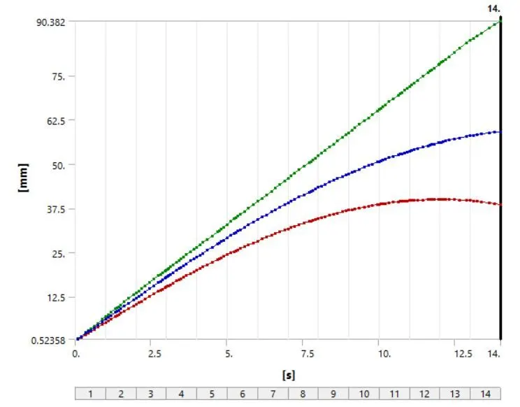
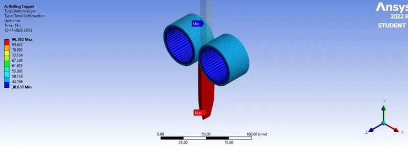
3.4 Directional Deformation in the Y-axis for the workpiece to show that it has displaced by 90mm:
CONCLUSION
- The given model was opened in spaceclaim and the length of workpiece was increased by 60 mm and its width was decreased by 8 mm on both sides.
- The simulation of the rolling operation on a workpiece made of copper was made to run for 14 steps successfully.
- The Equivalent stress for the whole setup is 2938.1 MPa .
- The Equivalent Plastic strain for the workpiece is 1.3611 mm/mm
- The Directional Deformation in the Z-axis for the workpiece is 5.9255 mm
- The Directional Deformation in the Y-axis for the edge of workpiece is 90.013 mm. Hence, it is proved that the workpiece has displaced by 90mm.