Week 4: Project - Transient simulation of flow over a throttle body
AIM
* To run a transient simulation on a throttle body.
* To show meshed surface, velocity and pressure contour.
* To show plots for velocity, pressure and mass flow rate.
* To show animation of fluid flow through throttle body.
INTRODUCTION
Flow of fluid through a throttle can be related to flow through a pipe only difference being that there will be a throttle which will control the flow of fluid through. Since the rotation of throttle is a time dependent process a transient state simulation is run. When throttle rotates the flow pattern around the throttle becomes chaotic. Simulation is run and the changes around the throttle is observed.
SIMULATIONS
Geometry:
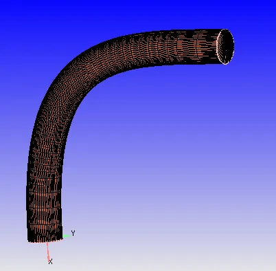
The throttle body used for this simulation is a 'L' shaped elbow like structure inside this elbow the throttle valve is present which is intended to control the flow. Below is the snip of the geometry,
hiding some of the surface triangles makes the throttle valve visible, snip of the same is provided below
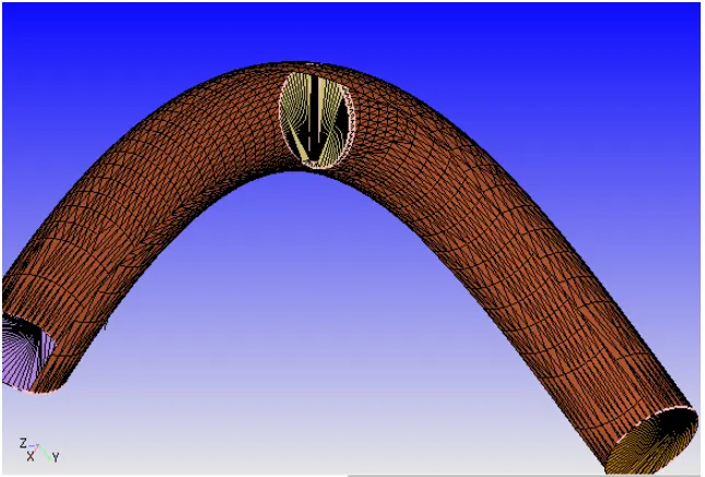
In practice both ends of the throttle will be attached to the walls of the elbow pipe through a rotating axis, the point where the rotation axis is attached to the elbow wall is made leak proof with help of 'O' rings. But in this geometry the throttle valve is not attached to the elbow wall so that intersection errors could be avoided.
Case setup:
* Geometry is first opened in converge and a diagnosis is run to check wether there are any surface errors. A snip of the same is shown below,
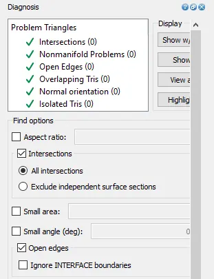
* From the above output it is clear that there are no surface errors and hence we can proceed further in setting up the case.
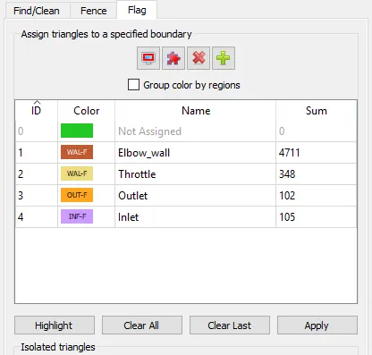
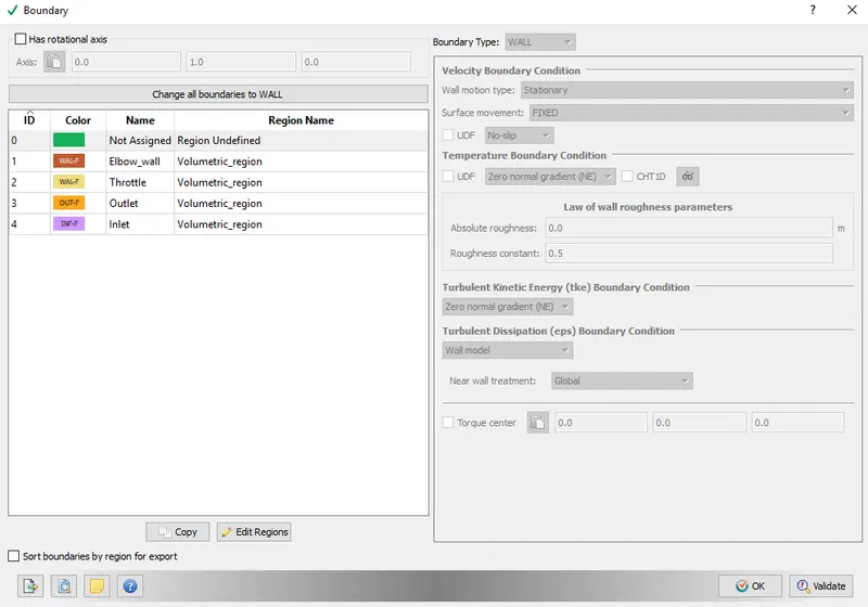
* Boundary's are flagged, for this geometry 4 boundary's are created, inlet, outlet, elbow_wall, throttle. A snip of all flagged boundary's along with the boundary id is provided below,
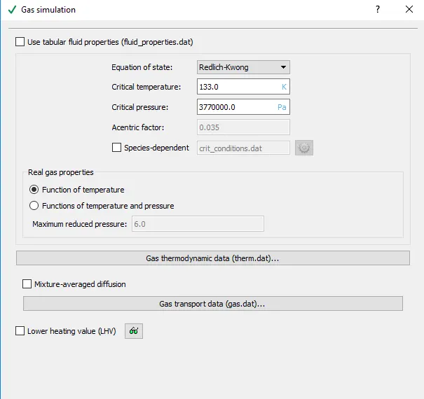
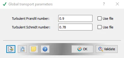
* Gas simulation and global transport properties local controls are left default. Snip of the same is provided below.
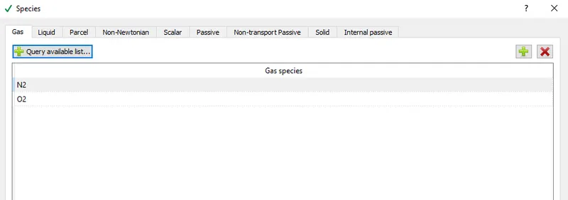
* Gas is the fluid set and `O_2, N_2` are the species set.
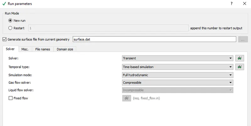
* Under run parameters transient, full hydrodynamic simulation is set and gas flow solver is set compressible.
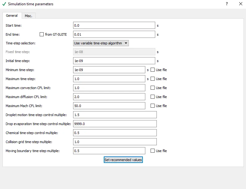
* Under simulation time parameters start time is set at 0 sec and end time is set at 0.01 sec. Following is the end time calculation's,
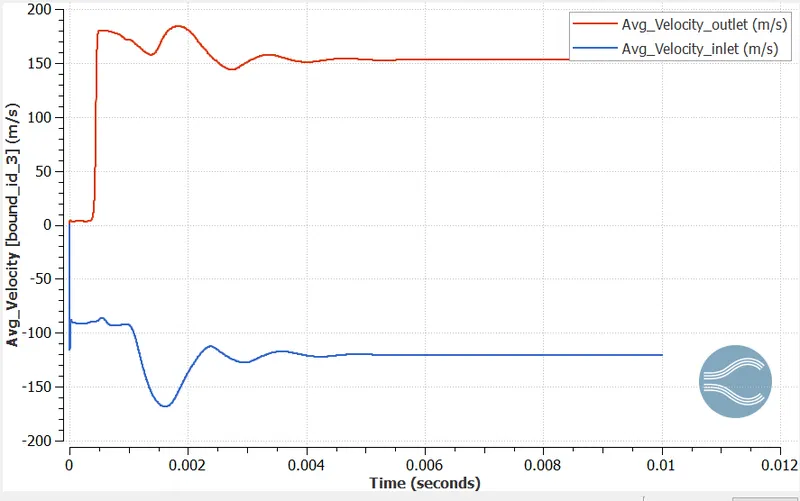
from the steady state analysis of flow through a throttle body we have the final velocity above 200 m/s.
so we have velocity, V = d/t.
d = length of the pipe = 0.20 m
therefor t = 0.2/200 = 0.001 sec, so it takes 0.001 sec for one pass of the fluid through the throttle body
suppose if we want a total of 10 passes through throttle body, so end time = 0.001*10 = 0.01 sec.
* Initial time step and minimum time step is set at 1e-09 and max time step is set at 1.
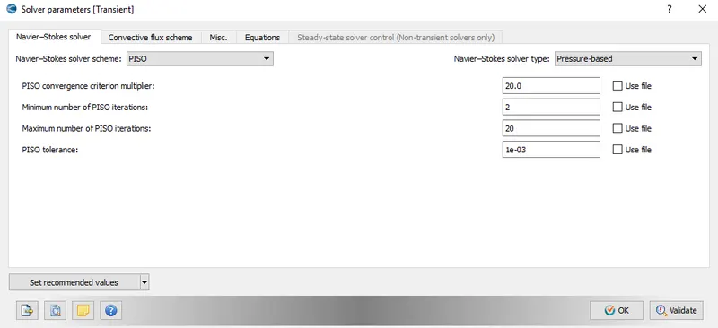
* A pressure based solver is set.
* Next is setting up the boundary condition for the simulation,
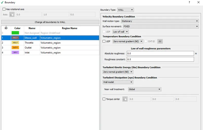
1. Elbow_wall - boundary type is set as wall, with stationary wall motion and surface movement fixed.
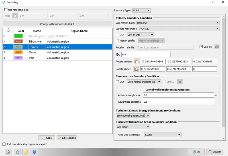
2. Throttle - For this boundary type is set wall, wall motion type is set rotating and surface movement is set moving. Since this is a transient simulation in which we are simulating the flow by rotating the throttle, it is necessary that we define the throttle motion. To define the motion of throttle valve we can either import a file that defines the motion or we can configure the profile of the movement, in this the later is used to set the motion.
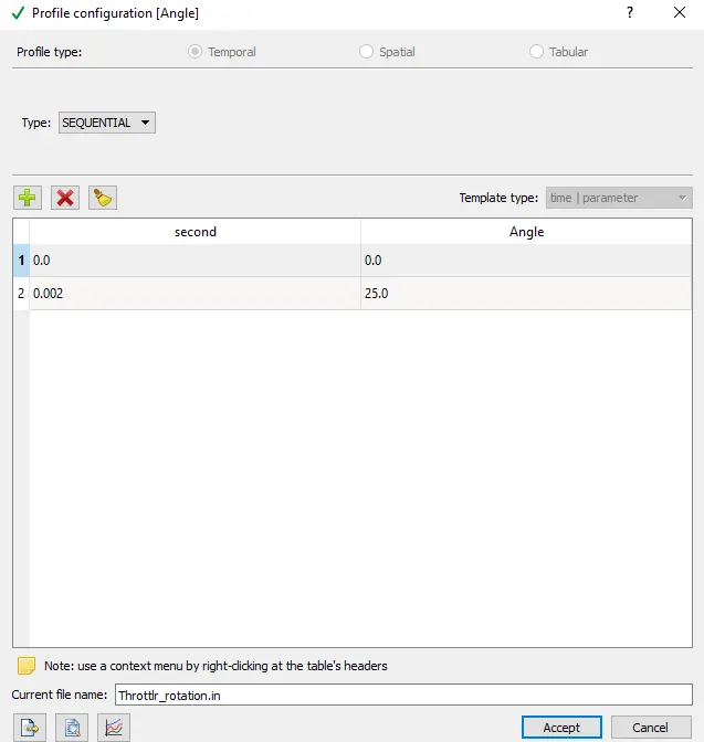
above snip shows the profile configuration window, at start time (at 0 second) throttle movement is set to 0, and at 0.002 sec throttle rotation is set to 25 degree, i.e as the simulation time reaches 2 millisecond the throttle will rotate by 25 degree. After setting up the profile the file has to be saved with.in extension.
* Also it is necessary that we provide rotation centre and align vector (arc normal). This can be computed using the measure option, so computed values are copy pasted.
Below is the snip showing the same,
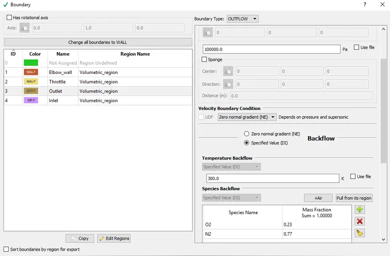
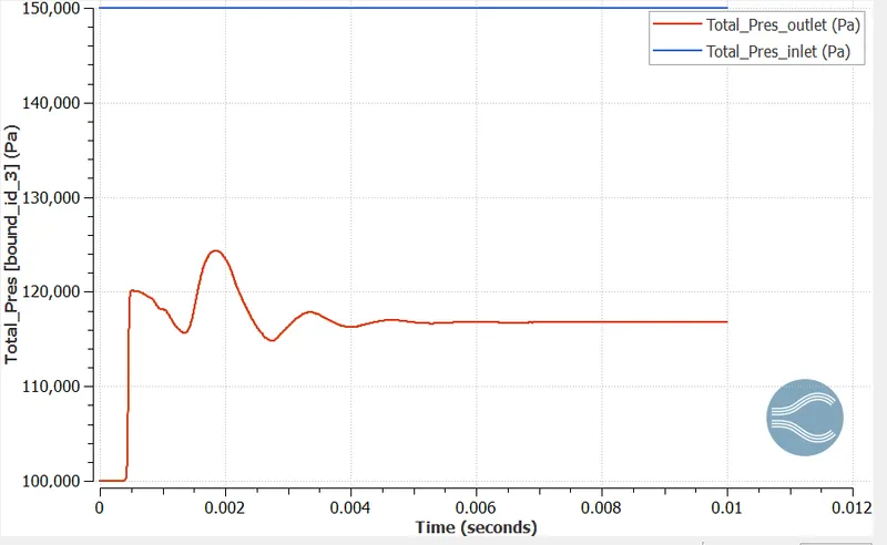
3. Outlet - boundary type is set as outflow and with outlet pressure set at 100000 Pa and temperature set at 300 K. `O_2, N_2` are the species set.
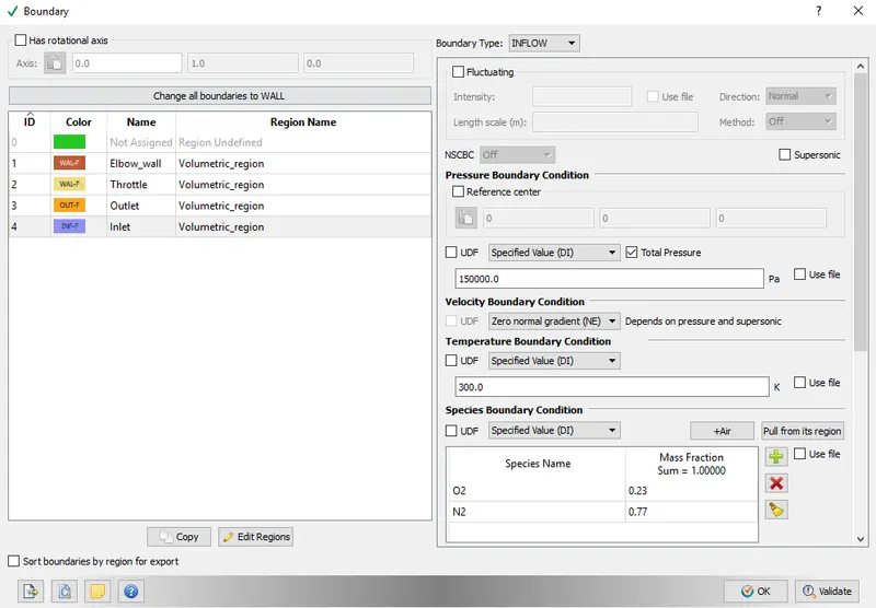
4. Inlet - boundary type is set as inflow, with inlet pressure value of 150000 and temperature of 300 K. `O_2, N_2` are the species set.
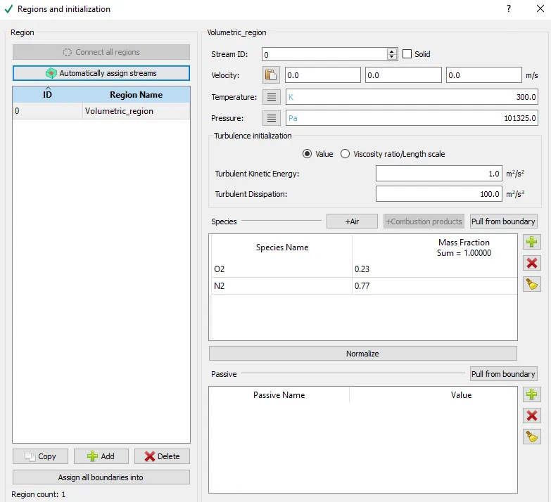
* A volumetric region is initialised with pressure value set at 101325 Pa and temperature set at 300 K, `O_2, N_2` are the species set. All the boundary's defined were assigned to this volumetric_region.
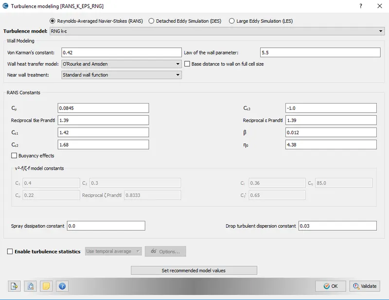
* As far as physical models are concerned, RNG K-ε turbulence model is used.
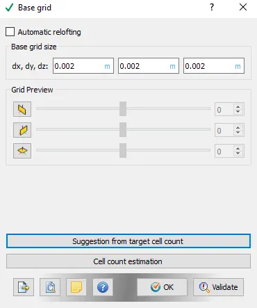
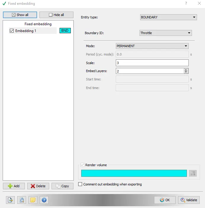
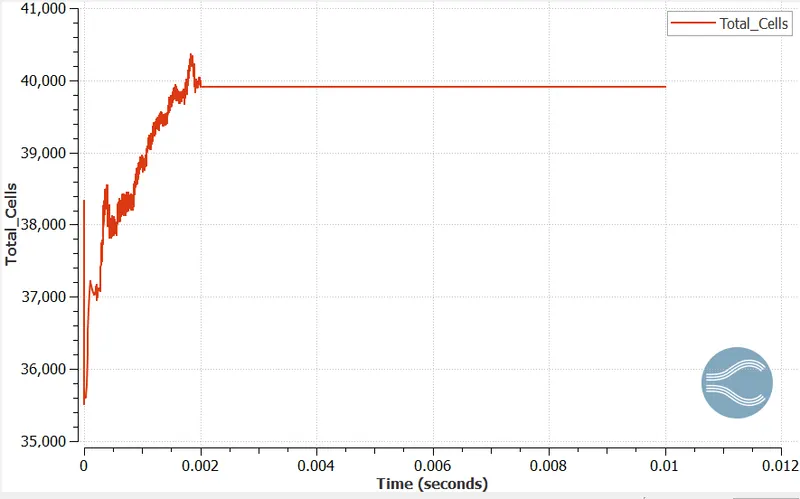
* A base grid size of 0.002 m is used along with fixed embedding at the throttle. Embedding scae of 3 and total embedd layer of 2 is set.
* This completes the case setup to run the transient simulation for flow through throttle body, simulation is run and results are noted.
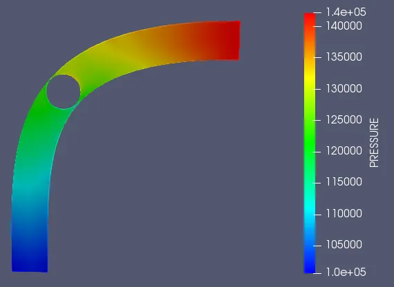
* Pressure contour:
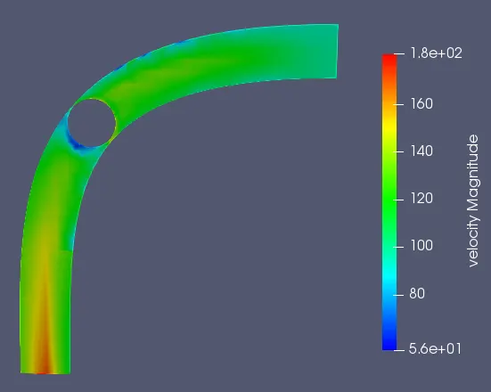
* Velocity contour:
* Pressure plot:
* Velocity plot:
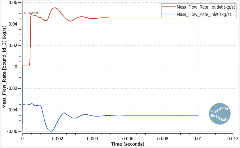
* Mass flow plot:
* Cell count plot:
* Meshed surface:
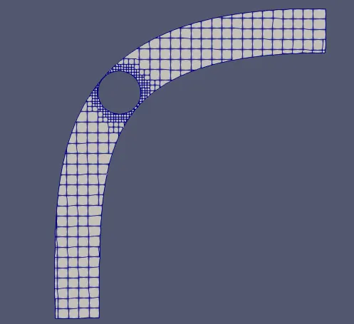
* Embedd layers:

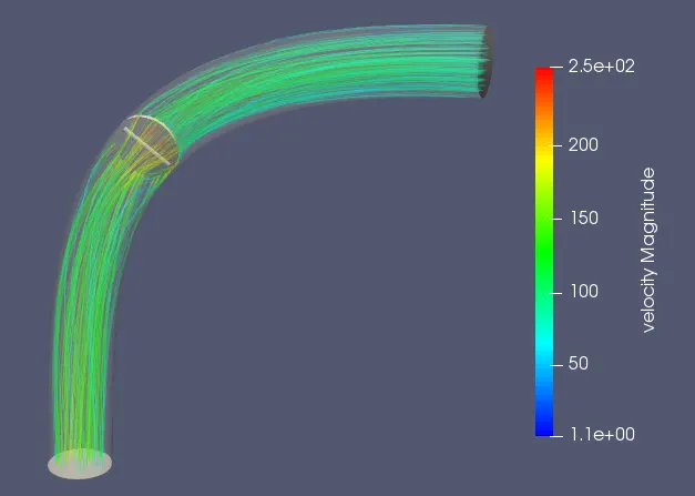
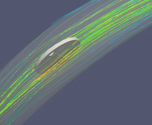
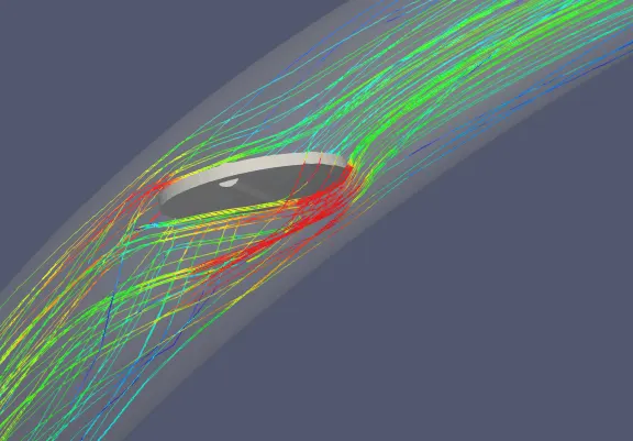
* Velocity streamlines:
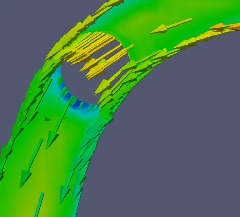
* Glyph:
* Velocity profile animation:
* Observations:
* When throttle valve rotates the flow near the throttle valve becomes chaotic, this is clearly visible from streamlines.
* Flow takes place in adverse pressure gradient but there is no recirculation of the fluid as such near the throttle, rotation of the throttle is the reason for the same.