Transient simulation of flow over a throttle body
Transient State Simulation of Flow Over a Throttle body - Using Converge.
Aim: To setup and simulate the Transient simulation of flow over throttle body.
Objective:
- Setting up Transient state simulation for flow over a throttle body.
- To generate the mesh that gives more accurate results.
- Post processing the obtain results using paraview and show pressure and velocity contour.
Description:
A throttle is the mechanism by which fluid flow is managed by constriction or obstruction.The throttle is a means of controlling an engines power by regulating the amount of fuel or the air entering the engine. The throttle lever acts as a direct mechanical linkage. The butterfly valve of the throttle is operated by means of an arm piece, loaded by spring. This arm is usuall directly linked to the accelerator cable and operates in accordance with the driver, who hits it. Further the pedal is pushed , the wider the throttle valve opens.
Procedure:
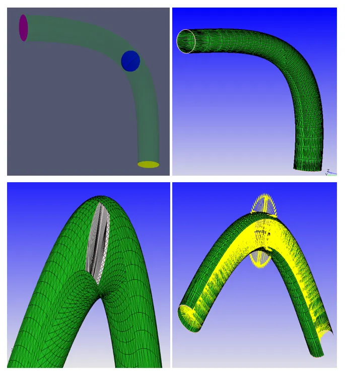
- Initially open Converge Studio and import the the throttle body geometry.
- Next go to Geometry > options > select Surface Normal. After selecting the S.Normal the normals point towards outside, so selec any one arrow that is point outwards and clik on them. Then the normals change their direction to inwards.
- After setting the geometry, next important thing is to diagnosis the geometry for errors/problems. For this go to Right Bottom side, select Diagnosis > click on All intersections > click Find. On top we can check for problems in Problem Triangles.
- Now if there are no errors found then the geometry is correct.
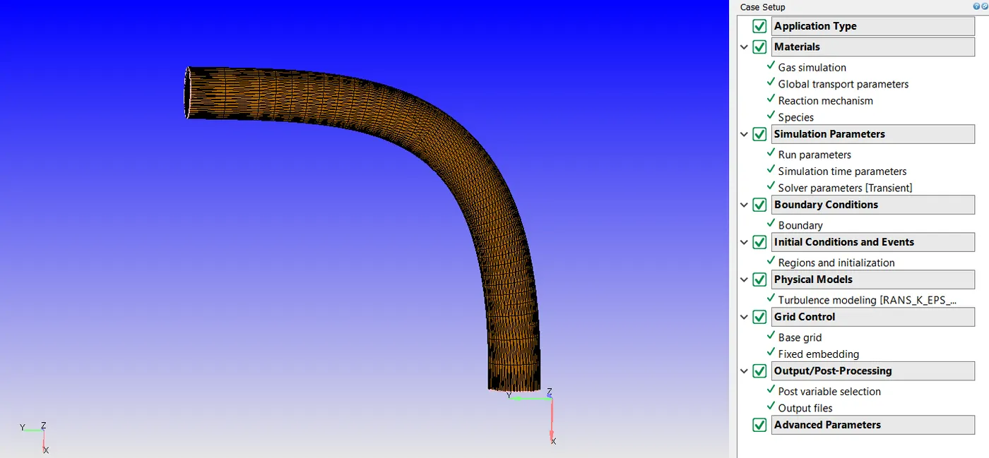
- To we should do Case Setup. Just beside Diagonisis > click on Cae Setup > in case setup window we can see 'Begin Case Setup" > click on it to set the setup.
Case Setup:-
Application Type = Time-based
Materials -
Predefined mixtures = Air
Select 'Gas Simulation' and 'Reaction Mechanism'
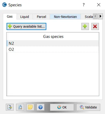
> Click on Species > select Gas > click on Add and select N2 &O2.
Simulation Parameters-
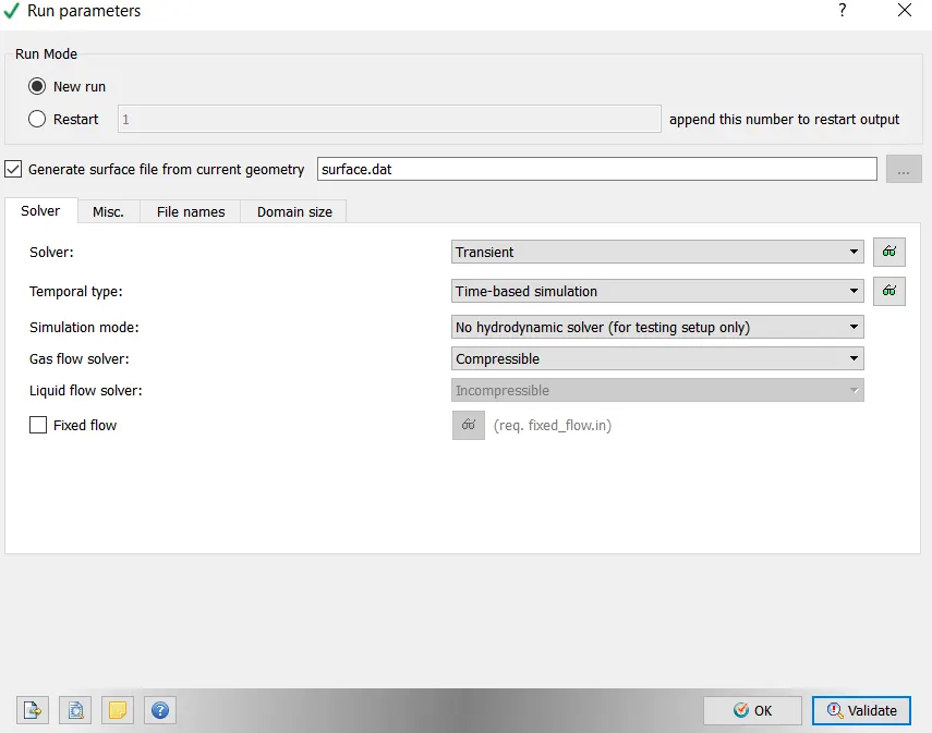
In Run Parameters two main things to be considered:-
(a.) select the following solver settings
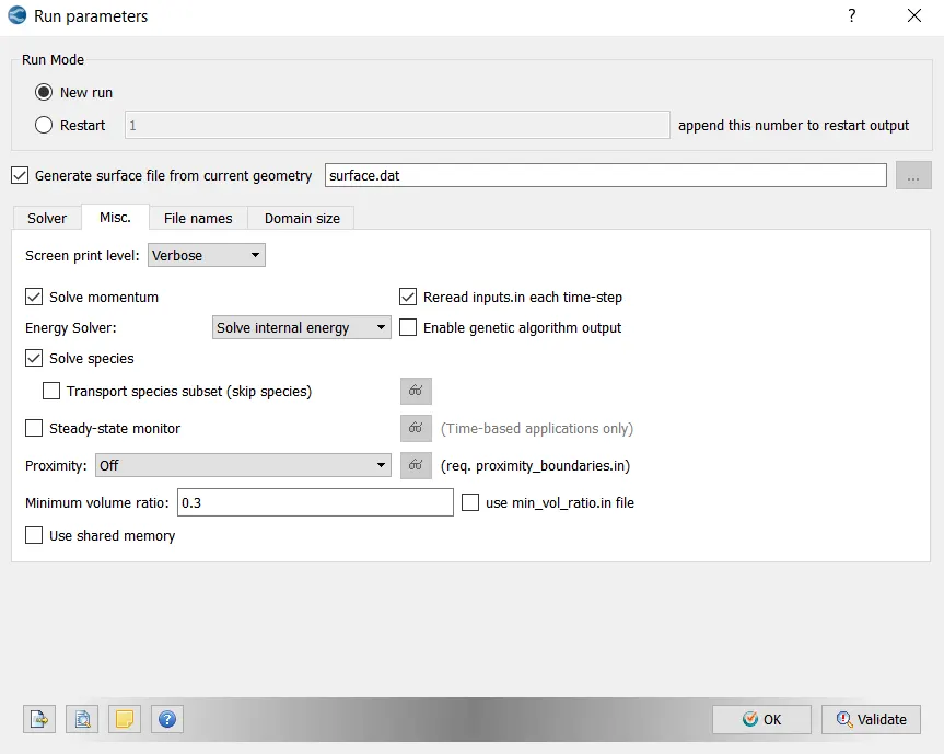
(b.) Go to Misc. > uncheck UseSharedMemory and un check Steady-State Monitor .
Simulation Time Parameters-
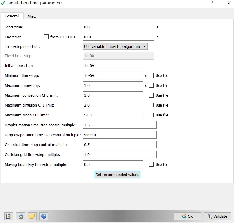
End time calculation:
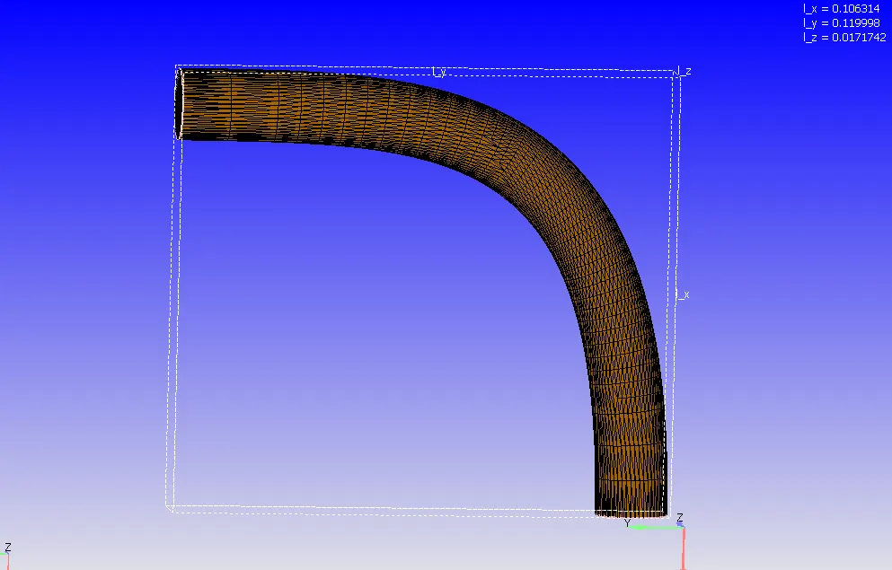
>> from the above contour:
length of pipe=0.2m
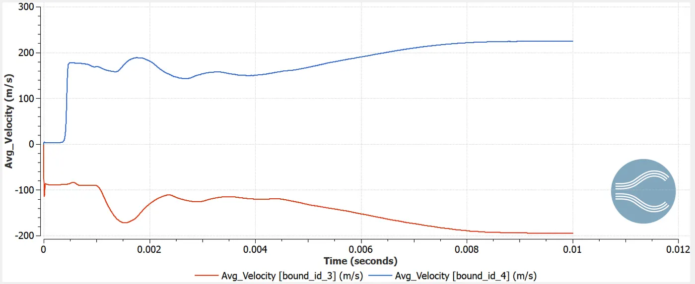
Avg.velocity=190m/s
{Speed=Distance/Time}
Therefore, Time=0.2/190
> Time=0.001sec
Here, run the cycle for 10times. So (0.001sec)*(10)=0.01seconds
Hence, End time=0.01sec.
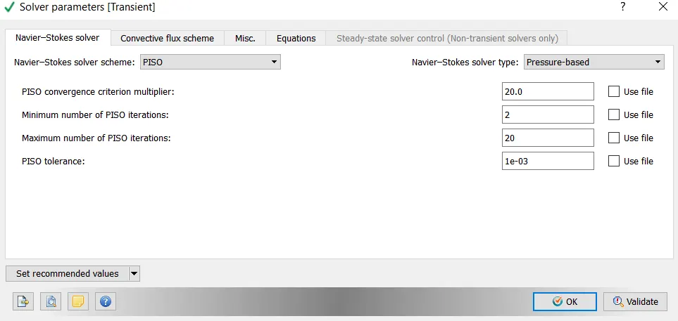
Solver Parameters [Steady-State]-
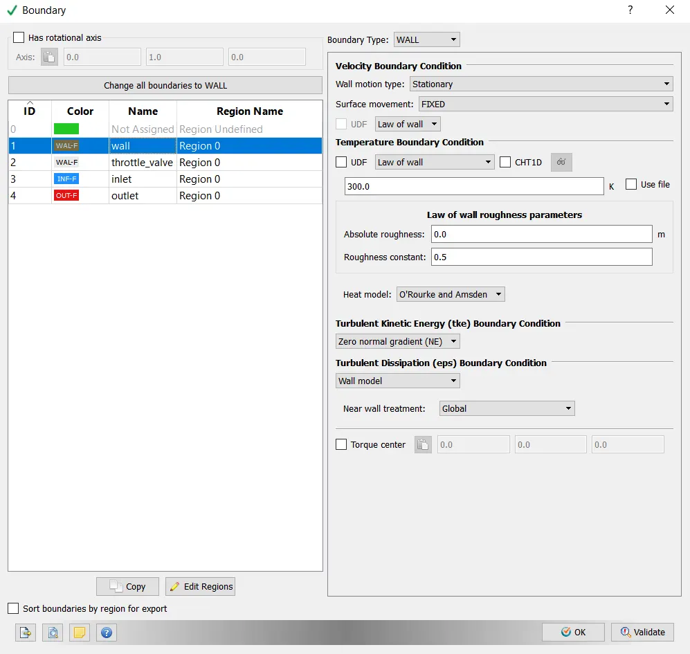
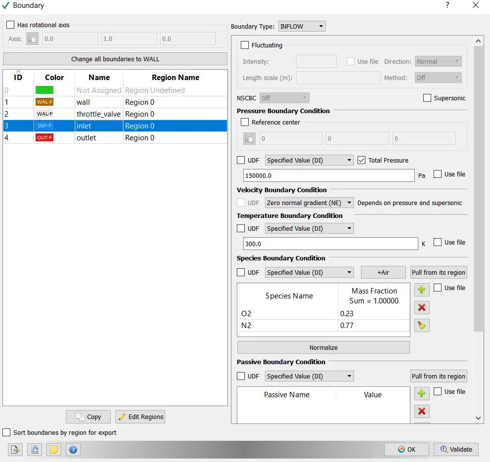
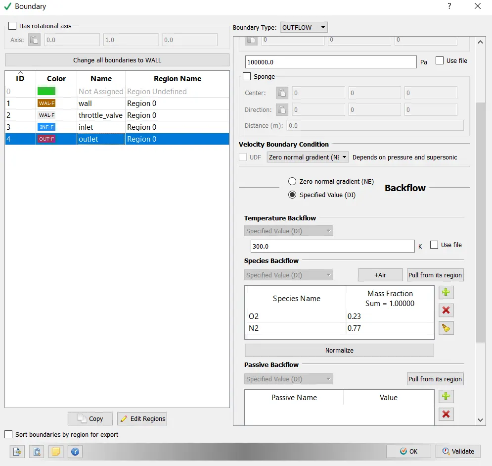
Boundary Conditions-
Booundary:
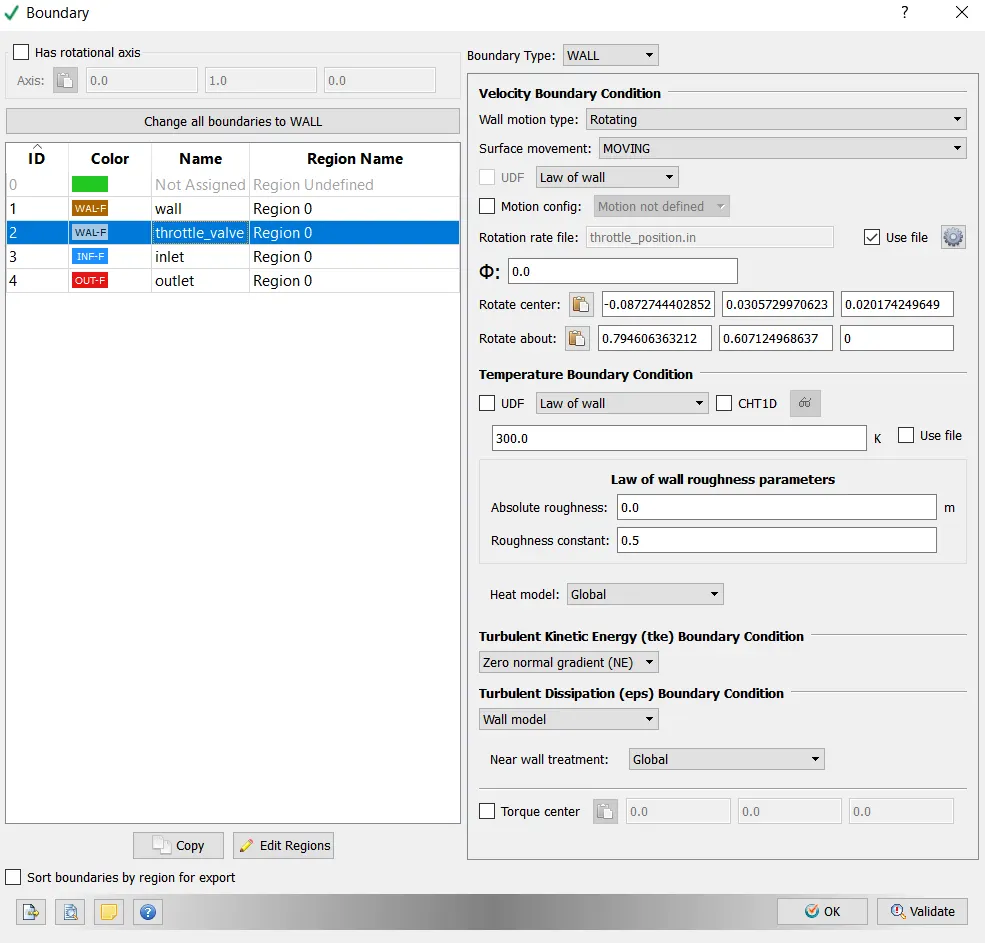
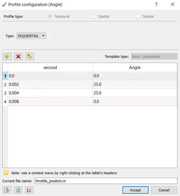
>> Setting up throttle movement:
- From 0 to 2 ms the valve should rotate by 25 degrees.
- From 2 to 4ms it should stay at 25 degrees.
- After which by 8ms the valve should get back to it’s original position.
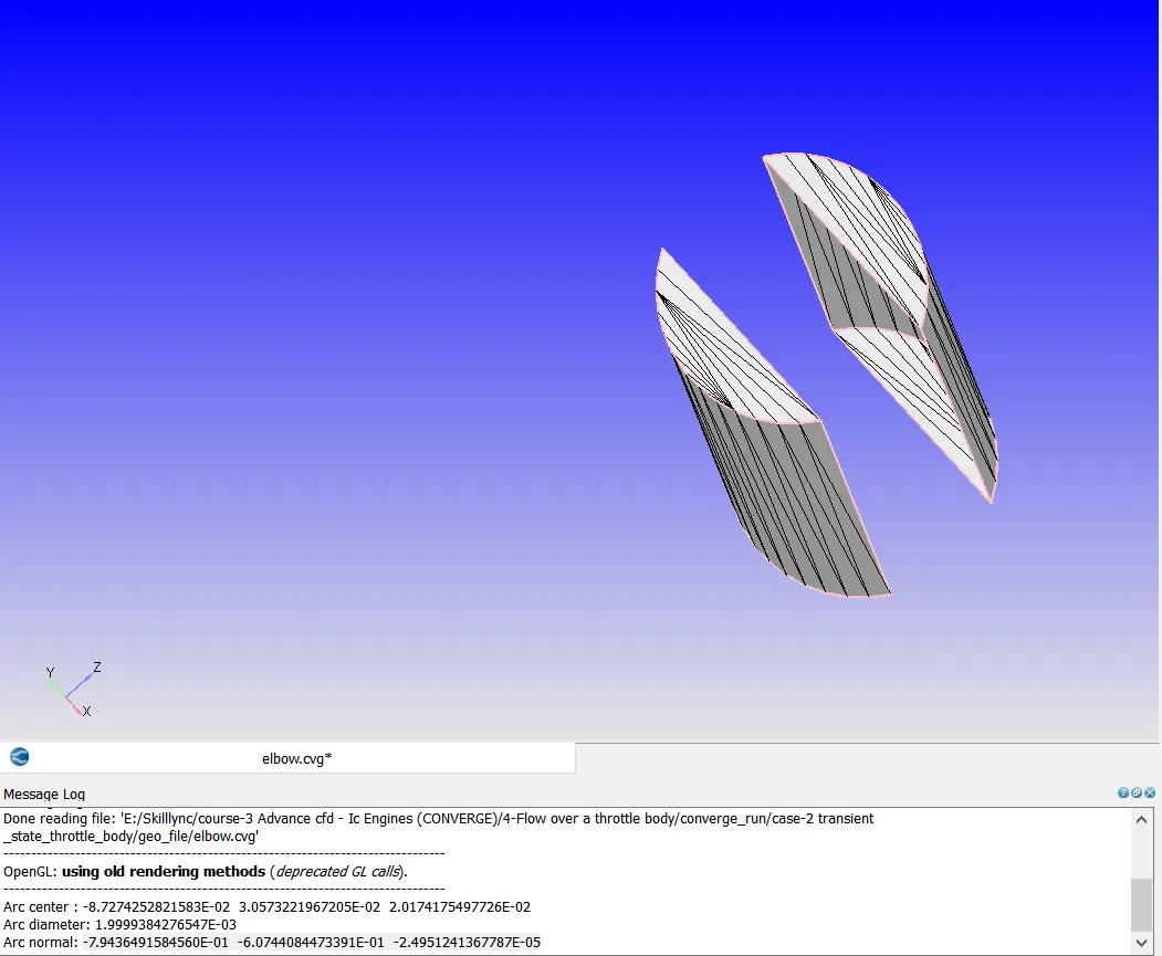
>> finding Rotation center and Rotation about values from the cylinder :
Initial Conditions and Events:-
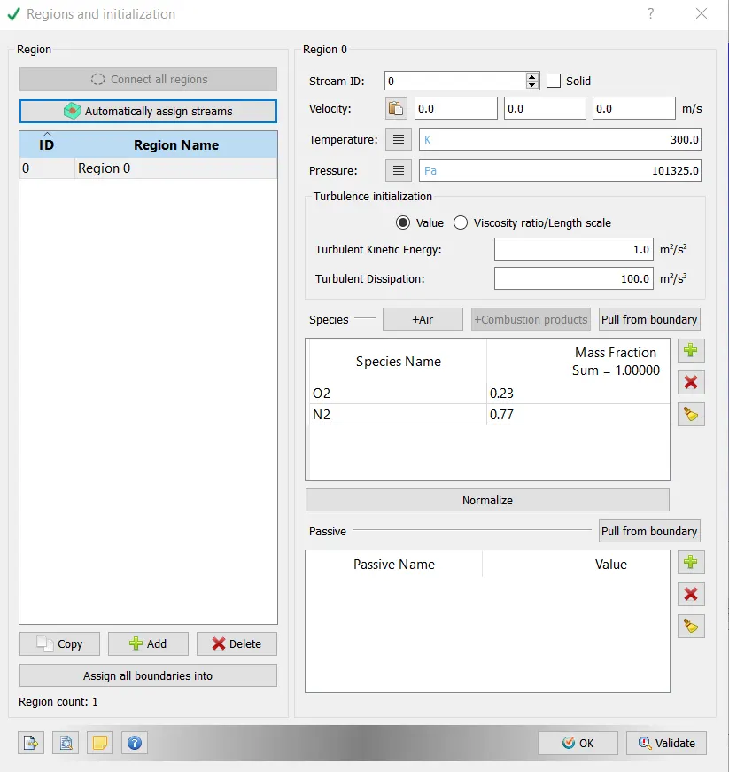
Regions and Initialization:
Physical Models:-
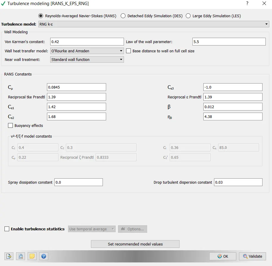
Click on Physical Models and select Turbulence Modeling in this case.
Turbulence modeling-
Grid Control:-
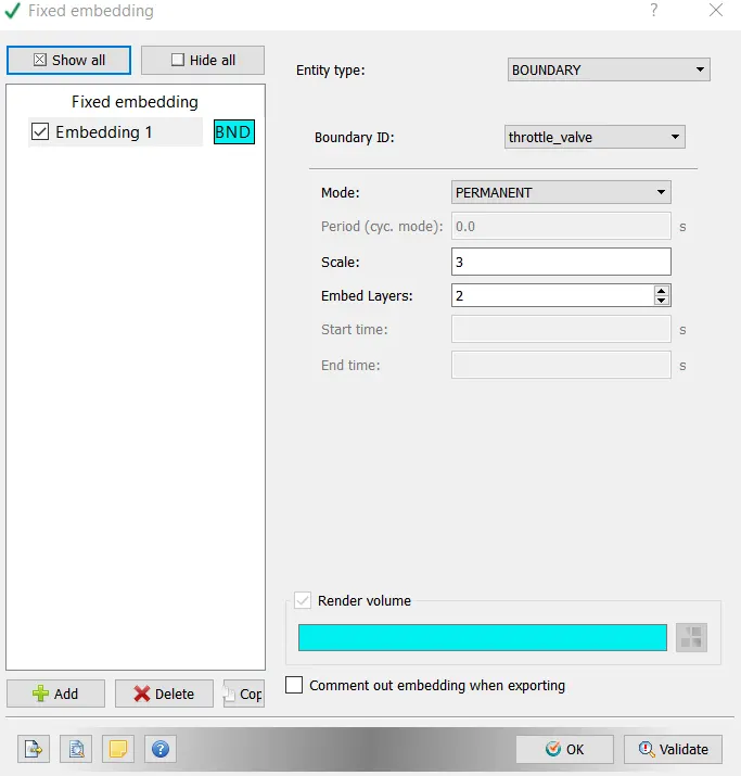
- Now click on Grid Control > select Fixed embedding.
Post-Processing:-
Post Variable Selection:
Click on Typical Variables/Geometry > Select required variables.
Output Files:
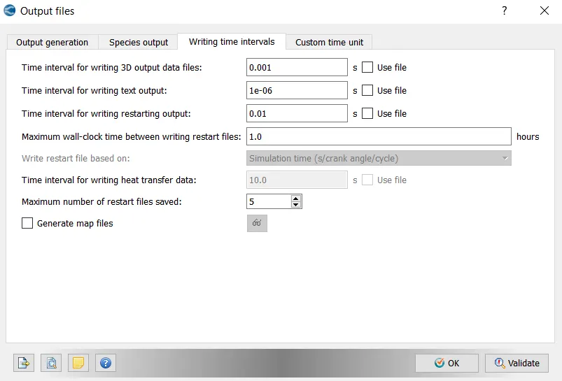
- With this setting up of the case is completed.
- Now go to File > Export > click on Export Input Files. select the destination folder(test) to save the data.
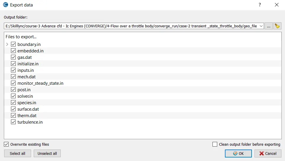
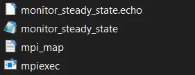
- After importing the input files, paste the "mpiexec.exe file".
- Now open Cygwin and navigate to the location where the setup files are imported.
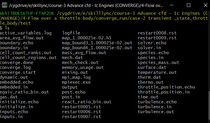
- Once we navigate to the respective folder, we need to run the simulation. To run the simulation use the following command in Cygwin;

>> Here path is copied from " C:ProgramFilesConvergent_ScienceCONVERGE3.0.15binconverge-intelmpi.exe ".
- Now the simulation starts running , and it displays the steps in cygwin. As the simulation begins it creates multiple folders (i.e. '.scratch' & output) in the path where we saved the input files.
- Once the simulation is complete, to perform post processing we need to convert the obtained result data into format where we can access in Paraview. These converted files are directed to the Output folder.
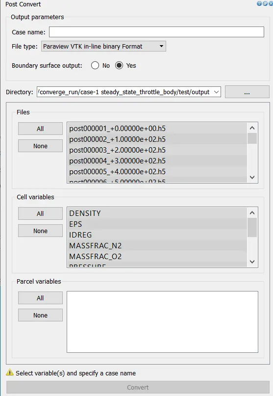
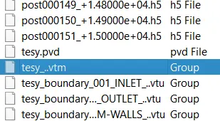
- Open PARAVIEW > direct to folder where the output is saved > select '.vtm(group file)' > data imported to paraview.
- Necessary contours, profiles and animations are generated using paraview. To generate plots we can use ConvergeStudio (line plotting option).
- Hence required plots, contours , animations are obtained in order to study the results.
Geometry:
Case Setup:
Observation:
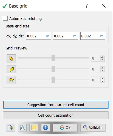
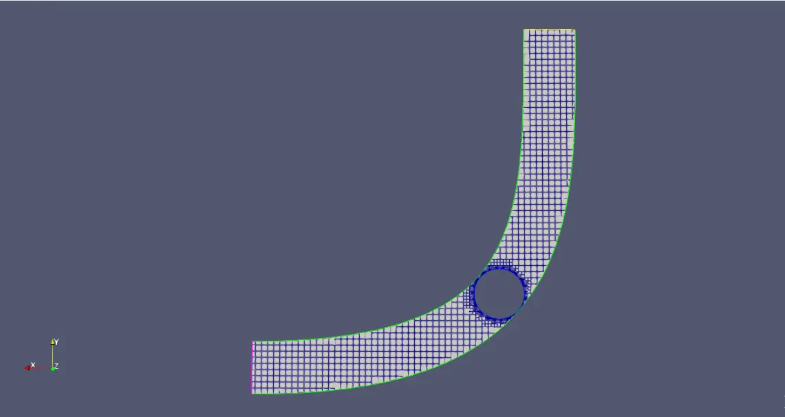
Gride size : dx=0.002, dy=0.002, dz=0.002
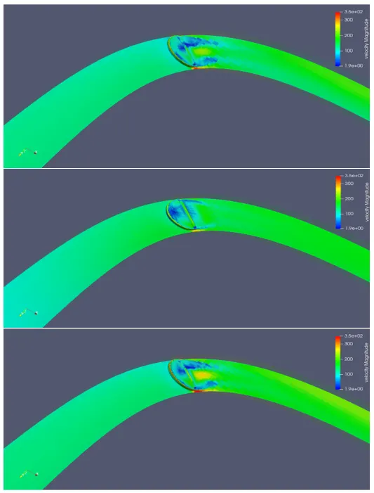
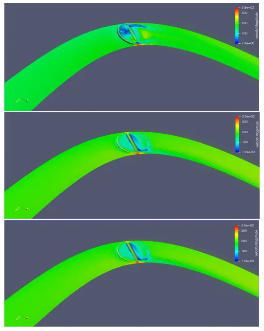
Velocity Contour:
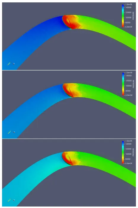
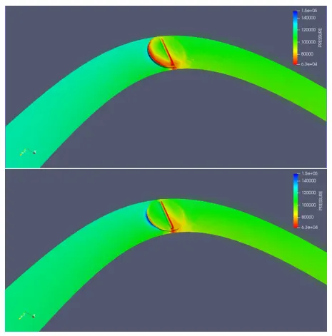
Pressure Contour:
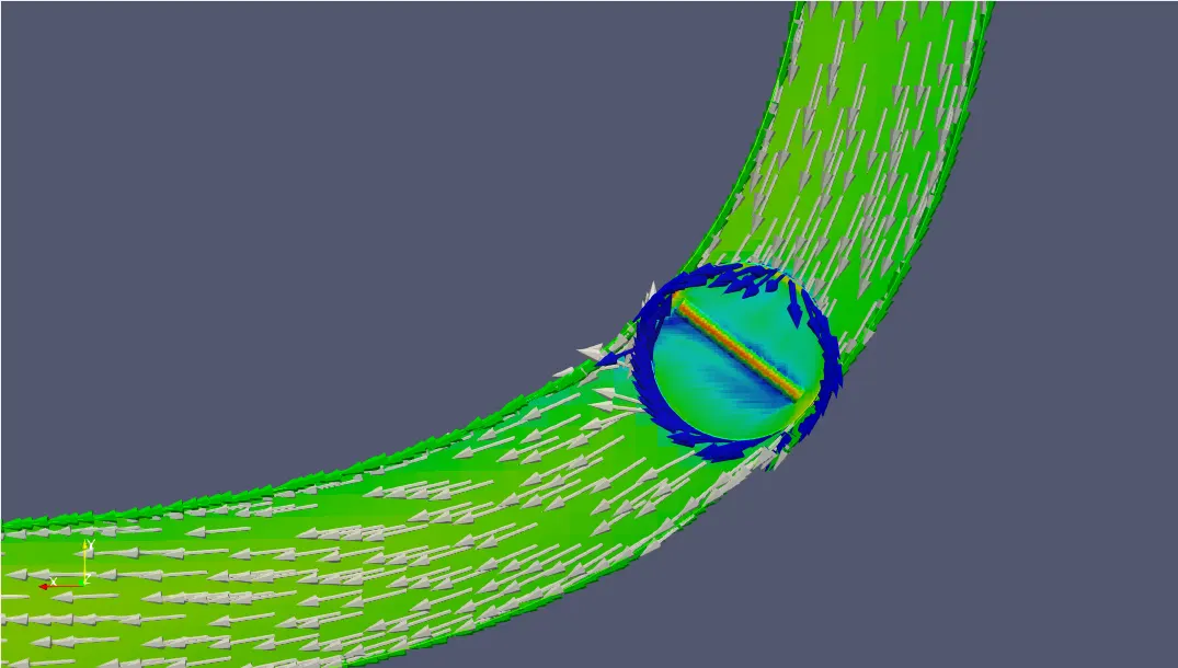
Velocity Vector:
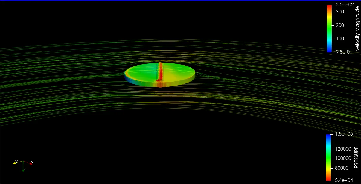
Velocity Stream lines over the throttle valve:
Velocity Plot:
Pressure Plot:
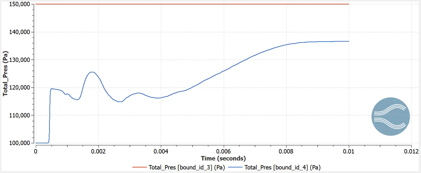
Total pressure-
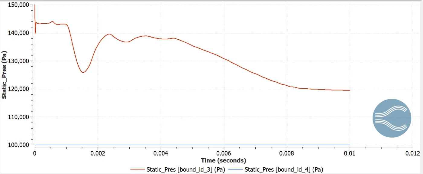
Static pressure-
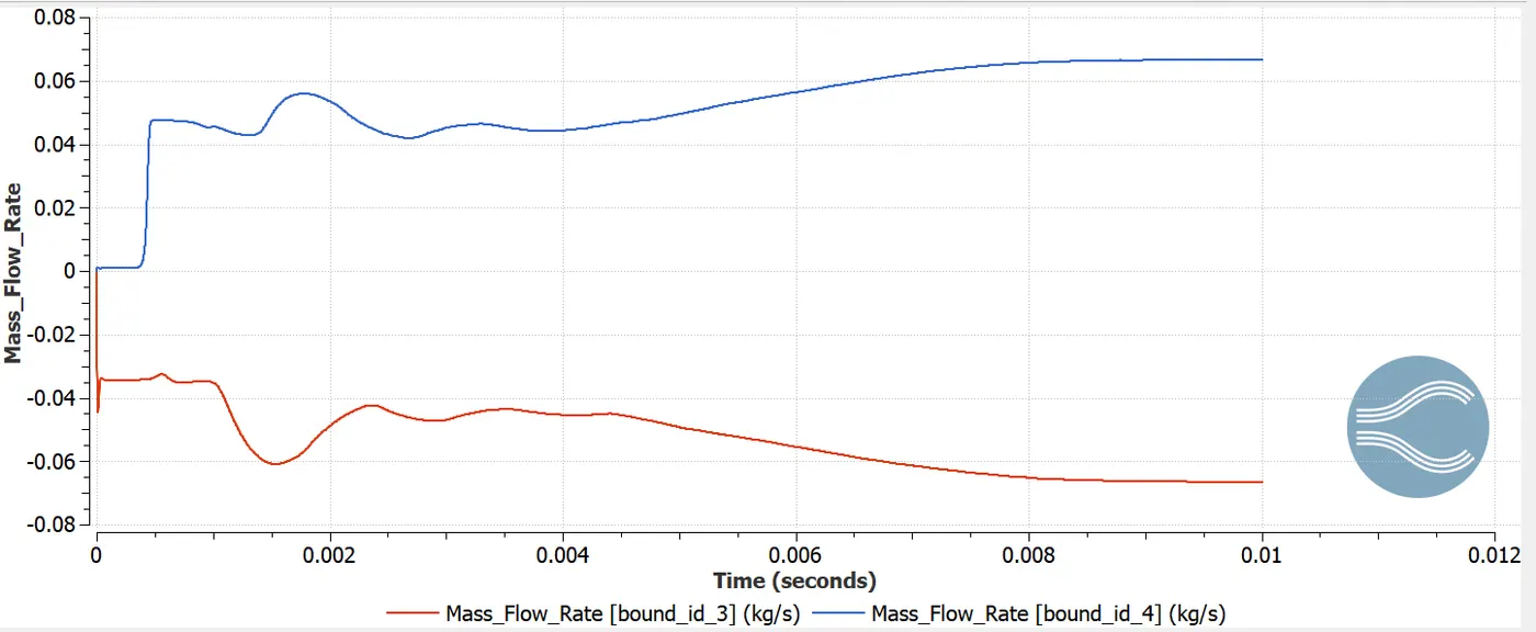
Mass flow rate plot:
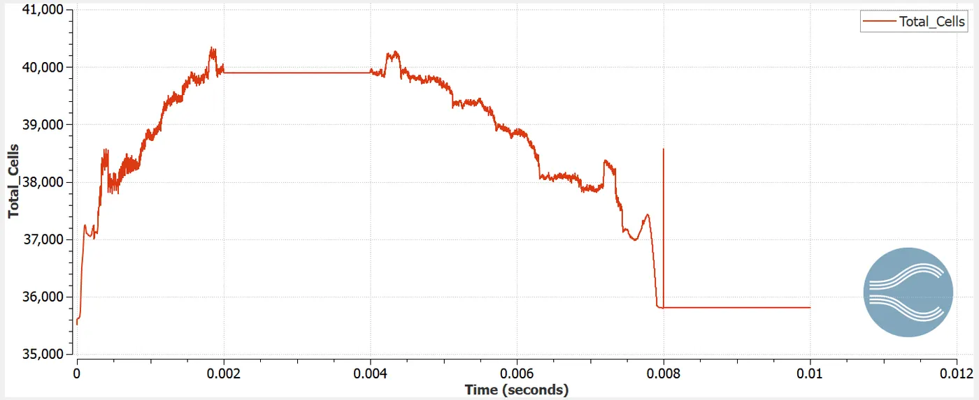
Total cell count:
Animation:
Velocity:
Pressure:
Results:
- From the above contours it is clear that, on giving the fine mesh to the valve the contours appear more details and the results are highly accurate.
- The flow through the throttle position is more accurate as the mesh generated along the throttle position is refined (having more cells surroding the valve) i.e. by providing 2embeded layers and a scaling of 3 to the mesh.
- The contours show that, there is a restriction to the flowof intake air that is caused by throttle plate.The inflow mass flow rate is balanced by the outflow rate.
- If there is less restriction in the flow , then there is a lower loss in energy. Hence because of this the velocity at outlet increases.
- As we have a moving mesh, number of cells generated are more and hence simulation time is high.
CONCLUSION:
The transient simulation-flow over a throttle body is performed using converge CFD. With finer refinement of mesh the accurate results are obtained . Various plots, contours and animations are generated to study the flow over a throttle body. Throttle movement is also captured for better understanding of flow.