Week 4:- Pin Unit Design Challenge
AIM:-
- To design 2 different types of fixed pin units with different pins, riser, blade & block, and 2 different types of retractable pin units with different pins, riser, blade, cylinder & block.
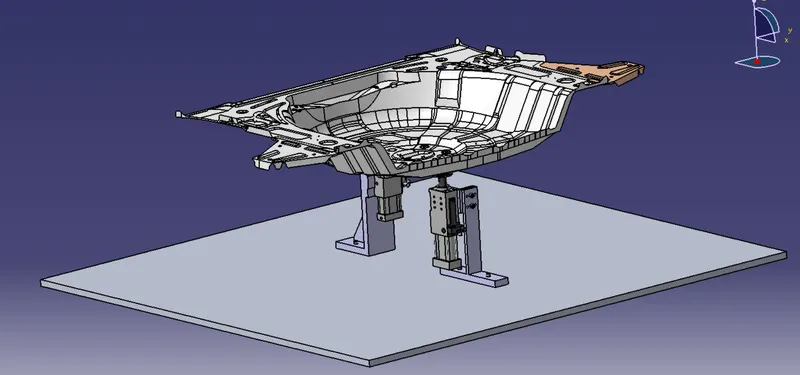
TYPES OF PIN UNITS:
- Fixed pin unit- In this type of unit, the pin is fixed by means of a pin retainer & riser.
- Retractable pin unit- In this type of unit, there is the provision of moving of pin in the up-down direction.
FORMULA & CALCULATION:
Formula to calculate the length of the screw,
Length of the screw = [1.5 X (std. hole size)] + {distance between the surface of the part to the first surface of the other part}
Example:
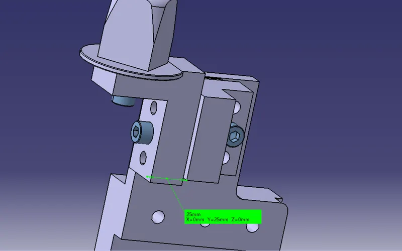
Figure 2. Length calculation for the length of the screw.
- To fix the pin retainer & the shim block using standard screws we need to find the length of the screw using the above-mentioned formula.
- The highlighted surfaces shown in the figure are the {distance between the surface of the part to the first surface of the other part}
- Since the given tap holes are M8 & the distance is 25mm as shown in the figure then,
- Length of the screw = [1.5 X (std. hole size)] + {distance between the surface of the part to the first surface of the other part} Length of the screw = [1.5 X 8] + 25 = 37 = 40mm Allen cap screw
- Then the standard size of the screw should be 40mm for connecting the pin retainer & the shim blocks for this example.
MATERIALS USED:
In general, the materials used for pins, pin retainers, shims, shim block, blades & risers are:
- Pin: C45, EN31, SAE 8620 Steel,
- Pin retainer : Steel / ASTM A-36, SS type 303 or 304,
- Shims/spacer: S.A.E. 1010 CRS FULL HARD, COLD ROLLED STRIP STEEL S.A.E. 1010 FULL HARD, S.A.E. 1020 HRS, etc.
- Shim block : STEEL ASTM A-36, NM Stainless, STEEL ASTM A-36, SS type 303 or 304,
- Blade : STEEL ASTM A-36,
- Riser : STEEL ASTM A-36,
HARDNESS:
In general, the hardness of the materials for pins, pin retainers, shims, shim block, blades & risers are:
- 55 - 60 HRC / 58 - 62 HRC to a depth of 0.5 - 0.7 mm after grinding.
SURFACE FINISH:
In general, the hardness of the materials for pins, pin retainers, shims, shim block, blades & risers are:
- Pin: Chrome plating, Zinc coating, Pins with TiN codes shall have 1 to 2 microns of nitride added to
- Pin retainer: BLACK OXIDE FINISH, No black oxide finish for "SS TYPE" components (SURFACES TO BE FLAT, PARALLEL &
PERPENDICULAR TO O WITHIN 0.015 T.I.R).
- Shims/spacer: BLACK OXIDE FINISH (SURFACES TO BE FLAT AND PARALLEL TO WITHIN 0.015 mm T.I.R).
- Riser: SURFACES TO BE FLAT, PARALLEL & PERPENDICULAR TO WITHIN 0.015 T.I.R.
PIN TOLERANCE:
The pin tolerance for a geo pin will be of closer tolerance i.e -0.15mm & for respot, the pin is -0.28mm.
PURPOSE OF PIN UNIT:
- As by the 3-2-1 locating principle, the introduction of two pins helps to arrest the 6 degrees of freedom (4 axial & 2 radial movements) whereas the other 6 degrees of freedom are arrested by introducing a minimum of three supports.
- Typically, the locating pins are used to locate a body part in a position sufficiently accurate to execute a welding process.
- The body part is constrained by a set of appropriately locating pin so total constraint by locating pin should be fully constrained at all times to prevent any movement.
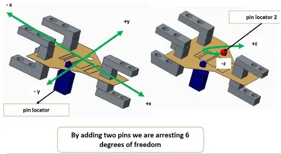
Figure 3. 3-2-1 Principle concept (Arresting 6 DOF by introducing 2 pins) \
FUNDAMENTALS OF PIN UNIT DESIGN:
It is necessary to have two pins to locate a car panel. And here one pin must arrest 4 way (i.e 4 translation) & the other must-have arrest 2 way (i.e 2 rotational) of a car panel.
- The pin should engage 3 to 5mm from the car part entry
- All pin should be accommodated with 2-way adjustable shims irrespective of the direction of
- The round pen should be used in case of 4 way arresting of car panel if the hole is
- The round pin can be used for 2 way arresting of car panel only if the hole is
- The diamond pin should be used in case of 2 way arresting of car panel if the hole is
- The diamond pin should be used in case of 4 way arresting of car part if the hole is
- The axis of the car panel hole & the axis of the pin should be the same in
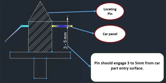
Figure 4. This shows the 1st point in the fundamentals of pin unit design.
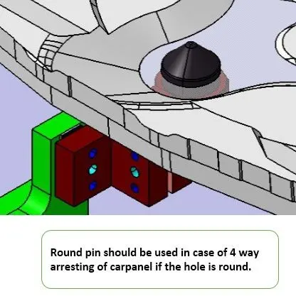
Figure 5. Shows the 3rd point in the fundamentals of pin unit design.
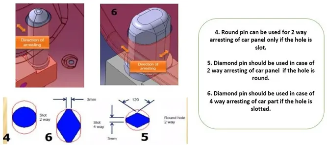
Figure 6. Shows the 4th, 5th & 6th points in the fundamentals of pin unit design.
Following are the requirements that need to be taken into account while designing the parts
1)Pin- Pin is the part that locates the car panel. It can be a make part of standard part.
- The pin should be grinding surface on a shaft with fits on to which the pin retainer will be fitted.
- The mounting surface of the pin should be a finely machined surface.
- The pin should have a step machine surface to lock the rotation, which matches with the pin retainer
- All machined planes should be perpendicular to the axis of the pin shaft.
- Pin must have a provision like a tapped hole from the bottom or a v-groove from the side.
- A pin must be hardened (Heat treatment) & black oxide finished in general.
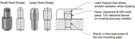
Typically, locating pins are used for controlled, fine tolerance positioning of a, For example, a pallet that is moved along one axis, where the drive mechanism is not accurate and stable enough to place it in a position sufficiently accurate to execute a particular process, the use of locating pins may be the best solution.
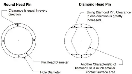
The Diamond Shape is a critical feature that helps with machining inaccuracies and smoother locating When two round headpins are installed onto one plate, the distance between two mounting holes must be extremely precise and even then, the workpiece will not be placed on the base as easily as it would with the use of a diamond shape pin.
There are several styles of Pin Head They serve different purposes and can be utilized in a variety of applications.
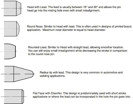
2. Pin Retainer- A pin retainer is a part which holds the pin in position, the pin retainer can either be a make part of a standard part.
- Pin retainer should have a hole with a fit, on to which the pin will be fixed
- The pin mounting surface of the pin retainer should be a machined surface.
- The pin mounting surface of the pin retainer should have a step to lock the rotation of the pin
- The pin mounting surface of the pin retainer to the blocks should be a machined surface.
- The pin retainer will be fixed to a block or an L block to the riser with 2 dowel holes (pins) & at least one screw hole to maintain the tolerance.
3. Block/L Block-
- These parts are mainly used to accommodate the shimming directions as per fundamental in general. Also in some cases used for other design feasibility.
4. Shims/Spacers-
- Shims & Spacers are some standard parts in general, which are used for adjustments of locators(NC Blocks & pin retainers) for desired values for the precise working of a unit with respect to car part. In general to adjust the design to manufacturing deviation.
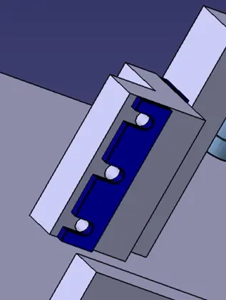
5. Blade-
- A blade is part like a plate, which connects the parts on a unit to an In general, the blade can be either a make part or a standard part.
6. Riser-
- It is a part on which all the parts of a unit are mounted & is mounted on the base plate of a tool.
7. Dowel holes & machined surface-
- All make parts which are to be assembled should be designed with 2 dowel holes & at least of 1 to 6 threaded/ free hole(depends on size) 7 to be finely machined for the mounting surface with 3 to 5 mm step machining.
Designed fixed pin units-
Figure Shows the Principle Locating Point (PLP) in fixed pin unit.
Principle locating points is a hole in which we locate the panels. PLP holes must be very much precise.
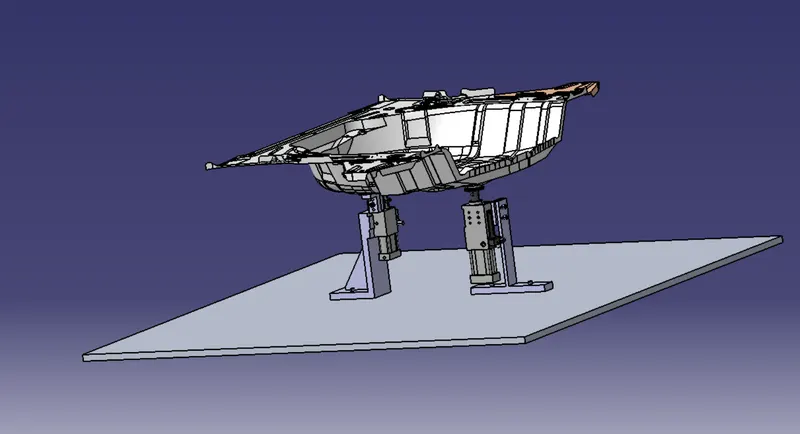
Figure Shows the component with retractable pin units
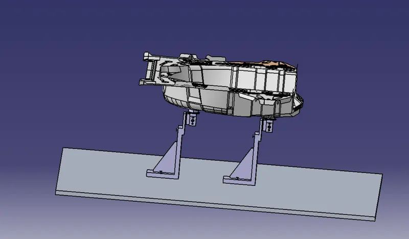
Figure Shows the component without retractable pin units
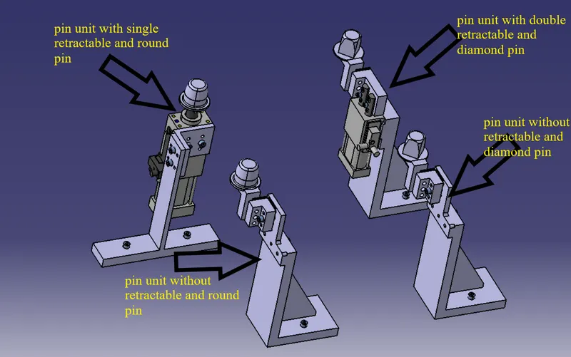
Figure Shows the retractable and without retractable pin units.
CONCLUSION:
Hence, As per the objective, the 2 different types of fixed pin units (P001_Z01_ST010_01_00) & (P001_Z01_ST010_03_00) with different Pins, Pin retainer, Blades & risers & 2 different types of retractable pin units (P001_Z01_ST010_04_00) & (P001_Z01_ST010_05_00) with different Pins, Pin retainer, Blades, risers & cylinders are designed and rendered using CATIA V5 successfully.