Week - 4 - Crash Box Simulation
AIM :
To create a complete simulation file using Input Parameters from this to perform a Crash Box Simulation and Plot the Output results.
OBJECTIVE :
--> Input Parameters required for the simulation are listed below,
- Title Card,
- Section,
- Material Card,
- Part,
- Initial Velocity,
- Contact,
- Control Card
--> Obtain the required Output results such as
- Input .k file and output files (d3plot, glstat, sleout, rcforc)
- Animation of the final simulation
- Cross-sectional force generated in the middle of the crash box (along its length)
- Acceleration plot of a node in the middle of the crash box (along its length)
- Maximum directional stress and strain along the length of the crash box (X strain, Y strain etc)
- Plot of all energies (total, internal, kinetic, hourglass, sliding)
- Compare the accelerations and stress/strain plots of 1.2/1.5mm crash boxes.
PROCEDURE :
1. Import the given Model in LS-PrePost using File-->Open-->LS-DYNA Keyword File option.
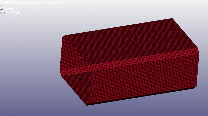
Fig: Imported Model
2. After Importing a Model, Set the Input Parameters using Model-->Keyword Manager option.
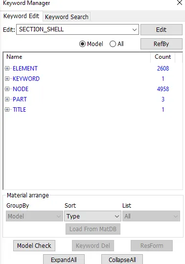
Fig: Keyword Manager
Title :
3. Create a Suitable Title for the simulation by using Keyword Manager-->Model-->Title option,
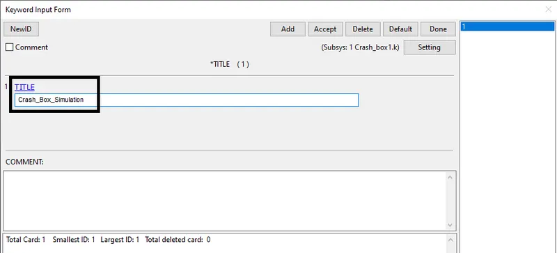
Fig: Creating a Title
Section :
4. Create a Section for Bottom Plate(Shell) and Phone(Solid) part.
5. Go to Keyword Manager-->All-->Section-->Shell option,
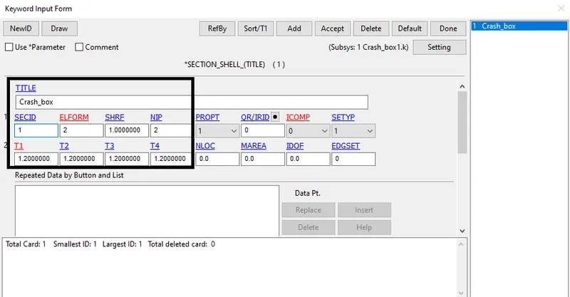
Fig: Section for Crash Box (Shell)
Material :
6. Create a Material for Bottom Plate and Phone.
7. Go to Keyword Manager-->All-->MAT-->024-Piecewise Linear Plasticity option,
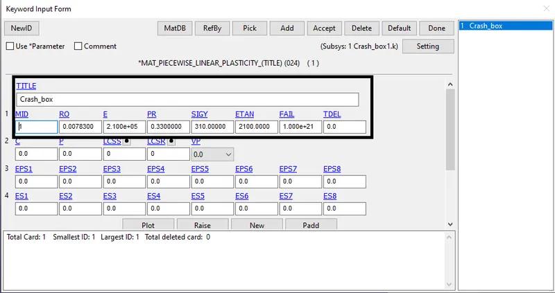
Fig: Creating Rigid Material
Part :
8. Create a Part by using Keyword Manager-->Model-->PART option and assign the Section ID & Material ID,
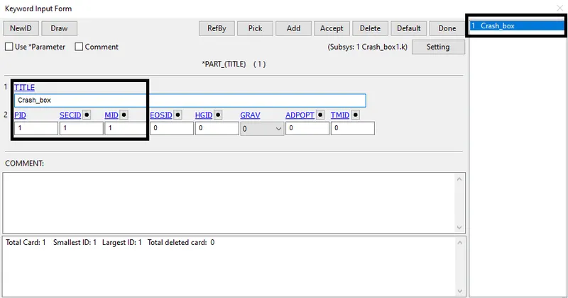
Fig: Creating a Part
Rigid Wall :
9. Create a Rigid wall by using Create Entity-->Rigid wall option and select the Planar option.
10. Use the 1n+NL option and select the node on a crash box to create a rigid wall.
11. Use the Tran option and assign the distance of the rigid wall away from the crash box.
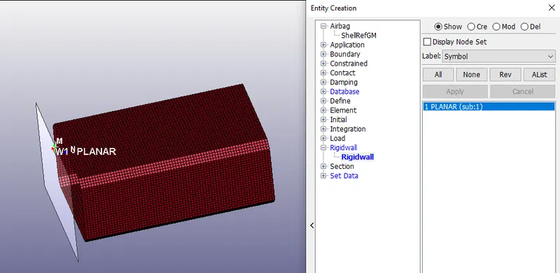
Fig: Creating a Rigid Wall
Initial Velocity :
12. Create an Initial Velocity for Phone by using Keyword Manager-->All-->INITIAL-->Velocity option,
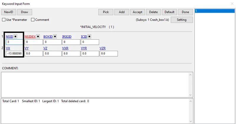
Fig: Creating Initial Velocity
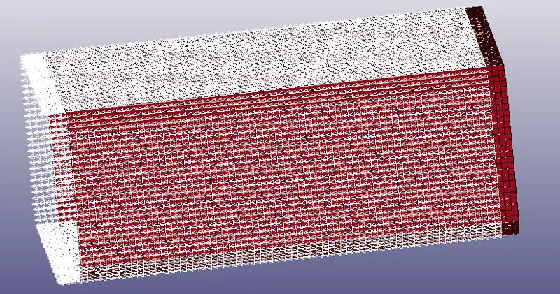
Fig: Velocity towards X-direction (negative)
Contact :
13. Create a Contact using Keyword Manager-->All-->Control option,
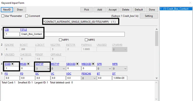
Fig: Creating a Contact
Control :
14. Create a Control card using Keyword Manager-->All-->Control-->Termination option,
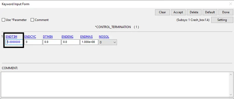
Fig: Creating Control Card
Cross-section :
15. For generating sectional force in the middle of the crash box, create a Cross-section.
16. Go to Create Entity-->Set Data-->*Set_Node for node-set and Create Entity-->Set Data-->*Set_Shell for Element or Shell set.
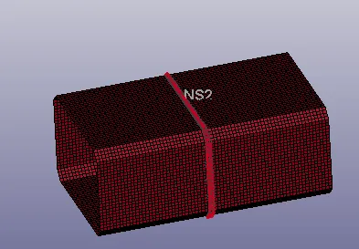
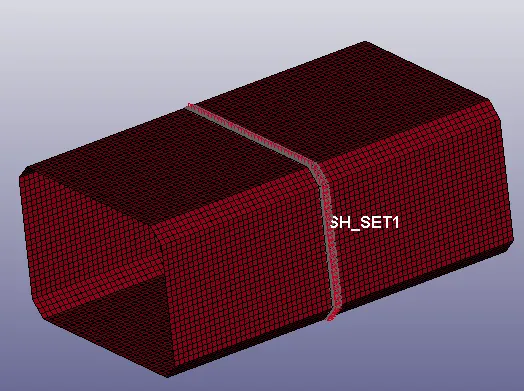
Fig: Creating Cross-section (Node-Set & Shell-set)
Output Requests :
17. Create an Output request to obtained plot results from the crash box simulation.
18. Go to Keyword Manager-->All-->Database-->Binary_D3Plot option and set the time step(Dt),
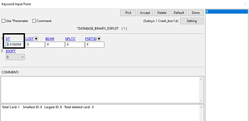
Fig: Time Step for getting output Plot results
19. Go to Keyword Manager-->All-->Database-->ASCII_option and Select GLSTAT option and set Dt value to get Energy plot results,
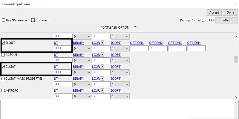
Fig: Time Step for getting Energy Plot results
Model Check :
20. Finally, Check the Model for Errors and Warnings using Keyword Manager-->Model Check option,
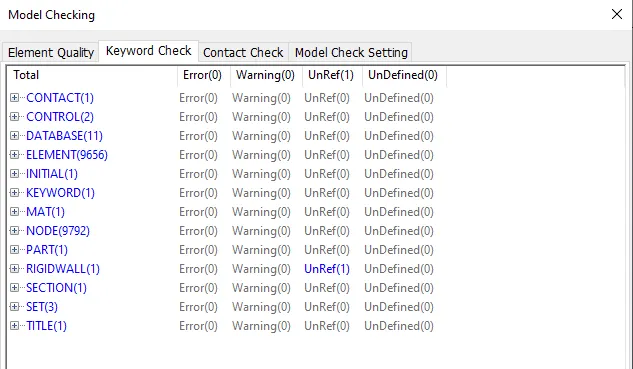
Fig: Model Checking
21. After Model Checking, Run the Simulation using File-->Run LS-DYNA option,
22. In the LS-RUN window, import the keyword file and Run the simulation.
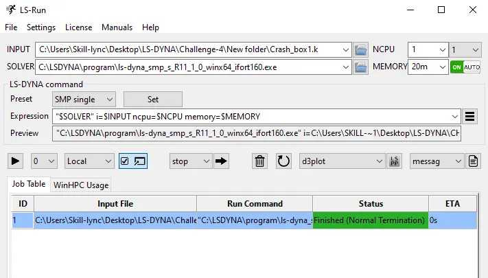
Fig: LS-Run Window
OUTPUT RESULTS :
23. Finally Simulation finished by Normal Termination and Output results has been displayed below,
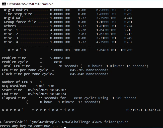
Fig: Output Result
Energy Plot :
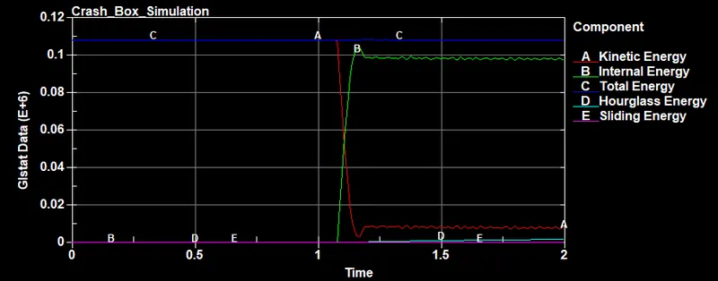
Thickness = 1.2mm
Thickness = 1.5mm
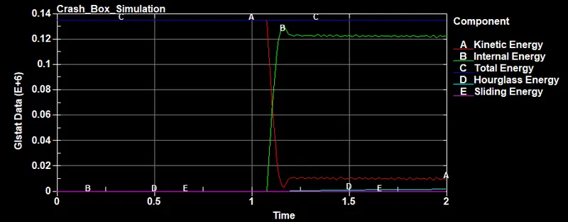
- For the first 1.1 ms, there is no crash between Box and Rigid Wall, After 1.1 ms Crash starts and Internal Energy starts to gain the energy from the system due to changes in its internal state, and Maximum Internal Energy is 0.110E+6 (for T=1.2mm) and 0.13E+06 (for T=1.5mm) is generated.
- The Maximum Kinetic Energy of the system is at t=0ms(no deformation at the time), Kinetic Energy starts to lose the energy of the system at t=1.1ms.
- We Know that Total Energy remains constant(no loss or generation of energy), Kinetic Energy decreases while Internal Energy Increases. Due to the tiny mass added, less Hourglass Energy is created. Hourglass Energy is negligibly small. So that Total Energy is 0.115E+06 (for T=1.2mm) and 0.135E+06 (for T=1.5mm) is constant throughout the simulation.
- Here the contact keyword is only mentioned as the Automatic_single_surface for the crash box so the force due to contact will not be recorded and if you see the DATABASE_ASCII_RCFORC and the DATABASE_ASCII_SLEOUT will not return any value as plot since the rigid wall part is undefined ie, the master part ID. So we see the value of Sliding energy as zero in the graph.
Cross-Section Plot :
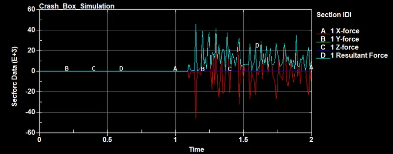
Thickness = 1.2mm
Thickness = 1.5mm
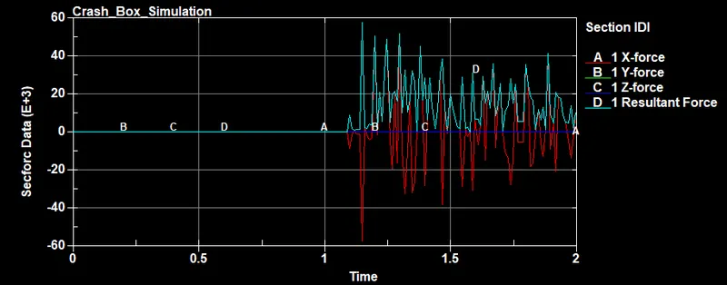
- From the above Cross-Section plot observed, the Sectional force is created for the middle of the Crash_box and we can see that the force value at the Y and Z direction after impact is very low since the velocity value is in the X-direction. At the impact time, we can see that the force value in X-direction peaks up and goes down after the bounce-back of the crash box. Comparing both plots, a thickness of 1.5mm crash box is obtained more force than thickness 1.2mm crash box during the Crash Simulation.
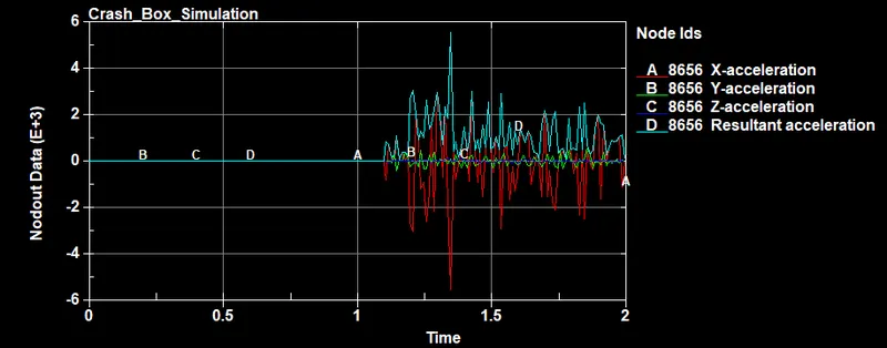
Acceleration Plot :
Thickness = 1.5mm
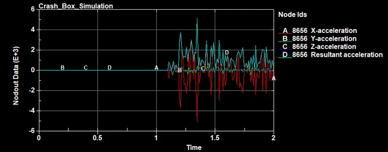
- From the above Acceleration plot observed, obtained the acceleration of node 8656 during the crash box simulation. We can see that the acceleration towards X-direction is negative since the accelerated body when came to impact there a deceleration happened. Here the value of deceleration in X-direction is nearly the same and the resultant acceleration is a magnitude and doesn't depend on the direction so we can see the positive value and almost equals the value of X-direction magnitude since the acceleration value in the Y and Z direction is very small.
Von mises Stress Plot :
Thickness = 1.2mm
Thickness = 1.5mm
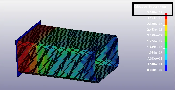
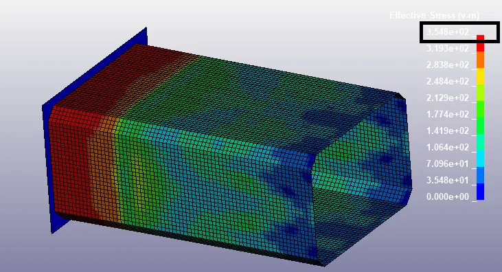
- The Effective Stress (von Mises stress) is used to predict the yielding of materials under complex loading from the results of uniaxial tensile tests. The von Mises stress satisfies the property where two stress states with equal distortion energy have an equal von Mises stress. The Vonmises Stress plot shows that, While Deformation occurs, Stress will be created and Maximum stress is 3.548E+02`N/(mm)^2`.
Effective Plastic Strain Plot :
Thickness = 1.2mm
Thickness = 1.5mm

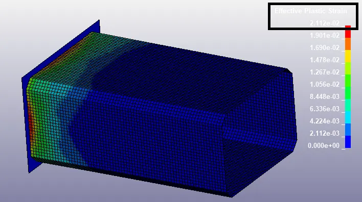
- From the above plot observed, the effective plastic strain rate shows that the amount of deformation that occurred during the crash simulation. The Maximum effective plastic strain rate is 2.112e-02 `N/(mm)^2` (for T=1.2mm thickness) and 2.111e-02 `N/(mm)^2` (for T=1.5mm thickness). Comparing the two plots, strain rates are similar.
X-Stress Plot :
Thickness = 1.2mm
Thickness = 1.5mm
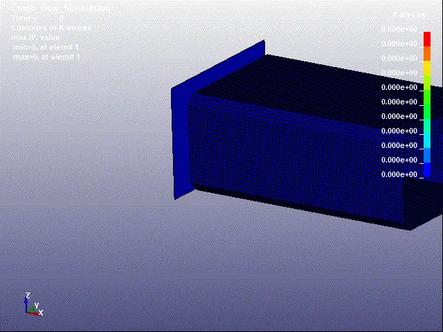
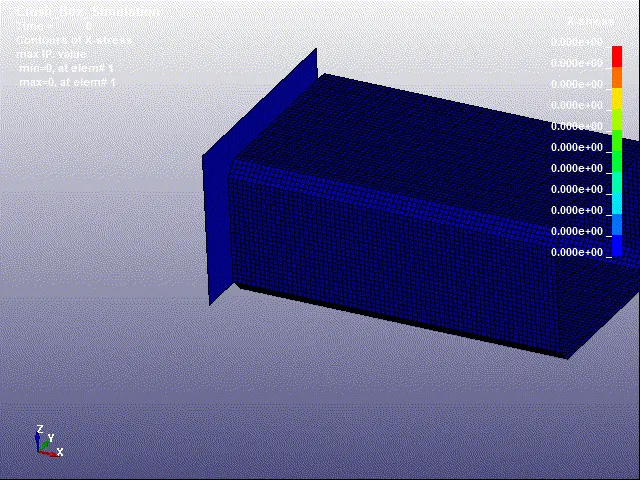
During the Crash box simulation, Box is impacting on the Rigidwall towards the X-direction, and stress in the x-direction is plotted. From the above stress plots, we can see the maximum stress is generated for thickness 1.2mm crash box than thickness 1.5mm crash box.
Y-Stress Plot :
Thickness = 1.2mm
Thickness = 1.5mm
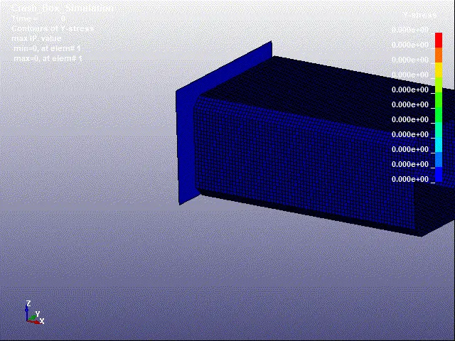
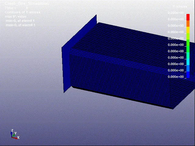
During the Crash box simulation, Box is impacting on the Rigidwall towards the X-direction, so stress generation in Y-direction is low. Stress is generated towards y-direction is plotted above for thickness 1.2mm crash box and thickness 1.5mm crash box is similar.
X-Strain Plot :
Thickness = 1.2mm
Thickness = 1.5mm
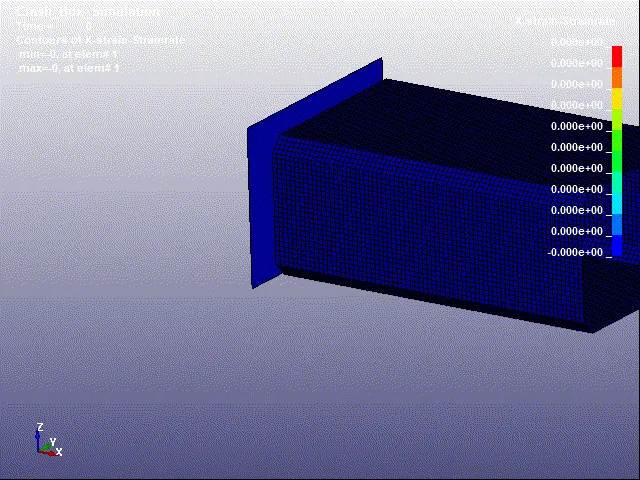
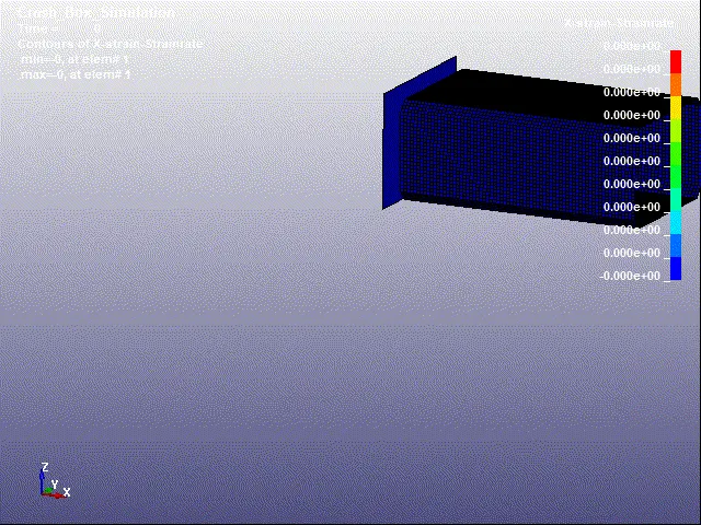
During the Crash box simulation, Box is impacting on the Rigidwall towards the X-direction, and deformation has occurred and strain rate towards x-direction is plotted. From the above strain plots, we can see the strain rate for thickness 1.2mm crash box and thickness 1.5mm crash box is similar.
Y-Strain Plot :
Thickness = 1.2mm
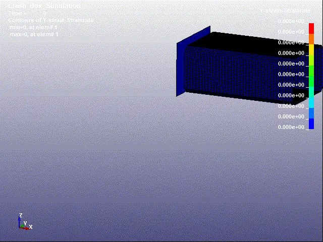
Thickness = 1.5mm
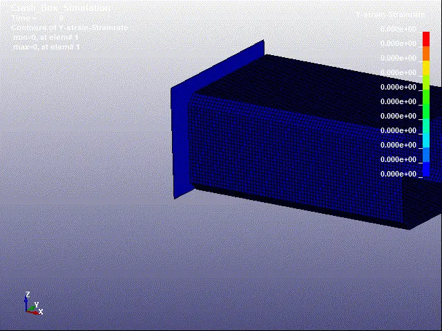
During the Crash box simulation, Box is impacting on the Rigidwall towards the X-direction, and deformation has occurred and the strain rate towards y-direction is lower than x-direction. From the above strain plots, we can see the strain rate for thickness 1.2mm crash box and thickness 1.5mm crash box is similar.
CONCLUSION :
The Crash box with the velocity of 50kmph is impacted on the rigid wall having a shell thickness of 1.2mm &1.5mm and obtained the output results for both cases and compared the output plots such as Sectional force, Acceleration, Effective Stress, Effective Plastic Strain, Stress & Strain for (X, Y direction) and Energy Plot.