Week - 4 - crash box simulation
AIM:
To run a simulation in lsdyna for different thickness assigned to the crash box and compare the results.
PROCEDURE:
The first step is to build the model using various keywords in form the keyword manager.
Firstly the section type is defined to the software by creating it with various thicknesses of 1.2 and 1.5.
Then the material card 024 piecewise_linear_plasticity is assigned as the material
The part is defined to dyna by assign the masterial and section id's.
Then the rigid wall is created under the entity creation-> rigid wall.
The rigid wall is offseted to distance of 2mm inorder to obtain a shorter computation time.
The respective termination time is also set as 0.01 ms with a dt of 0.0005ms
The database card is assigned for d3plot, glstat, sleout, rcforc.
Automatic single surface contact is assigned as there is contact between the rigid wall and the crashbox during the impact.
The spc is set for the crashbox by allowing the object ot move in the x direction alone as all the other dof's are arrested.
The initial velocity of -13.88mm/ms is assigned
Then the computation is processed with the help of ls run.
After a error free terimination of the keyword file, the d3plot file is animated in the ls prepost to obtain the various visual outputs and graphs.
The graphs for both the 1.2 mm and 1.5 mm thickness shells are shown below:
the folllowing graphs are shown for the time of impact:
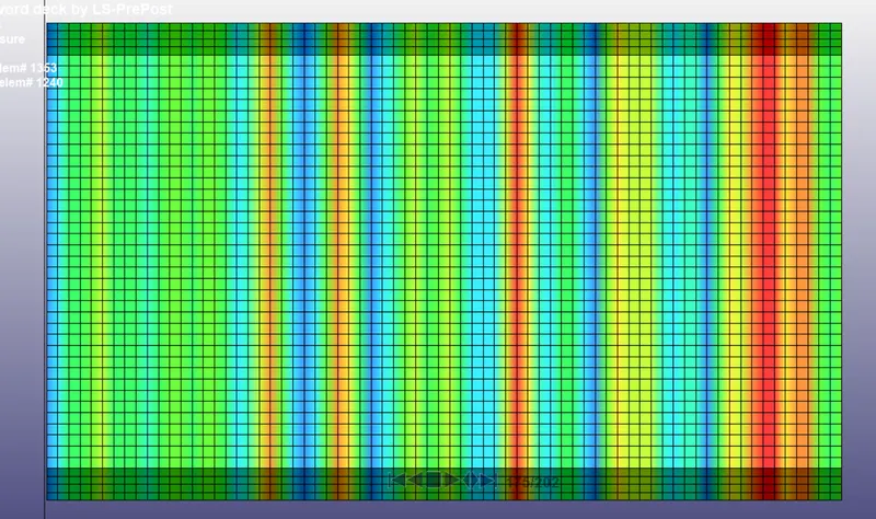
kinetic energy 1.2T
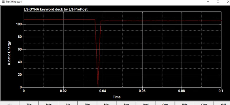
internal energy 1.2T
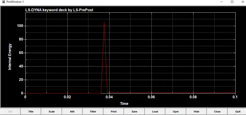
total energy 1.2T
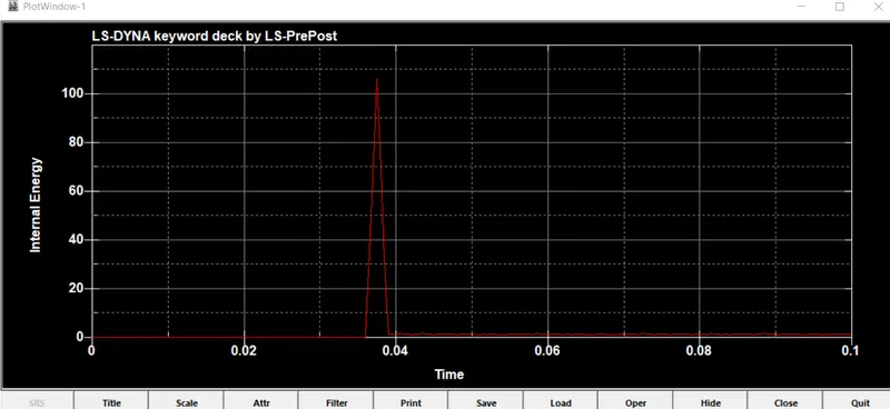
nodal energy 1.2T
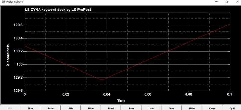
x-directional stress 1.2T
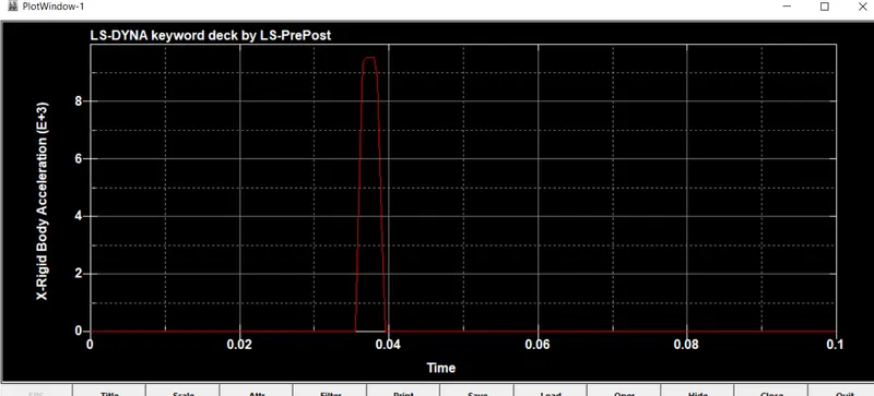
nodal accleration 1.2T
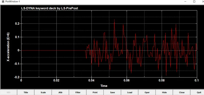
For the thickness of 1.5T.
kinetic energy 1.5T
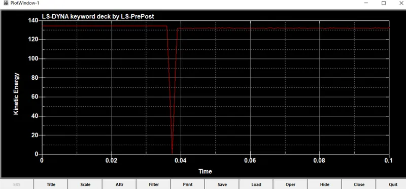
internal energy 1.5T
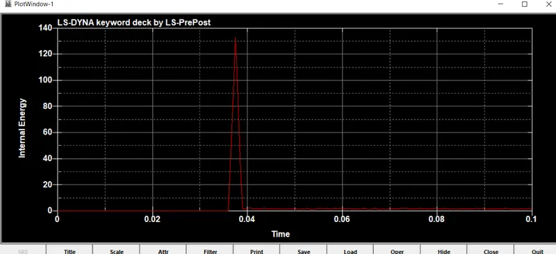
nodal energy 1.5T
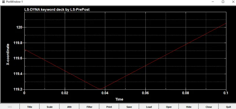
total energy 1.5T
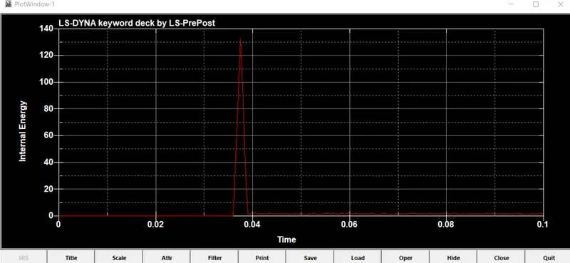
x-directional stress 1.5T
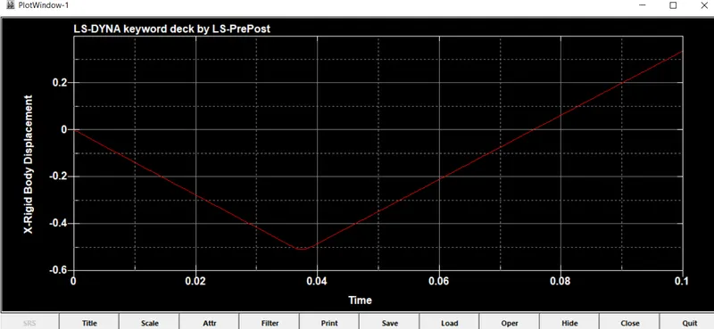
nodal accleration 1.5T
RESULT:
Thus a comparitive result between two sections are processed and displayed through graphs.
.