Week - 4 - Crash Box Simulation
AIM: To perform and create the rigid wall and crashing the rectangle box in rigid wall with basic file .k and from that obtaining the various simulation result and comparing with the variable thickness box such as 1.2mm and 1.5 mm with elastic material card.
MODEL SETUP: For this model they given maintain the gm,mm,ms unit system.
Base set up of Keywords
- Material creation
- Section creation
- Part definition
- Contact definition
- Velocity assign
- Control defination
- Output request(data base)
MATERIAL CREATION:
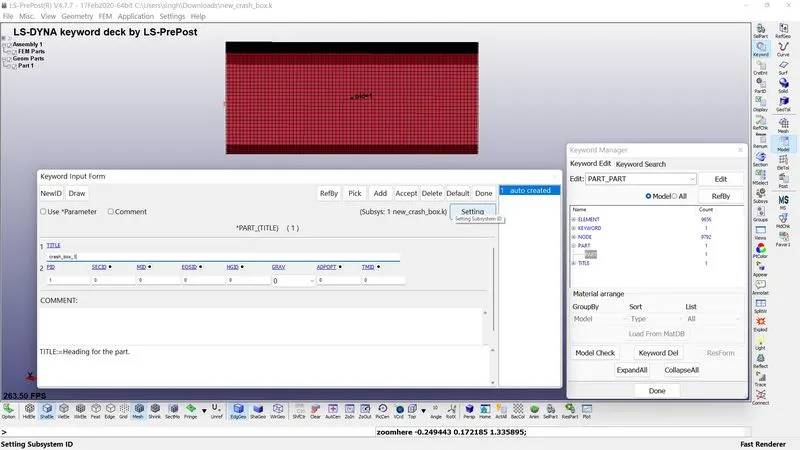
Before creating of the materials we check what are the parts list available to find that go to>model and part>part data. We has seen that it contain shell part as the name can change in crash_box_1here we consider the the box as made up of steel so, we take stell material property as-
MATERIAL PROPERTY OF STEEL
- DENSITY(Ro) 0.0078500
- YOUNG MODULUS 2.1E5
- POSSION RATIO(PR) 0.3
- YEILD STRESS(SIGN) 350
- TANGENT MODULAS(ETAN) 1E4
we need (rho,E,PR) to define the elastic material.
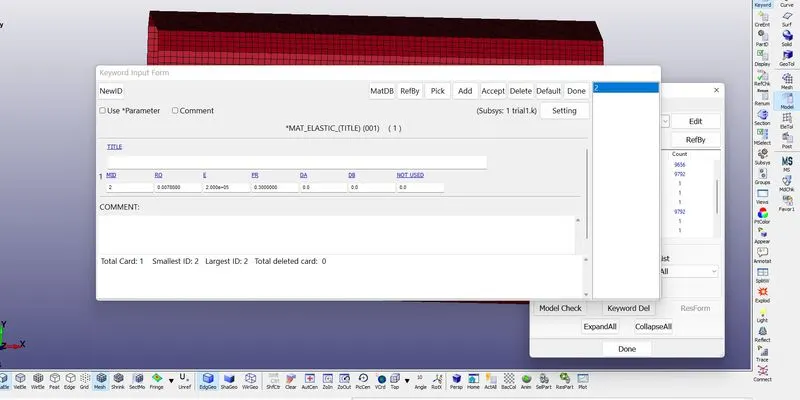
Here we consider the box material is 001_mat_elastic.
Section creation:
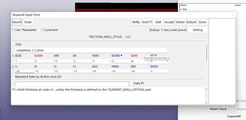
We know that the box as shell formulation so we assign the elform is 2 and the thickness=1.2mm.
Part definition:
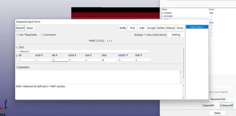
The created section and material are assigned to the box part.
Boundary setup:
For in this simualation we know that the box is hit higly strong rwall(rigid wall) so we want create a rigid wall in order to do that goto>create entity>rwall>create>planer>1n+NL
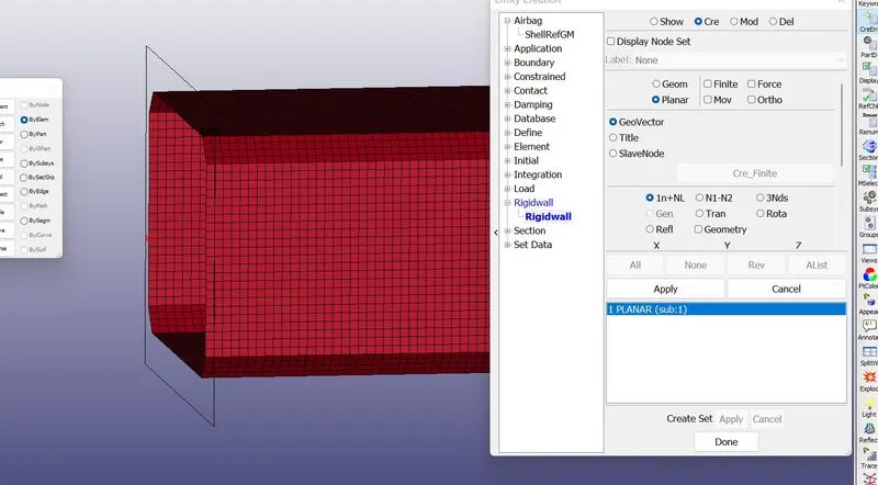
As the rwall is 30 mm away from the crash box.
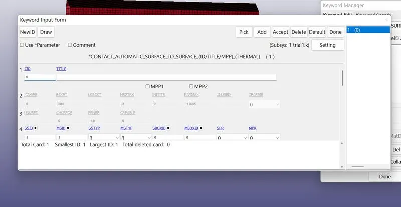
Contact definition: As we know the box is crashing the rwall so,there no contact penetration occur between the box and rwall so, we don't want create the contact defination for rwall but the box is contact himself so, we need to create the contact AUTOMATIC_SINGLE_SURF
VELOCITY ASSIGN(goto>create entity>Intial>velocity)
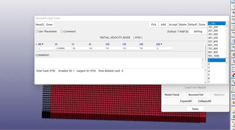
The box is moving the -13.88 mm/ms which include of gravitnational force also.
SECTION CREATION: We want the what is the force in middle of the crash box so that we want first create the SET_NODE and SET_ELEMENT in create entity and create sction from create_entity>database>cross_section.
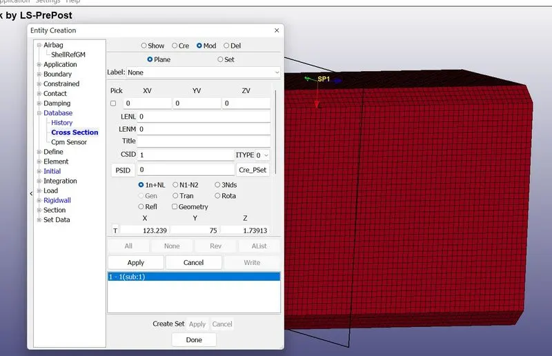
CONTROL TERMINATION:
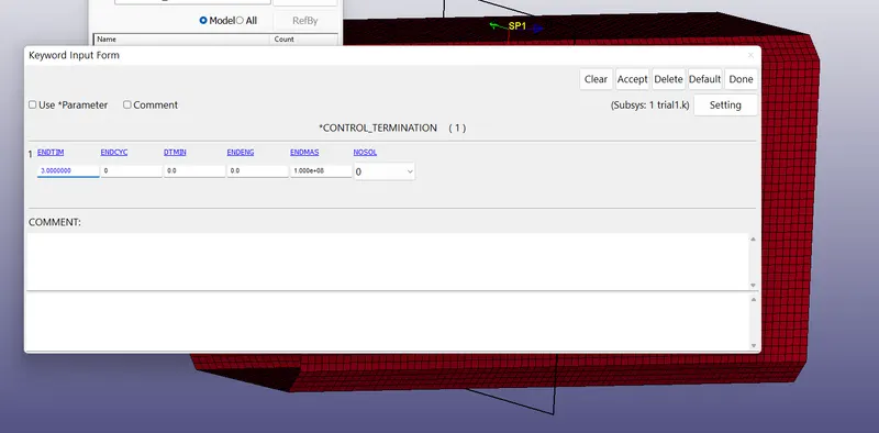
*control_hourglass=Redefine the default values of hourglass control type and coefficient. where ihq=1 is control the hour glass and qh=0.1
*control_termination =Stop the job. dt=3ms
Thses are the control cards are applied
OUTPUT REQUEST OR DATA BASE CARDS:
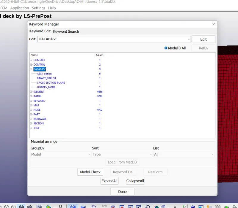
ASSCII
- SLEOUT
- RCFORC
- NODOUT
- MATSUM
- GLSTAT
- ELOUT
BINIARY_D3plot =This keyword is used to request binary output,Database for entire model.
CROSS_SECTION_SET - for visualation of output result at the particular section.
History node- for tracking the output data of the particular given node.
Post Processor:
case 1- THICKNESS 1.2mm
EFFECTIVE STRESS
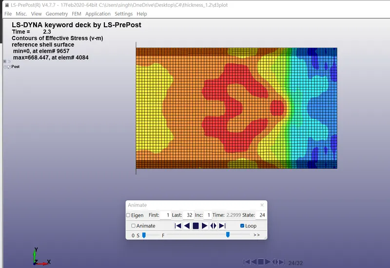
As we seen the image is effective von mises stress at time=2.3ms this the time step only the box hit to the rwall and that the wall resist the force so, there is some force is produce that is the stress the intial stress is very hig because the velcoity is high and the another reason is the with describe the effective stress in at time step int=3ms to see that whether the crashbox is penetrating the wall or not but it is observed that it bounces back and stress continously decreases and is disturbuted among the complete crashbox.
CASE-2 THICKNESS 1.5mm
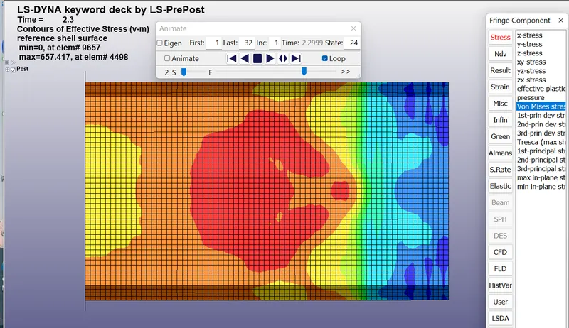
As we seen the image case -2 thickness 1.5mm with same material property but the thickness is varying the from 1.2 to 1.5 for that t=2.3 the stress is 657.147 but the t=1.2mm and time=2.3 ms the stress is=668.447 so, the thickness of 1.5mm box obtain the less stress as comparred to 1.2mm box.
CASE-1 THICKNESS 1.2mm-
EFFECTIVE STRAIN
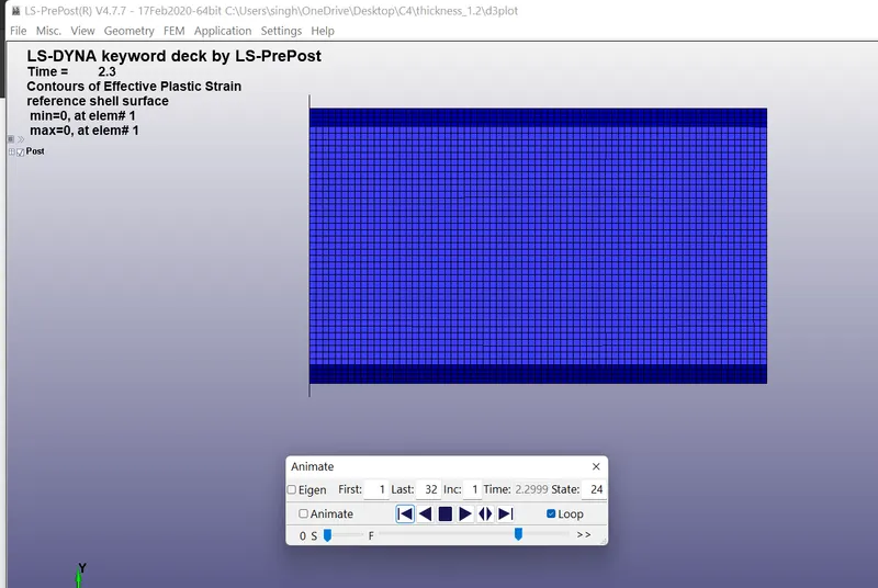
The strain is nothing but the changing length from above image we seen the box contact with the rwall with the time step t=2.3 ms at time the strain is 0.000 and the time step 3 and the strain is also 0 this happen because we have used the elastic model for our simulation purpose i.e why no plastic strain is developed.
CASE-2 THICKNESS 1.5 mm
EFFECTIVE STRAIN
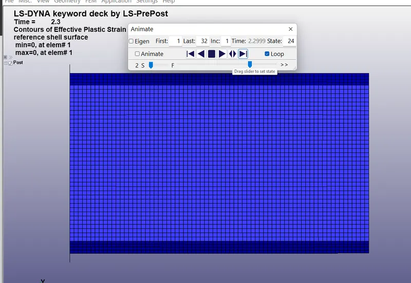
The strain is nothing but the changing length from above image we seen the box contact with the rwall with the time step t=2.3 ms at time the strain is 0.000 and the time step 3 and the strain is also 0 this happen because we have used the elastic model for our simulation purpose i.e why no plastic strain is developed.
CASE-1 KE, IE,TE,SE (thickness-1.2mm)
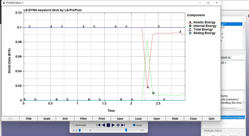
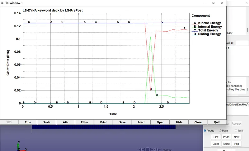
Internal energy is defined as the energy associated with the random, disordered motion of molecules. It is separated in scale from the macroscopic ordered energy associated with moving objects; it refers to the invisible microscopic energy on the atomic and molecular scale. As we seen the graph crash box IE and KE time 0 the energy also 0 which indicate there no energy dissipation between box and rwall but time 2.3 there is contact happening between the box and wall so, that the energy dissipation occur so, that internal energy of the box is increased after some time it come the more over constant i.e after impacting the box is bounce so the stress is evenly distrubuted around the box.
The kinetic energy (KE) of an object is the energy that it possesses due to its motion. It is defined as the work needed to accelerate a body of a given mass from rest to its stated velocity. Having gained this energy during its acceleration, the body maintains this kinetic energy unless its speed changes. in the same way but the energy dissipation happening for kinetic energy.
CASE-2 KE,IE,TE,SE(thickness-1.5mm)
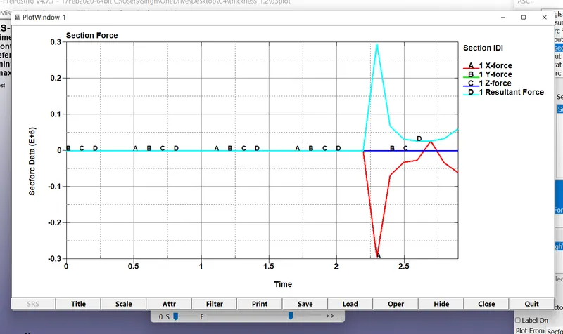
CASE-1 SECTION FORCE XYZ T=1.2mm
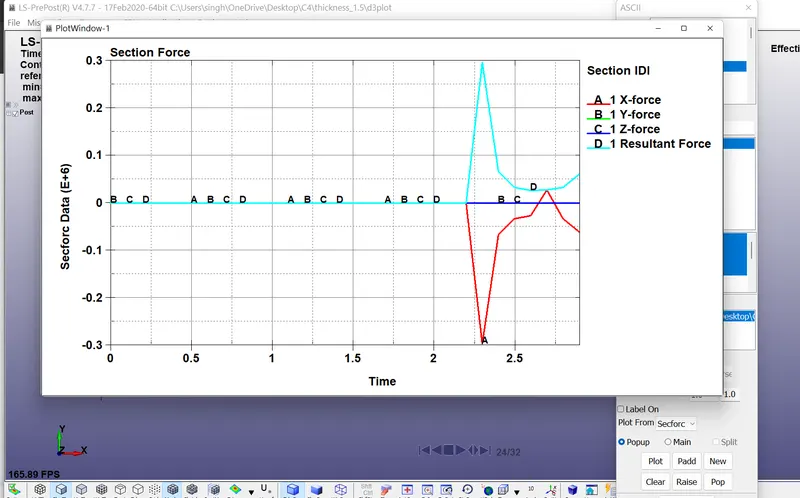
CASE-2 SECTION FORCE XYZ T=1.5mm
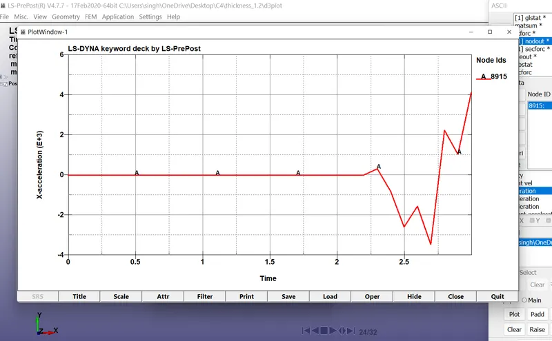
ACCLEARTION ALONG THE LENGTH DIRECTION AT 1.2mm
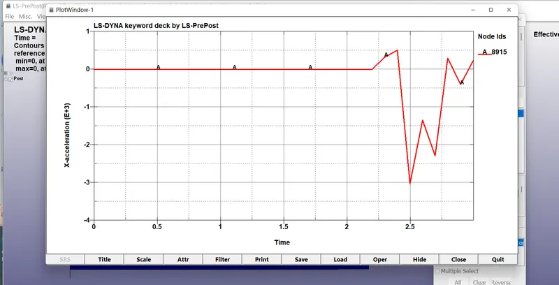
ACCLEARTION ALONG THE LENGTH DIRECTION AT 1.5mm
Result Comparison
for 1.2 mm
we have observed the below data.
1- Effective stress at 2.3 ms= 668.447Mpa.
2- Effective plastic strain =0.
3- Resultant Max force =3.0*10^5 N.
4- Accleration along X= -3.4 *10^-3m/s^2.
for 1.5 mm
1- Effective stress at 2.3 ms= 657.417Mpa.
2- Effective plastic strain =0.
3- Resultant Max force =3.0*10^5 N.
4- Accleration along X= -3.0 *10^-3m/s^2.
CONCULSION :
- As we seen the result comparison chart we decide in crash box having thickness 1.5mm have less stress, strain is same because we use elastic model, resultant force in both the cases is approximately same and in case of 1.5 mm box the retardation is also less.
- Through this assignment we learn the how to do the rwall and how give the property of contact.
- Through this assignment we learn the how apply the velocity, hourglass,control cards etc.
- Through this assignment we learned various type enegy dissipation curve .