Week 4 - CHT Analysis on Exhaust port
Give a brief description of why and where a CHT analysis is used.
The three main modes of heat transfer:
‐ Conduction is heat transfer that occurs when a temperature difference exists across a stationary medium.
‐ Convection is the heat transfer between a surface and a moving fluid when there is a temperature difference between the two.
‐ Radiation(thermal radiation) is the emission of energy in the form of electromagnetic waves. In the absence of an intervening medium ,there is net heat transfer by radiation between two surfaces at different temperatures.
Conjugate heat transfer is a type of heat transfer analysis between solids and fluid(s). This type of heat transfer includes both convection (between fluids) and conductive (between solids) heat transfer, as well as both forced and natural convection.
It allows for the simulation of heat transfer between solid and fluid domains by exchanging thermal energy at the interfaces between them. Typical applications of this analysis type exist as, but are not limited to, the simulation of heat exchangers, cooling of electronic equipment, and general-purpose cooling and heating systems.
Maintain the y+ value according to the turbulence model and justify the results.
Simulation:
Theory: Hot exhaust gases from the engine flows from the inner layer of the exhaust pipe and heat transfer takes place from the hot gases to the exhaust port and from the outer layer to the atmospheric air. thus the simulation can be done by assuming certain value of heat transfer coefficient for the outer exhaust pipe.
Setting up the geometry:
Open the Exhaust port cad file in the space claim.
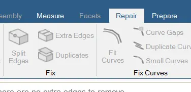
Select the edges but it does not allow to select due to the presence of the extra edges so go to Repair>extra edges>Select the xtra edges in red color>click on green tick.
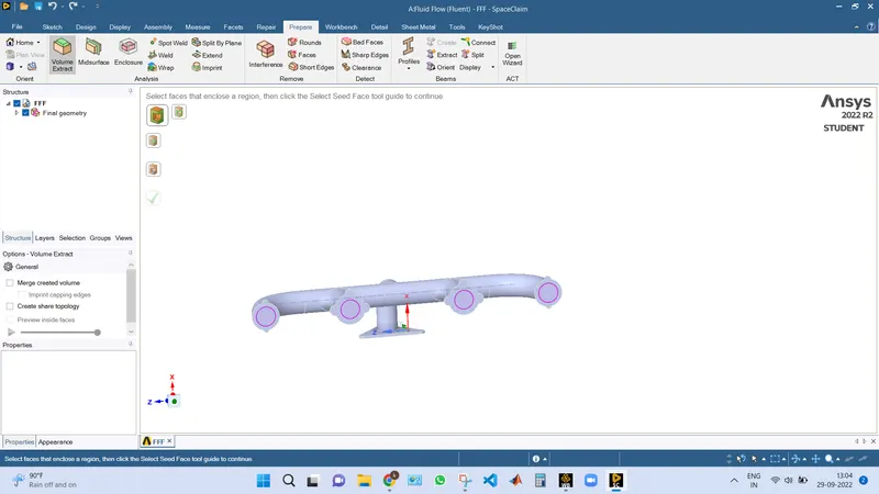
Go to prepare>volume extract option>select the edges>click on green tick option.
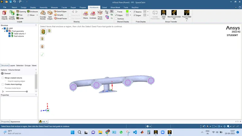
Now rename the selected volume as fluid volume and the other volume as solid volume.
Right click on design>delete empty components.
Share prep:
Now go to workbench>click on share>this creates share topology so that information is shared between the common boundaries otherwise it leads to non conformal mesh.
Meshing:
Create the named selections like inlet , outlet and boundarywall.
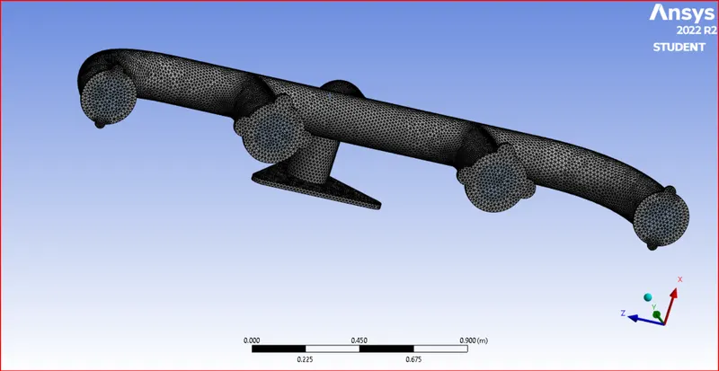
generate the mesh element size=0.015m(15 mm).
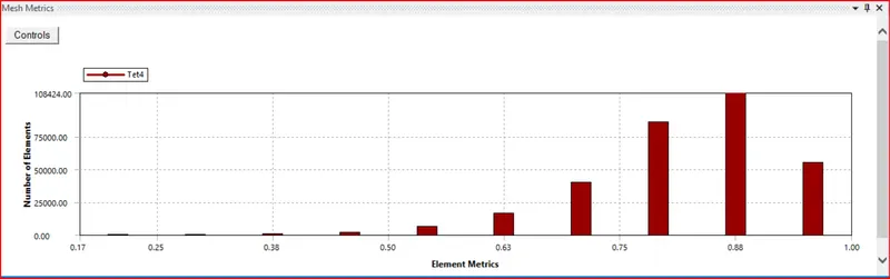
Mesh metrics:
No of cells:314473
Solver setup settings:
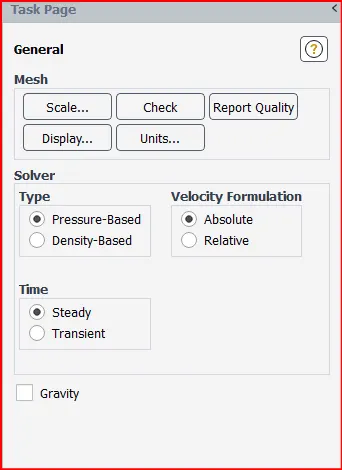
Select pressure based solver, absolute velocity and steady state simulation.
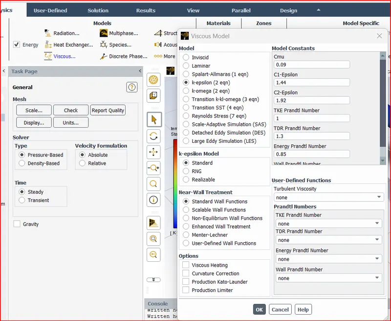
Select turbulent k-epsilon model
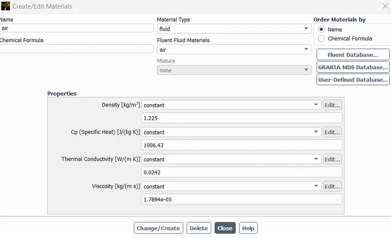
Select air for fluid and aluminium as solid.
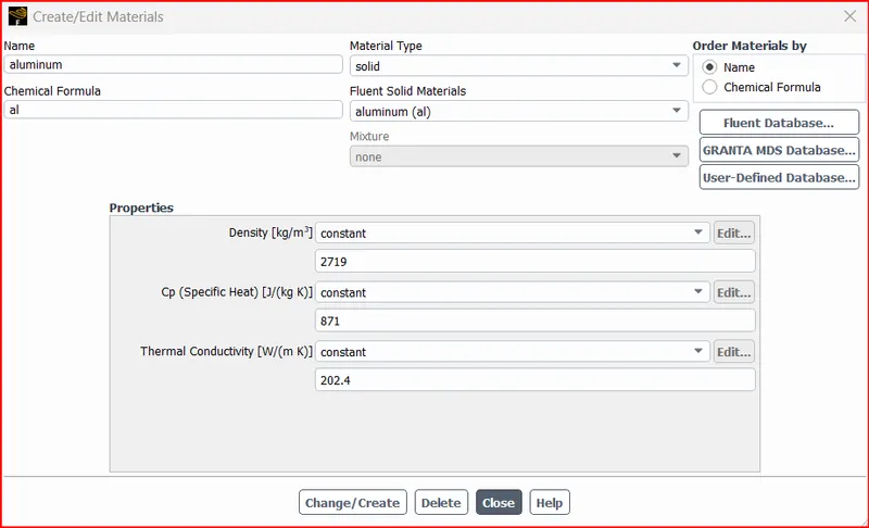
Set inlet vel to 5 m/s and temperature as 700K.
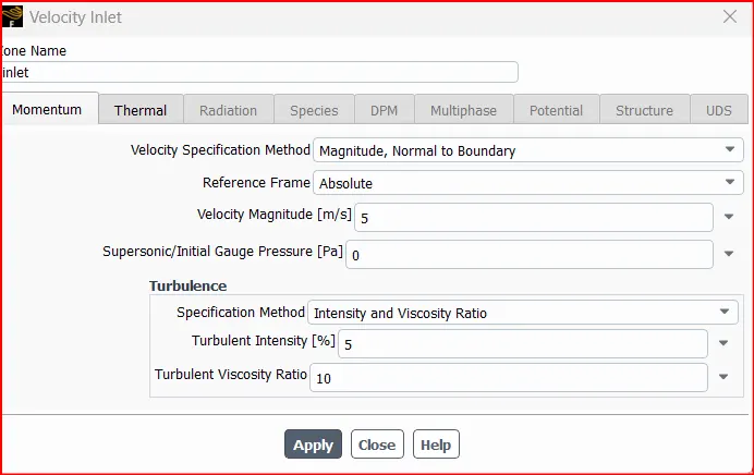
For outer wall ,
set heat transfer coeff as 20 w/m^2K
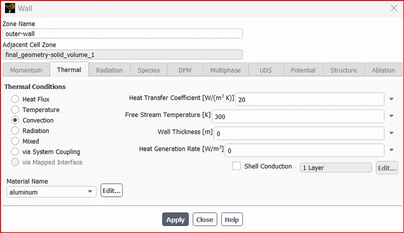
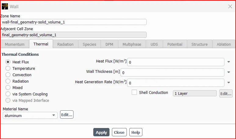
Initialize the setup and then setup contour plots as follows for temperature contour
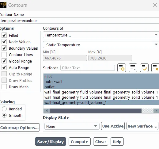
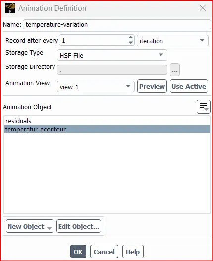
To create solution animation
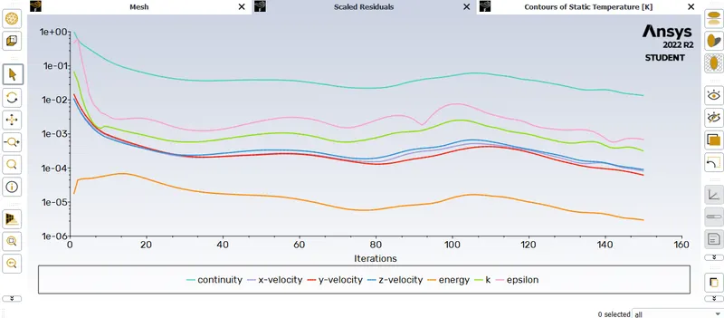
Residuals plot:
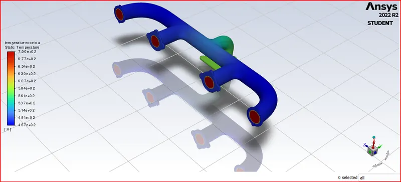
Contours of Temperature:
To export the simulation results to cfd post processing.
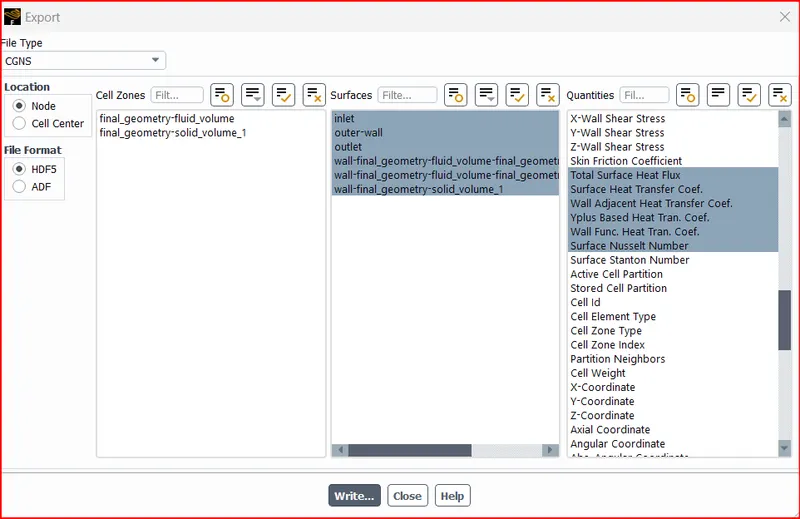
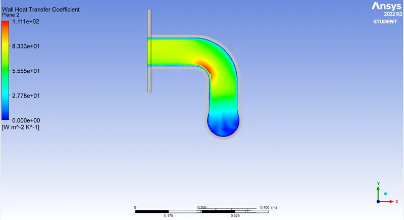
CFD post processing:
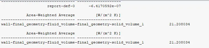
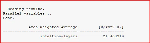
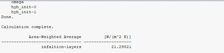
Wall heat transfer coefficient.
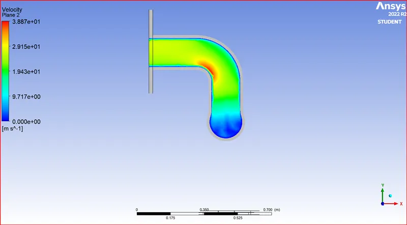
Velocity profile at the outlet port:
Case 2: Mesh Refinement
In this case we refine the mesh and check if it effects our results or not:
Mesh Refining:
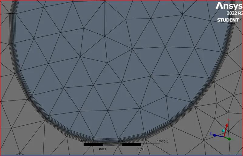
First we add Inflation layers around the inlet geometry so that the mesh around the curvature is smooth and replicate the geometry.
Then insert body sizing and use curvature capture option to generate a more refined mesh.
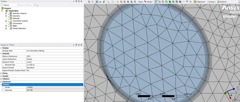
No. of elements: 327186
Solver settings:
Using the same solver settings as above we carry out the simulation.
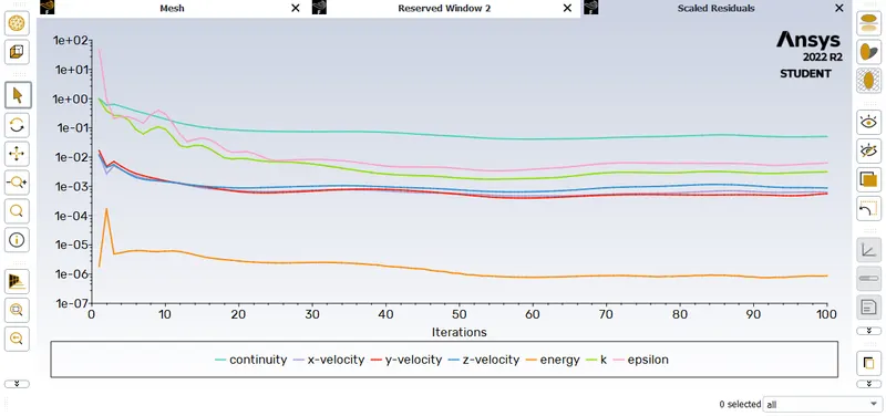
Residuals
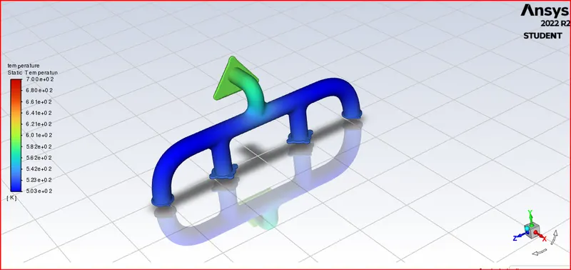
Temperature contour:
Case 3:
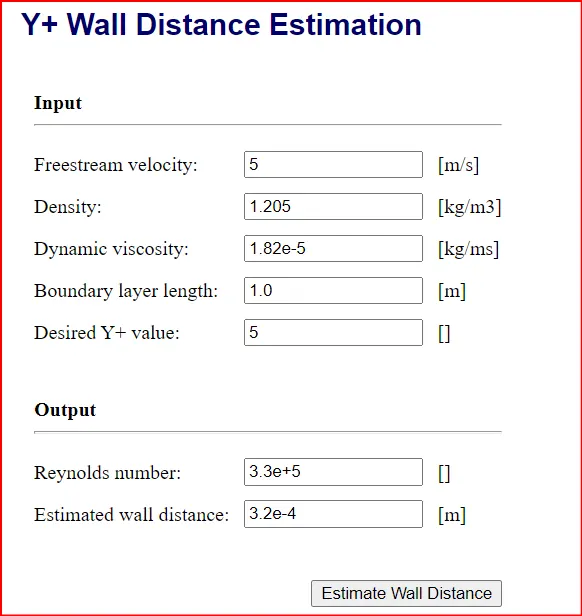
Refined mesh for k-w turbulent model with y+ value=5
Here y+ value is less than 10 so that all the laminar flow, buffer zone and log log flow region can be simulated.
and hence k-w turbulent model is used to solve the problem.
For this we calculate first layer thickness for the inflation layer using an online tool and then we mesh accordingly.
Solver settings:
select the k-w turbulent mdoel and run the simulation.
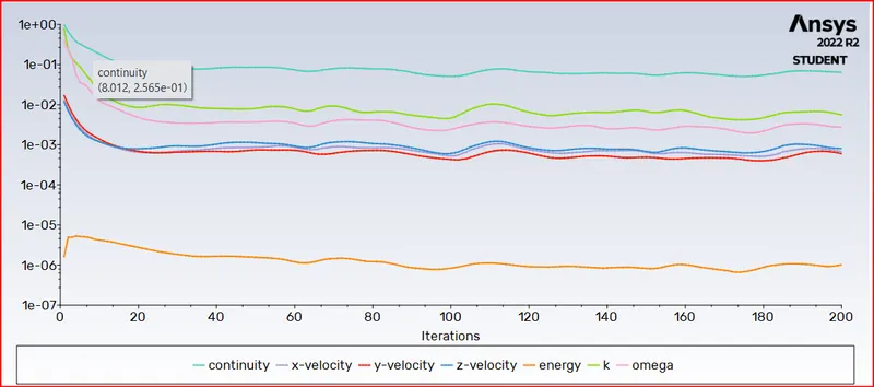
Residuals
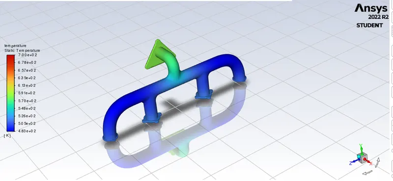
Temperature contour
velocity plot
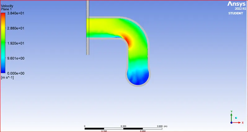
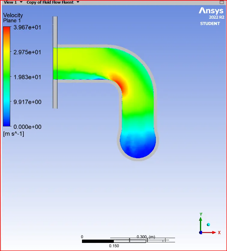
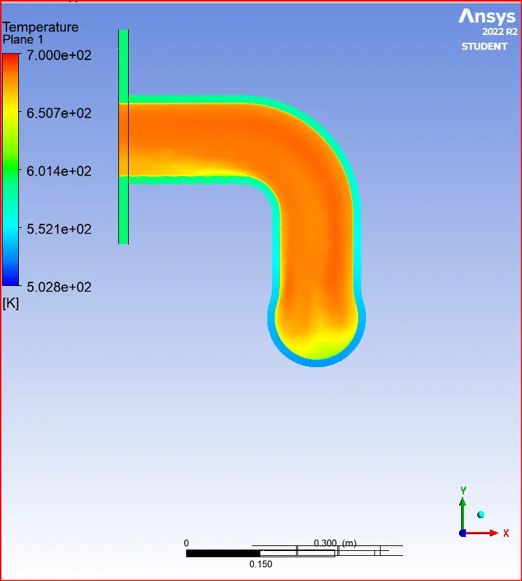
Calculate the wall/surface heat transfer coefficient on the internal solid surface & show the velocity & temperature contours in appropriate areas.
Case-1
No of cells:314473
Case-2
No of cells:327186
Case-3
How would you verify if the HTC predictions from the simulations are right? On what factors does the accuracy of the prediction depend on?
Heat transfer coefficient depend on the selecting the appropriate parameters during the simulation like the y+ values, appropriate turbulent model.
Ensure share topology is enabled to ensure proper flow of information beween the meshes.
Use of inflation layers give more appropriate results.
Conclusion:
Ensure share topology is enabled to ensure proper flow of information beween the meshes.
By refining the mesh quality, we get improved results from the simulation.
Use of inflation layers give more appropriate results.
selection of proper turbulent model is also necessary by calculating the appropriate y+ values.