Week 4 - CHT Analysis on Exhaust port
CHT Analysis on Exhaust port
Aim:- To do CHT(Conjugate Heat transfer) analysis by conducting simulation in Ansys and calculate the wall heat transfer coefficient on the internal solid surface and plotting velocity and temperature contours and validate all the predictions.
Introduction and Theory :-
Conjugate Heat Transfer :- Conjugate heat transfer corresponds with the combination of heat transfer in solids and heat transfer in fluids. In solids, conduction often dominates where as in fluids, convection usually dominates.For example, heat sinks are optimized to combine heat transfer by conduction in the heat sink with the convection in the surrounding fluid.Heat transfer in solids and heat transfer in fluids are combined in majority of the applications as the fluids always flow around the solids or between the solids.
CHT analysis :- The Conjugate Heat Transfer analysis is the simulation of heat transfer between solid and fluid domains by exchanging thermal energy at the interfaces between them.
- CHT analysis is used in processes which involve variations of temperature within solids and fluids,due to thermal interaction between the solids and fluids. The exchange of thermal energy between two physical bodies is called the Heat transfer.The rate of heat transfer is directly proportional to the temperature difference between the bodies.It is used in analyzing the heat transfer in a heat exchanger.A shell and tube heat exchanger is a perfect example of CHT,here one fluid flows through tubes and other fluid flows in the shell over the tubes.
- CHT analysis is used to control the cooling rate by predicting the heat transfer coefficient and to show the temperature variation of solid in various parts of it.CHT analysis is useful for predicting the heat transfer coefficient and to improve the effective heat transfer rate.It is also useful for analyzing the cooling of electronic devices.
- The CHT analysis is common in many engineering applications like heat exchangers,HVAC,electronic component design etc.
Nusselt number :- It is the ratio of convective to conductive heat transfer across a boundary.
Reynolds' number :- It is the ratio between the inertial forces to the viscous forces.Generally Reynolds' number describes the type of flow of the fluid.
Prandtl number :- It is the ratio of the momentum diffusivity to the thermal diffusivity.
Heat transfer coefficient :- The heat transfer coefficient is the proportionality constant between the heat flux and the thermodynamic driving force for the flow of heat.It is the reciprocal of thermal insulance.It is often calculated from the Nusselt number.Units(W/m^2.K)
Geometry :-
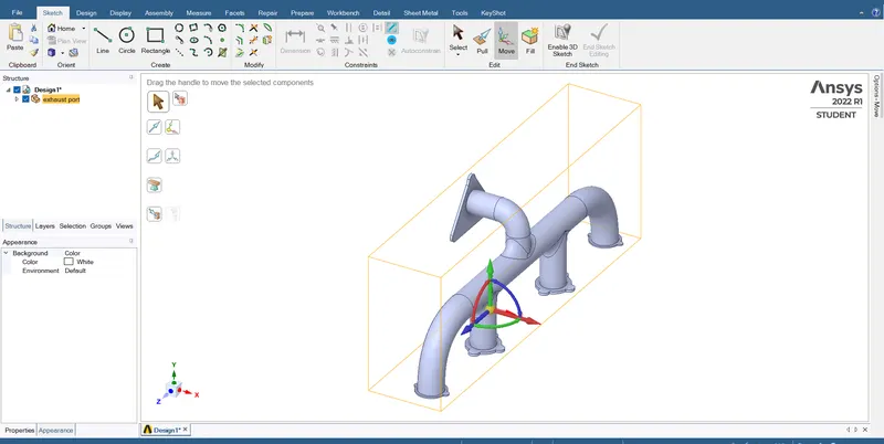
- We have imported the exhaust port model to the spaceclaim of workbench.
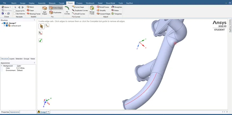
- Go to 'Repair' section and remove the extra edges which are present on the exhaust port model.
- Select 'Extra Edges' option and then spaceclaim will show us the extra edges in red colour.We can select those edges and then spaceclaim will remove those edges,this is manual mehod and also by just clicking on the green coloured tick mark we can remove all the extra edges automatically(this automatic method is useful for complex shapes).
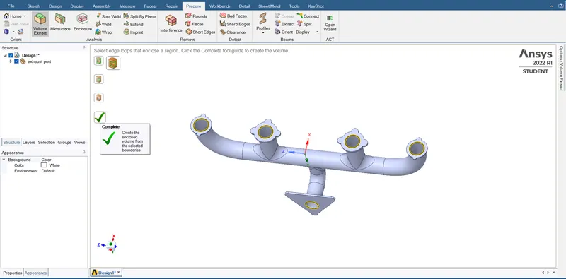
- For CHT analysis we have to fill the exhaust pipe with the fluid inside it.
- We go to 'Prepare' and choose edge selection method and select the edges that enclose the region.(4 inlet edges & 1 outlet edge)
- Click on 'complete' to create the volume.
- Now if we proceed for meshing then we can see that the solid and fluid interfaces are not perfectly alligned.
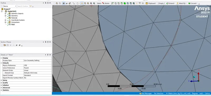
- To avoid these spacing we have to share topology in Geometry.We go back to spaceclaim and fix this.
- After the fluid is filled inside,we use 'share' option in the workbench to make sure that there are no gaps between the solid and fluid interfaces.There should not be any physical distance between the solid and fluid.(perfect interfacing).
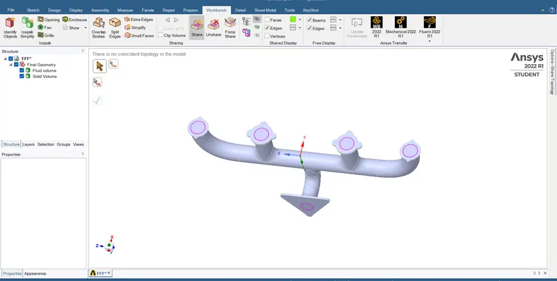
- Now again if we go for Meshing in CFD pre-post we can see that there are no spaces between solid and fluid interfaces.
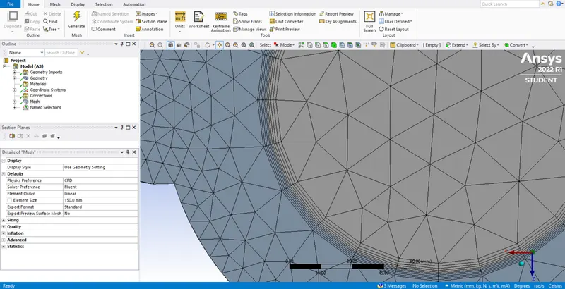
Meshing :-
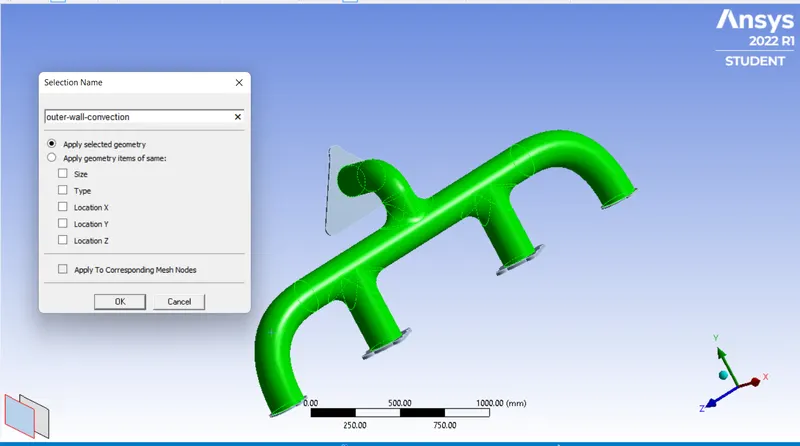
- After refining the geometry now we have to give the namings for all the parts of the exhaust port model.
- Named Selections :- Inlets,Outlet,Outer wall convection.
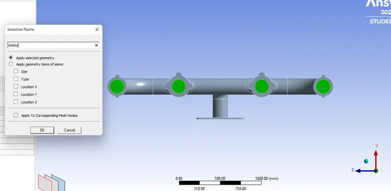
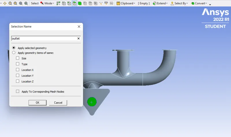
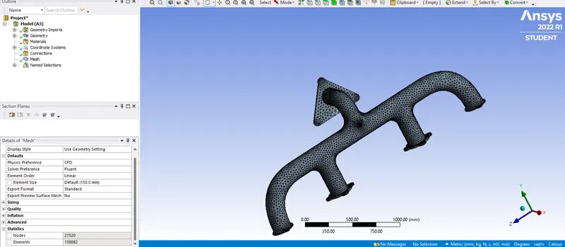
- Now click on Generate mesh and check the statistics for nodes and elements.
- Nodes = 27520, Elements = 138062 . Max limit is half a million so we can minimize element size for some parts.
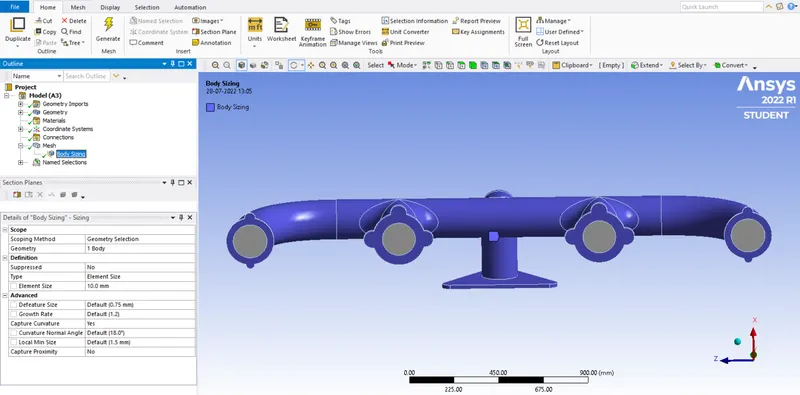
- Insert Body sizing method and select the solid body and reduce the element size to 10mm and generate the mesh.
Inflation :-
Maintaining the y+ value according to the turbulence model :-
value of y+ is taken in range of 0<y+<5 . We take k-omega turbulence model since we study near the wall.(since we want surface wall heat transfer coefficient)
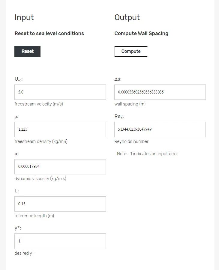
Height of the first inflation layer is two times of △s since it is the distance from centre to boundary wall.
△s = 0.0556mm so the first layer thickness = 0.12mm (approx)
- Add Inflation layers with a first layer height of 0.12mm,growth rate 1.2 and maximum no.of layers =5. Generate mesh.
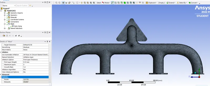
- Now the statistics are Nodes = 121778,Elements = 352067.(finer mesh and within the cells limit)
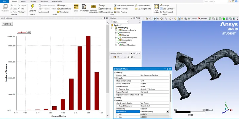
- Quality of the mesh :-
Setup:-
- We are using steady state solver to run the simulation and a pressure based solver since mach number is less than 0.3
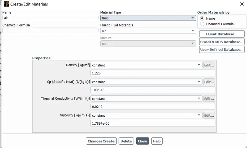
- Mach number = Fluid velocity at inlet/speed of sound = 5/344 = 0.014 (< 0.3).So we use a pressure based solver since it is an incompressible flow,Dynamic viscosity(μ) = 0.012056kg/m-s, Density of fluid(ρ) = 1.225kg/m^3.
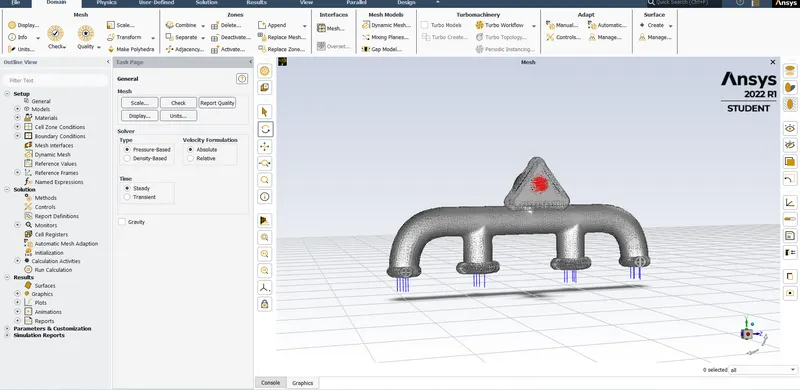
- Absolute velocity formulation is selected and also we use the energy equation as we want to know about the temperature variation and wall heat transfer coefficients.Also we use k-omega model since we study near the wall.
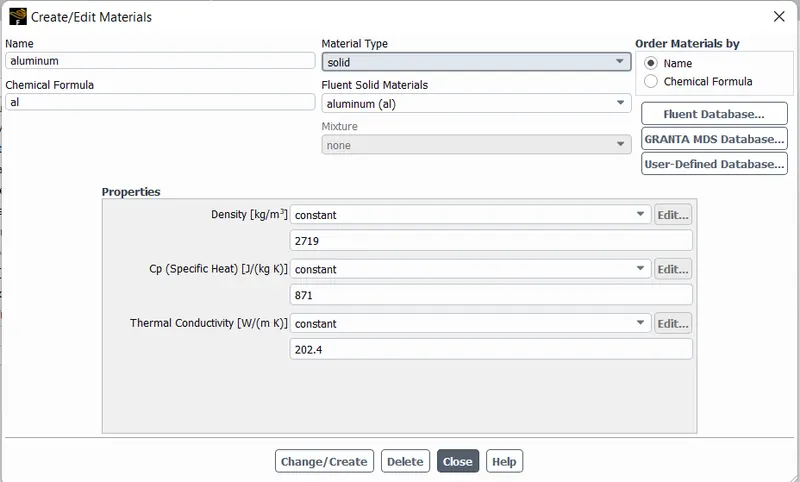
- Materials :- Fluid - air , Solid - Alluminium ( also we can change the required solids and fluids from the Ansys Fluent
- Boundary conditions :- Inlets' velocity = 5m/s, outlet is a pressure outlet with 0 guage pressure and the outer convection wall is with a heat transfer coefficient of 20 [W/(m^2).K].Ansys fluent will consider the remaining walls as adiabatic.
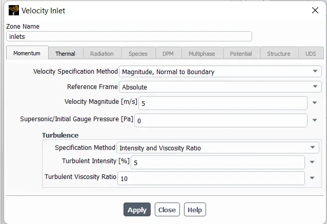
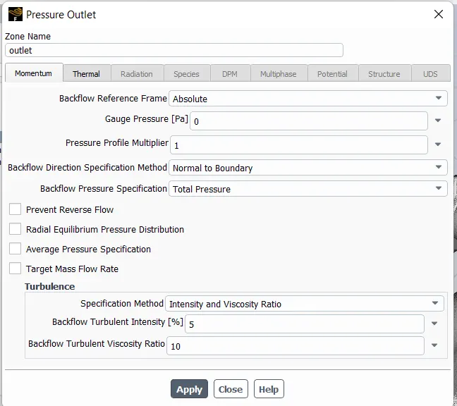
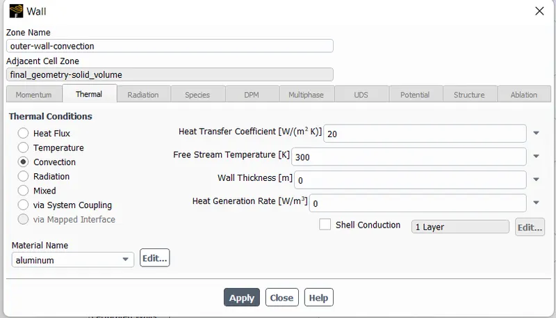
- Select hybrid initialization method and initialize the solution and then run the solution for 150 iterations
Results:-
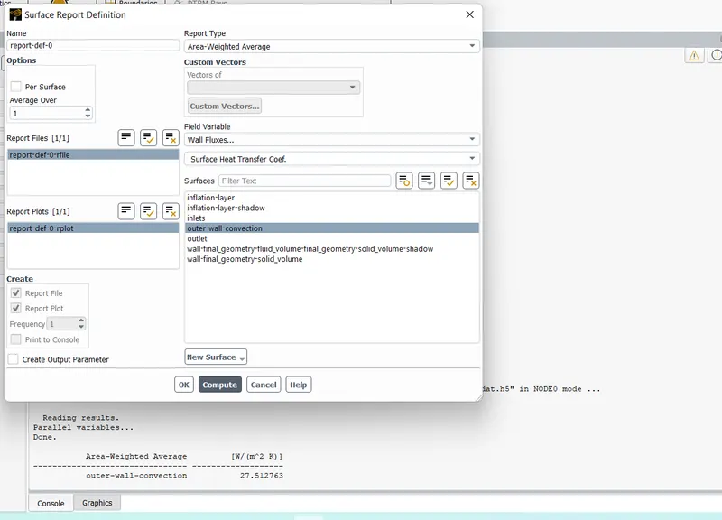
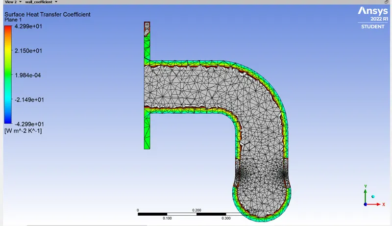
Area weighted average of Heat transfer coefficient :-
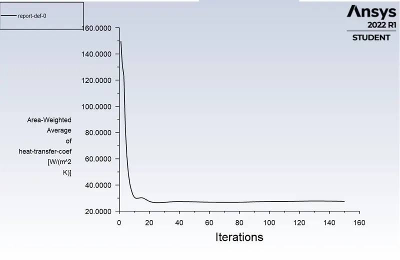
The solution we obtained for the value of Heat transfer coefficient is 27.512763 (W/m^2.K)
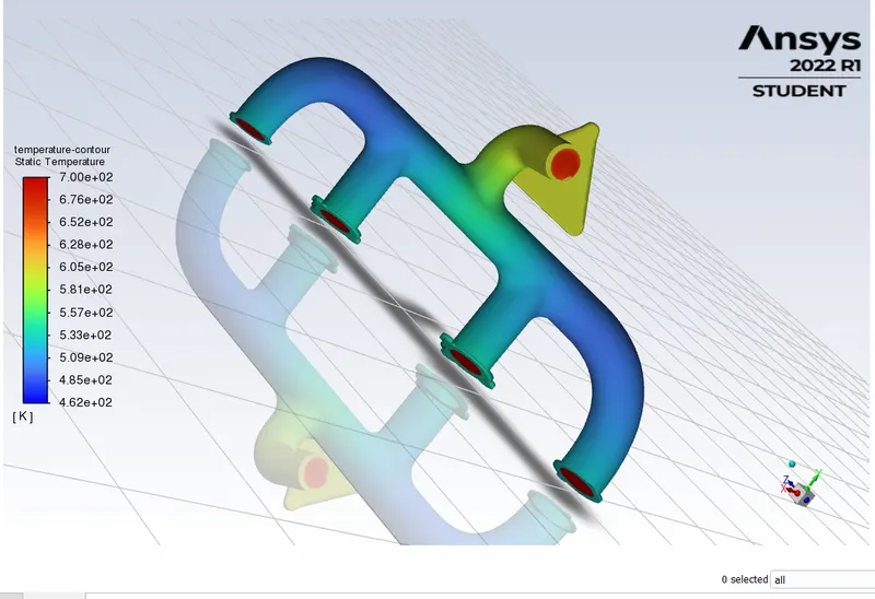
Temperature contour :-
Velocity plot in CFD :-
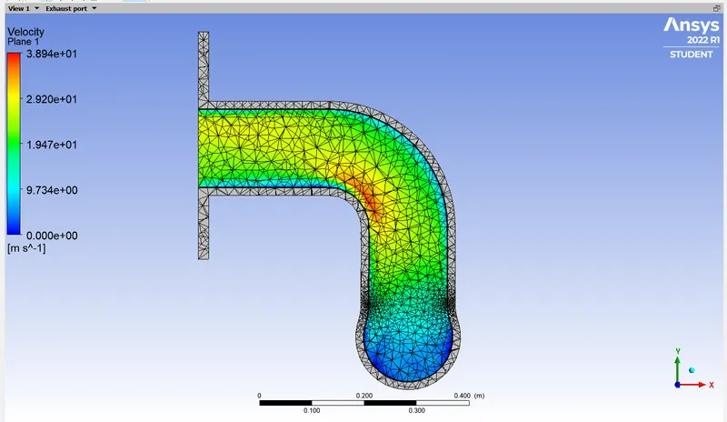
Velocity streamline :- (Including temperature along the outer convection wall)
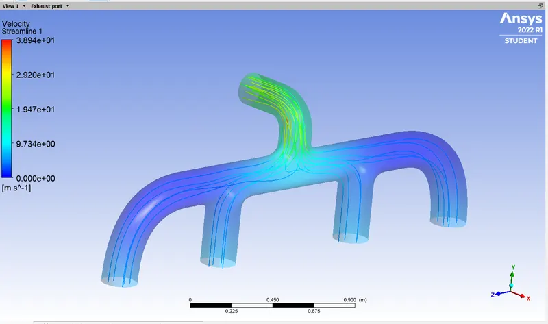
From this we can observe that both velocity and temperature increases from inlets to outlet.
Temperature contour in CFD :-
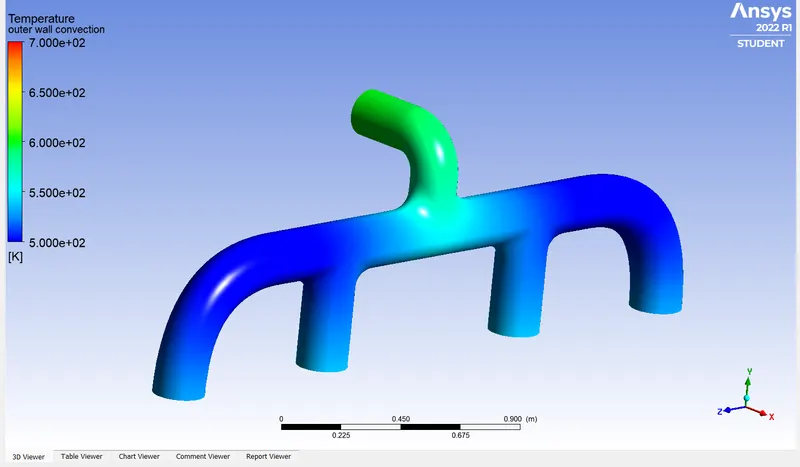
Surface Heat transfer coefficient :-
Analytical solution for Heat transfer coefficient :- Nu = h.L/k from this formula we get h = Nu.k/L where Nu = Nusselt number, h = heat transfer coefficient in W/m^2.K, L =characteristic length in m, k = Thermal conductivity in W/m.K.
Nu = 0.332*(Re^0.5)*(Pr^0.33) [We use this formula since it is a forced convection heat transfer process]
Prandtl number = Pr = μ/ρ.alpha where 'alpha' is thermal diffusivity of air.
μ = 0.012056kg/m.s
ρ = 1.225 kg/m^3
alpha = 1.9*10^(-5) m^2/s
k = 0.0242 W/m.K
By substituting all these values we get 'h' = 21.38W/m^2.K
The Numerical solution we obtained from the simulation is 27.51W/m^2.K and the error percentage is less.Hence the Heat transfer coefficient predictions from the simulations are correct.
Conclusion :-
- In this project we have done CHT analysis on an exhaust port and we predicted heat transfer coefficients and temperatures at various points.
- Also we plot velocity and temperature contours to visualize the fluid path.
- From the above study we can notice that the heat transfer coefficient value at walls and bends is higher.
- Factors affecting the Heat Transfer coefficient prediction are :-
1) Element size and quality - Finer the mesh,accurate will be the results.
2) Velocity - By increasing the velocity at the inlets we can get higher 'h' value
3) Inflational layer - It increases the quality of the mesh near the boundary.
4) Meshing at the solid-fluid interface.