Week-4 Challenge WOT Condition Part-2
- What is the difference between mapped and dynamic model of engine, motor and generator? How can you change model type?
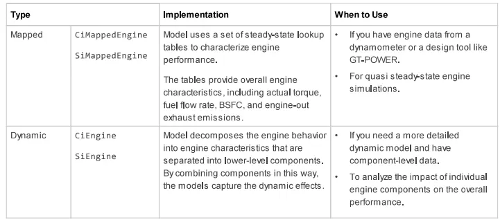
A. Difference between mapped and dynamic models was briefed in the table below:For reference a engine is taken.
- From the table we can infer that the mapped models are the models that use look up table with the data collected from simulations are practical working of model(engine),whereas the dynamic models are those which are constructed using lower level components to simulate the behaviour of model (engine).
Internal Combustion Mapped and Dynamic Engine Models
When you customize a SI or CI reference application, you can use either a dynamic or mapped engine model. The table provides considerations for using either implementation.
Mapped CI Engine
Compression-ignition engine model using lookup tables
- Library:
-
Powertrain Blockset / Propulsion
Vehicle Dynamics Blockset / Powertrain
Description
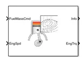
The Mapped CI Engine block implements a mapped compression-ignition (CI) engine model using power, air mass flow, fuel flow, exhaust temperature, efficiency, and emission performance lookup tables. You can use the block for:
-
Hardware-in-the-loop (HIL) engine control design
-
Vehicle-level fuel economy and performance simulations
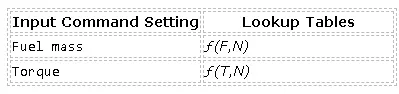
The lookup tables, developed with the Model-Based Calibration Toolbox™, are functions of either injected fuel mass, F, or engine torque, T, and engine speed, N.
The block enables you to specify lookup tables for these engine characteristics:
-
Power
-
Air
-
Fuel
-
Temperature
-
Efficiency
-
Hydrocarbon (HC) emissions
-
Carbon monoxide (CO) emissions
-
Nitric oxide and nitrogen dioxide (NOx) emissions
-
Carbon dioxide (CO2) emissions
-
Particulate matter (PM) emissions
If you have Model-Based Calibration Toolbox, click Calibrate Maps to virtually calibrate the lookup tables using measured data.
To bound the Mapped CI Engine block output, the block does not extrapolate the lookup table data.
Cylinder Air Mass
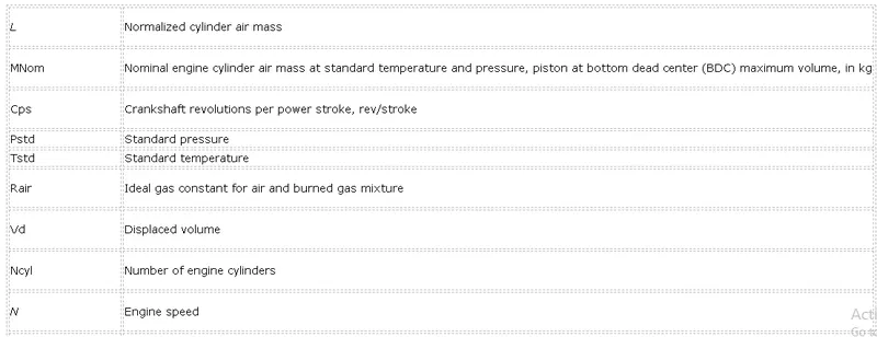
The block calculates the normalized cylinder air mass using these equations.
MNom=PstdVdNcylRairTstdL=(60smin)Cps⋅˙mair(1000gKg)Ncyl⋅N⋅MNom
The equations use these variables.
Turbocharger Lag
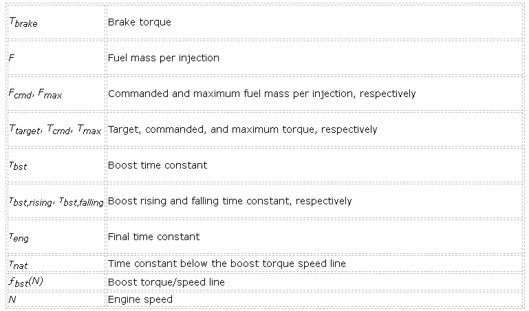
To model turbocharger lag, select Include turbocharger lag effect. Turbocharger lag limits the maximum fuel mass per injection. To model the maximum fuel mass per injection, the block uses a first-order system with a time constant. At low torque, the engine does not require boost to provide sufficient air flow. When the requested fuel mass requires boost, the block uses a time constant to determine the maximum fuel mass per injection. The block uses these equations for the specified Input command setting.
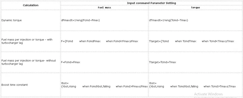
The equations use these variables.
Ports
Input
FuelMassCmd — Injected fuel mass command
scalar
Injected fuel mass command, F, in mg/inj.
Dependencies
To create this port, for Input command, select Fuel mass.
TrqCmd — Torque command
scalar
Torque command, T, in N·m.
Dependencies
To create this port, for Input command, select Torque.
EngSpd — Engine speed
scalar
Engine speed, N, in rpm.
Output
Input command — Table functions
Fuel mass (default) | Torque
The lookup tables, developed with the Model-Based Calibration Toolbox, are functions of either injected fuel mass, F, or engine torque, T, and engine speed, N.
Dependencies
-
Selecting
Fuel massenables Breakpoints for commanded fuel mass input, f_tbrake_f_bpt. -
Selecting
Torqueenables Breakpoints for commanded torque input, f_tbrake_t_bpt.
Include turbocharger lag effect — Increase time constant
off (default)
To model turbocharger lag, select Include turbocharger lag effect. Turbocharger lag limits the maximum fuel mass per injection. To model the maximum fuel mass per injection, the block uses a first-order system with a time constant. At low torque, the engine does not require boost to provide sufficient air flow. When the requested fuel mass requires boost, the block uses a time constant to determine the maximum fuel mass per injection. The block uses these equations for the specified Input command setting.
Dependencies
Selecting Include turbocharger lag effect enables these parameters:
-
Boost torque line, f_tbrake_bst
-
Time constant below boost line, tau_nat
-
Rising maximum fuel mass boost time constant, tau_bst_rising
-
Falling maximum fuel mass boost time constant, tau_bst_falling
CI Core Engine
-
Powertrain Blockset / Propulsion / Combustion Engine Components

Description
The CI Core Engine block implements a compression-ignition (CI) engine from intake to the exhaust port. You can use the block for hardware-in-the-loop (HIL) engine control design or vehicle-level fuel economy and performance simulations.
The CI Core Engine block calculates:
-
Brake torque
-
Exhaust temperature
-
Air-fuel ratio (AFR)
-
Fuel rail pressure
-
-
Hydrocarbon (HC)
-
Carbon monoxide (CO)
-
Nitric oxide and nitrogen dioxide (NOx)
-
Carbon dioxide (CO2)
-
Particulate matter (PM)
Engine-out (EO) exhaust emissions:
-
Air Mass Flow
To calculate the air mass flow, the compression-ignition (CI) engine uses the CI Engine Speed-Density Air Mass Flow Model. The speed-density model uses the speed-density equation to calculate the engine air mass flow, relating the engine intake port mass flow to the intake manifold pressure, intake manifold temperature, and engine speed.
Brake Torque
To calculate the engine torque, you can configure the block to use either of these torque models.
SI Core Engine
Spark-ignition engine from intake to exhaust port
- Library:
-
Powertrain Blockset / Propulsion / Combustion Engine Components
Description
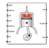
The SI Core Engine block implements a spark-ignition (SI) engine from intake to exhaust port. You can use the block in larger vehicle models, hardware-in-the-loop (HIL) engine control design, or vehicle-level fuel economy and performance simulations.
The SI Core Engine block calculates:
-
Brake torque
-
Fuel flow
-
Port gas mass flow, including exhaust gas recirculation (EGR)
-
Air-fuel ratio (AFR)
-
Exhaust temperature and exhaust mass flow rate
-
-
Hydrocarbon (HC)
-
Carbon monoxide (CO)
-
Nitric oxide and nitrogen dioxide (NOx)
-
Carbon dioxide (CO2)
-
Particulate matter (PM)
Engine-out (EO) exhaust emissions
-
Mapped SI Engine
Spark-ignition engine model using lookup tables
- Library:
-
Powertrain Blockset / Propulsion
Vehicle Dynamics Blockset / Powertrain
Description
The Mapped SI Engine block implements a mapped spark-ignition (SI) engine model using power, air mass flow, fuel flow, exhaust temperature, efficiency, and emission performance lookup tables. You can use the block for:
-
Hardware-in-the-loop (HIL) engine control design
-
Vehicle-level fuel economy and performance simulations
The block enables you to specify lookup tables for these engine characteristics. The lookup tables, developed with the Model-Based Calibration Toolbox™, are functions of commanded torque, Tcmd, brake torque, Tbrake, and engine speed, N.
-
Power — ƒ(Tcmd,N)
-
Air — ƒ(Tbrake,N)
-
Fuel — ƒ(Tbrake,N)
-
Temperature — ƒ(Tbrake,N)
-
Efficiency — ƒ(Tbrake,N)
-
Hydrocarbon (HC) emissions — ƒ(Tbrake,N)
-
Carbon monoxide (CO) emissions — ƒ(Tbrake,N)
-
Nitric oxide and nitrogen dioxide (NOx) emissions — ƒ(Tbrake,N)
-
Carbon dioxide (CO2) emissions — ƒ(Tbrake,N)
-
Particulate matter (PM) emissions — ƒ(Tbrake,N)
If you have Model-Based Calibration Toolbox, click Calibrate Maps to virtually calibrate the lookup tables using measured data.
To bound the Mapped SI Engine block output, the block does not extrapolate the lookup table data.
Mapped Motor
Mapped motor and drive electronics operating in torque-control mode
- Library:
-
Powertrain Blockset / Propulsion Vehicle Dynamics Blockset / Powertrain
Description
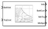
The Mapped Motor block implements a mapped motor and drive electronics operating in torque-control mode. The output torque tracks the torque reference demand and includes amotor-response and drive-response time constant. Use the block for fast system-level simulations when you do not know detailed motor parameters, for example, for motor power and torque tradeoff studies. The block assumes that the speed fluctuations due to mechanical load do not affect the motor torque tracking.
You can specify:
-
Port configuration — Input torque or speed
-
Electrical torque range — Torque speed envelope or maximum motor power and torque
-
Electrical loss — Single operating point, measured efficiency, or measured loss
Induction Motor
Three-phase induction motor
- Library:
-
Powertrain Blockset / Propulsion / Electric Motors / Fundamental Flow
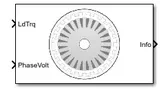
Description
The Induction Motor block implements a three-phase induction motor. The block uses the three-phase input voltages to regulate the individual phase currents, allowing control of the motor torque or speed.
Three-Phase Sinusoidal Model Electrical System
The block implements equations that are expressed in a stationary rotor reference (qd) frame. The d-axis aligns with the a-axis. All quantities in the rotor reference frame are referred to the stator.
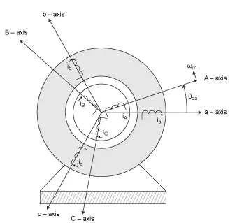
The block uses these equations to calculate the electrical speed (ωem) and slip speed (ωslip).
ωem=Pωmωslip= ωsyn−ωem
To calculate the dq rotor electrical speed with respect to the rotor A-axis (dA), the block uses the difference between the stator a-axis (da) speed and slip speed:
ωdA= ωda− ωem
To simplify the equations for the flux, voltage, and current transformations, the block uses a stationary reference frame:
ωda=0ωdA=−ωem
Wind Turbine Induction Generator (Phasor Type)
Implement phasor model of squirrel-cage induction generator driven by variable pitch wind turbine
Library
Simscape / Electrical / Specialized Power Systems / Renewables / Wind Generation

Description
The wind turbine and the induction generator (WTIG) are shown below. The stator winding is connected directly to the grid and the rotor is driven by the wind turbine. The power captured by the wind turbine is converted into electrical power by the induction generator and is transmitted to the grid by the stator winding. The pitch angle is controlled in order to limit the generator output power to its nominal value for high wind speeds. In order to generate power the induction generator speed must be slightly above the synchronous speed. But the speed variation is typically so small that the WTIG is considered to be a fixed-speed wind generator. The reactive power absorbed by the induction generator is provided by the grid or by some devices like capacitor banks, SVC, STATCOM, or synchronous condenser.
Pitch Angle Control System
The wind turbine model uses the Wind Turbine block of the Renewables/Wind Generation library. See documentation of this block for details.
A Proportional-Integral (PI) controller is used to control the blade pitch angle in order to limit the electric output power to the nominal mechanical power. The pitch angle is kept constant at zero degrees when the measured electric output power is under its nominal value. When it increases above its nominal value, the PI controller increases the pitch angle to bring back the measured power to its nominal value.
Parameters
The WTIG parameters are grouped in two categories: Generator data and Turbine data». Use the Display listbox to select which group of parameters you want to visualize.
Generator Tab
- External turbine (Tm mechanical torque input)
-
When this parameter is selected, the Turbine tab is not visible in the mask dialog box, and a Simulink® input named Tm appears on the block, allowing to use an external signal for the generator input mechanical torque. This external torque must be in pu based on the nominal electric power and synchronous speed of the generator. For example, the external torque may come from a user defined turbine model. By convention for the induction machine, the torque must be negative for power generation. Default is cleared.
- Nominal power, line-to-line voltage and frequency
-
The nominal power in VA, the nominal line-to-line voltage in Vrms and the nominal system frequency in hertz. Default is
[1.5e6/0.9, 575, 60]. - Stator [Rs, Lls]
-
The stator resistance Rs and leakage inductance Lls in pu based on the generator ratings. Default is
[ 0.004843, 0.1248]. - Rotor [Rr', Llr']
-
The rotor resistance Rr' and leakage inductance Llr', both referred to the stator, in pu based on the generator ratings. Default is
[ 0.004377, 0.1791]. - Magnetizing inductance Lm
-
The magnetizing inductance Lm in pu based on the generator ratings. Default is
6.77. - Inertia constant, friction factor and pairs of poles
-
Combined generator and turbine inertia constant H in seconds, combined viscous friction factor F in pu based on the generator ratings and number of pole pairs p. Default is
[5.04, 0.01, 3].You may need to use your own turbine model, in order for example, to implement different power characteristics or to implement the shaft stiffness. Your model must then output the mechanical torque applied to the generator shaft. If the inertia and the friction factor of the turbine are implemented inside the turbine model you specify only the generatorinertia constant H and the generator friction factor F.
- Initial conditions
-
The initial slip s, electrical angle Θ in degrees, stator current magnitude in pu and phase angle in degrees. Default is
[ -0.01,0, 0,0,0, 0,0,0 ].
Turbine Tab
This tab is not visible when the External turbine (Tm mechanical torque input) parameter is selected.
Refer to the Wind Turbine for detailed documentation.
- Pitch angle beta used to display characteristics (beta >= 0)
-
Specify the pitch angle used to display the wind turbine power characteristics. Default is
0. - Nominal wind turbine mechanical output power
-
This parameter is not visible when the External turbine (Tm mechanical torque input) parameter is selected.
The nominal turbine mechanical output power in watts. Default is
1.5e6. - Base wind speed
-
This parameter is not visible when the External turbine (Tm mechanical torque input) parameter is selected.
The base value of the wind speed, in m/s, used in the per unit system. The base wind speed is the mean value of the expected wind speed. This base wind speed produces a mechanical power which is usually lower than the turbine nominal power. Default is
9. - Base rotational speed
-
This parameter is not visible when the External turbine (Tm mechanical torque input) parameter is selected.
The rotational speed at maximum power for the base wind speed. The base rotational speed is in pu of the base generator speed. Default is
1. - Maximum power at base wind speed
-
This parameter is not visible when the External turbine (Tm mechanical torque input) parameter is selected.
The maximum power at base wind speed in pu of the nominal mechanical power. Default is
1. - Pitch angle controller gain [Kp Ki]
-
This parameter is not visible when the External turbine (Tm mechanical torque input) parameter is selected.
Proportional and Integral gains Kp and Ki of the pitch controller. Specify Kp in degrees/(power deviation pu) and Ki in degrees/(power deviation pu)/s. The power deviation is the difference between actual electrical output power and the nominal mechanical power in pu of the generator nominal power. Default is
[5 25]. - Maximum pitch angle (deg)
-
This parameter is not visible when the External turbine (Tm mechanical torque input) parameter is selected.
The maximum pitch angle in degrees. Default is
45. - Maximum rate of change of pitch angle
-
This parameter is not visible when the External turbine (Tm mechanical torque input) parameter is selected.
The maximum rate of change of the pitch angle in degrees/s. Default is
2. - Display wind turbine power characteristics
-
Click to plot the turbine power characteristics at the specified pitch angle for different wind speeds.
Inputs and Outputs
A B C
The three terminals of the WTIG.
Trip
Apply a Simulink logical signal (0 or 1) to this input. When this input is high the WTIG is disconnected. Use this input to implement a simplified version of the protection system.
Wind (m/s)
This input is not visible when the External mechanical torque parameter is checked.
Simulink input of the wind speed in m/s.
Tm
This input is visible only when the External mechanical torque parameter is checked.
Simulink input of the mechanical torque. Tm must be negative for power generation. Use this input when using an external turbine model.
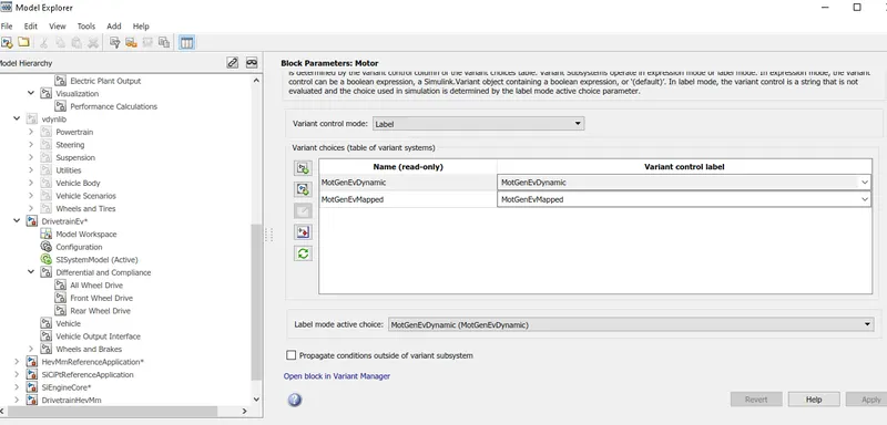
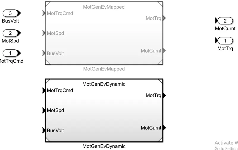
- The model type can be changed from initial mapped to dynamic by going to model explorer, selecting the motor and
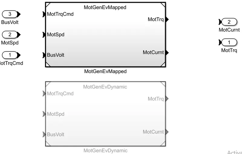
- selecting the MotGenEvDynamic and clicking on apply.
- The Wot drive cycle is selected in the drive cycle block and various parameters were set accordingly.
- With out change in grade and wind velocity in the environmental block the output plots can be seen as following:
- And the cursor symbol can be selected and in trace selection the signal values at that instantaneous point of time can be seen.
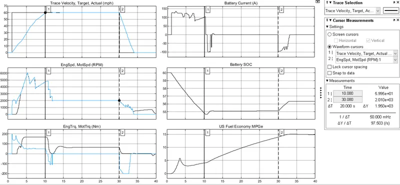
- Along with wind velocity(i.e 10 m/s) and grade(10) ,the simulation time was 40 seconds and time to start deceleration was at 30 seconds

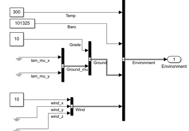
- The various environment parameters were modeled as shown in the figure given below.
- The plot was obtained after changes were made in grade and wind velocity.
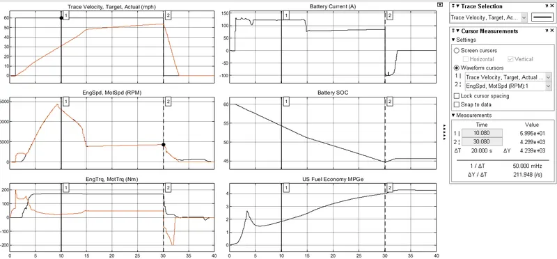
- From which we can infer that
- At 10 sec the actual velocity in the plot with out changes was 60 mph whereas the actual velocity in plot with changes is 29.9 mph this difference was very high (i.e the decrease in speed) because of the effect of added grade and wind velocity.
- Even this effect can be observed at 29.9 sec the actual velocity in the plot with out changes was 60 mph whereas the actual velocity in plot with changes is 55 mph.
- The battery soc has been gradually decreased and at 29.9 sec as observed in plot with out changes the battery soc was at 55% and in plot with changes the soc was 45%.The power consumed was high in plot with grade and wind velocity effects.
- At 29.9 sec,the engine and motor speed has been greatly increased in order for the vehicle to take grade(i.e from 2000 rpm to 4500 rpm) and
- At 29.9 sec the motor and engine torques have been increased very much than in plot with out changes ,engine torque (80 N-M),Motor torque (0 N-m and going negative) Whereas in plot with changes engine torque (168 N-M),Motor torque(49 N-M).
- And us fuel economy has reached 15 mpg in plot with out changes and 4.2 mpg in plot with changes which shows that the vehicle without changes has more economy(i.e saving)) and can go farther.
- At 10 sec the current consumed was about 150 amps in vehicle which took grade and 99 amps which did not take.
- The wot drive cycle has been taken for both HEV and EV models along with the effects of wind velocity and grade .
- The parameters varied in environment block were as shown below,the grade was taken as 10 and the wind velocity is taken as 10 m/s.
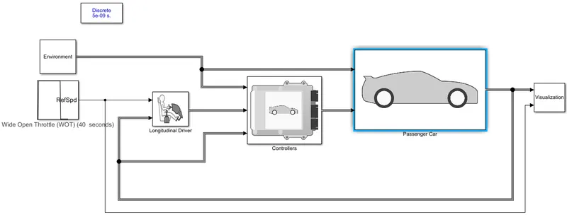
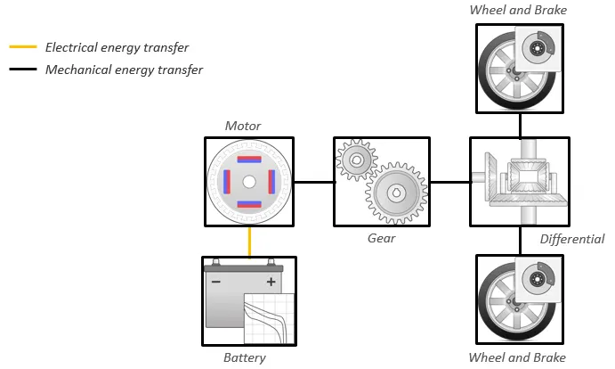
The electric vehicle reference application represents a full electric vehicle model with a motor generator,battery, direct-drive transmission, and associated powertrain control algorithms. Use the electric vehicle reference application for powertrain matching analysis and component selection, control and diagnostic algorithm design, and hardware-in-the-loop (HIL) testing.
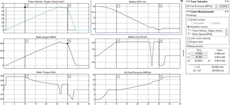
- The following was the plot obtained after simulation:
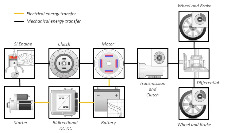
The hybrid electric vehicle (HEV) P2 reference application represents a full HEV model with an internal combustion engine, transmission, battery, motor, and associated powertrain control algorithms. Use the reference application for hardware-in-the-loop (HIL) testing, tradeoff analysis, and control parameter optimization of a HEV P2 hybrid.
-
Lithium-ion battery pack
-
Mapped electric motor
-
Mapped spark-ignition (SI) engine
This diagram shows the powertrain configuration.
- The following was the plot obtained after simulation:
By comparing both the model plots we can infer that
- At 10 sec the actual velocty of EV was 24 mph and in HEV it was 30 mph
- At 29.9 sec the actual velocity in EV was 58 mph where as the actual velocity in hev was 55 mph this was due to weight and power losses in hev..
- The battery soc has been gradually decreased in hev and at 29.9 sec as observed in ev the battery soc was at 78% and in HEV it was 45%.
- At 29.9 sec, in motor(110 N-M) and in HEV , engine torque (168 N-M),Motor torque(49 N-M).
- And us fuel economy has reached 23 mpg in EV and in HEV it was 4.2 mpg which shows ev has more economy and go farher.