Week 4 Challenge : CFD Meshing for BMW car
Objective
To clean the provided cad model of the BMW car, make surface meshing with the surface grouping and sizing per the challenge question. Additionaly, create wind tunnel, therefore volumetric mesh as well.
Geometry
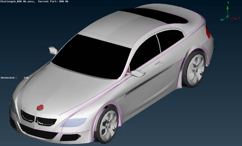
Figure 1
Singlecon detection
Firstly, we should resolve all errors within the geometry. Initially we look for so called "singlecons" which are opened surfaces. Singlecons are shown in red colour in the Figure below.
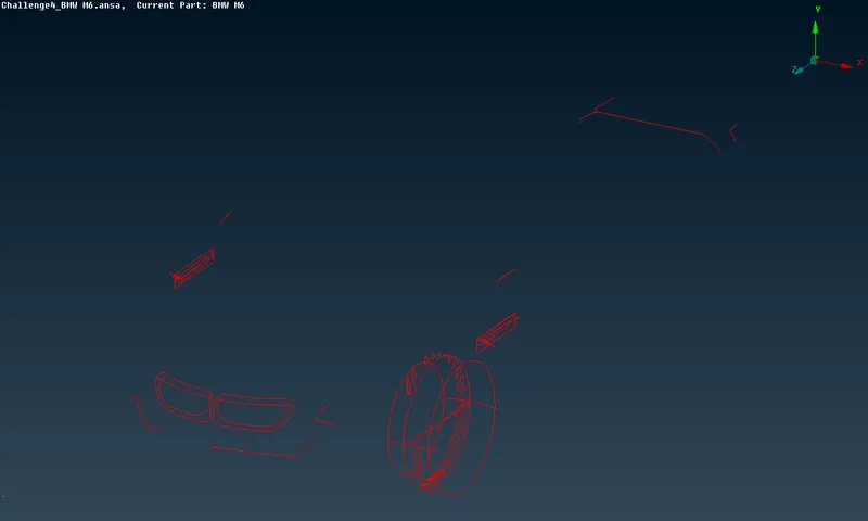
Figure 2
we try to resolve this problem using command "Topo", which tries to connect all those open surfaces.
Smoothing the surface of the car
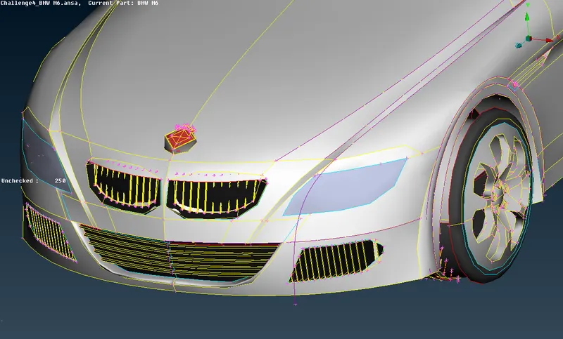
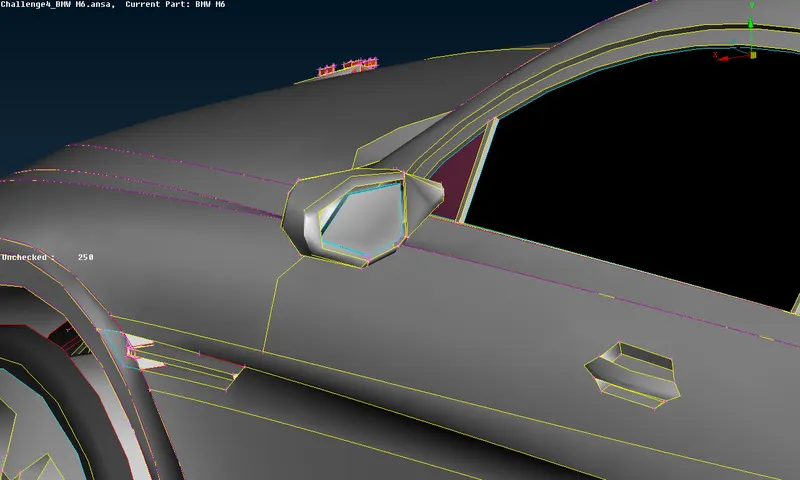
Figure 3
we can make surfaces smoother using the command "Length" in the mesh section
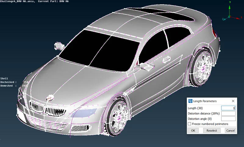
Figure 4
after setting Length as 1mm we get pretty smooth surfaces within the whole 3d model (Shown below).
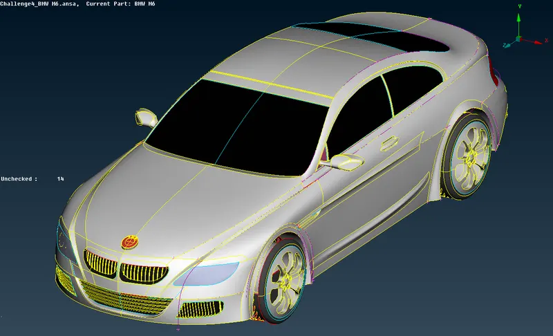
Figure 5
Half-cut
As the 3d model is symmetrical we can delete half of it (shown below) and then perform the topo cleaning procedure.
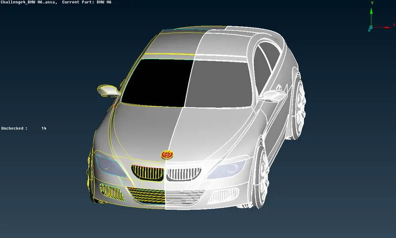
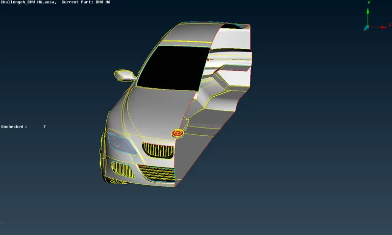
Figure 6
Resolving errors
Now, It's time to resolve all single and triple con errors within the half-cut model.
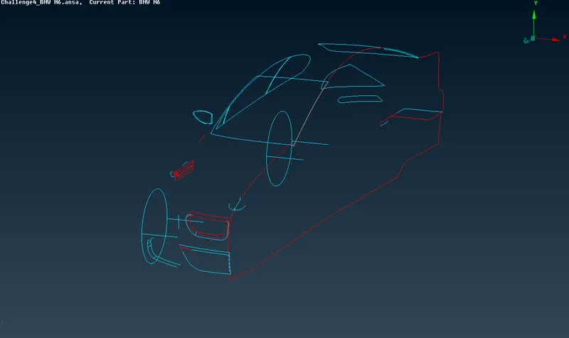
Figure 7
In the Figure 7 Singlecons are represented in red colour while triplecons are shown in blue colour (Figure above).
As there are a lot of single and triple con errors, I will not include all minor problem solutions, however some of the examples will be included.
While cleaning Geometry our goal is to maintain one volume throughout the complete 3d Model, therefore we only need doublecons, meaning during resolving errors we eliminate all single and triplecons within the whole Geometry.
Front Grill Geometry cleanup
- Before
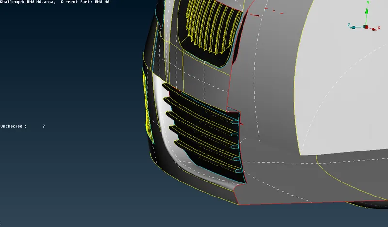
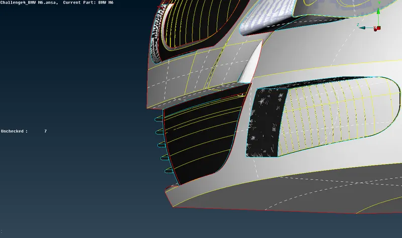
Figure 8
- After
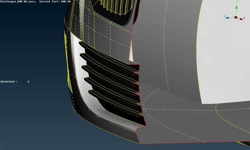
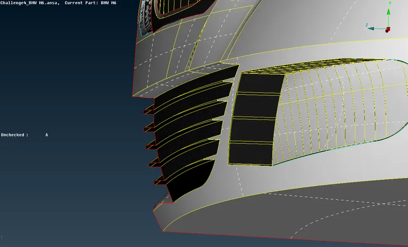
Figure 9
After cleaning the front grill, as you see in the Figure 9 within the grill area we have doublecons, however at the edges singlecons are remained which will be resolved after we finish cleanup and mirror the half-cut.
Side Grill Geometry cleanup
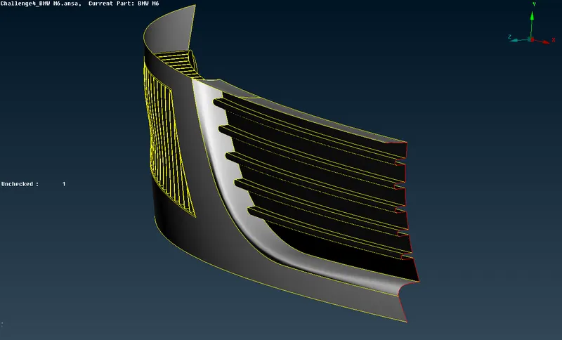
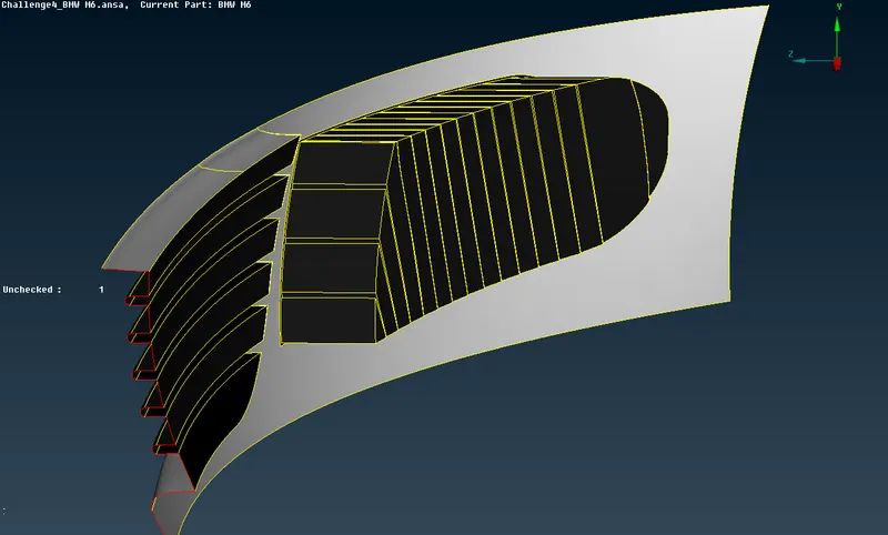
Figure 10
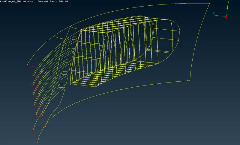
Figure 11
As you see in the Figure 11 we have only doublecons at the Front and Side Grills, therefore this areas are completely resolved.
Note: It's noticable that at the edge of the Front Grill we have singlecon which will be resolved after we bring back the second half of the 3d model.
Front upper Grill and the Logo cleanup
- Before
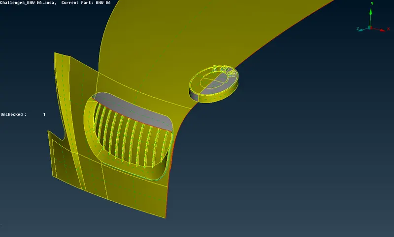
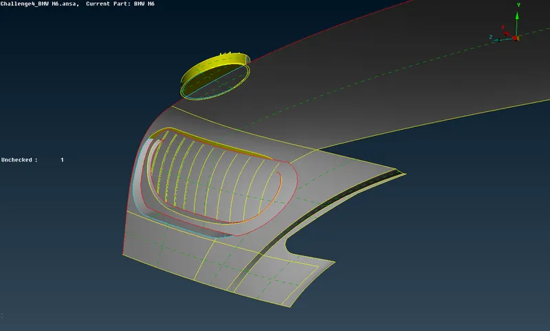
Figure 12
- After
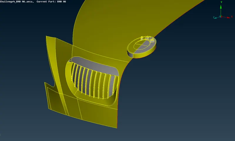
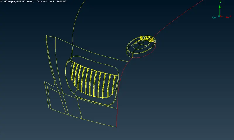
Figure 13
As shown in the Figure 13 all single and triple cons are resolved within the region.
Tyre cleanup
- Before
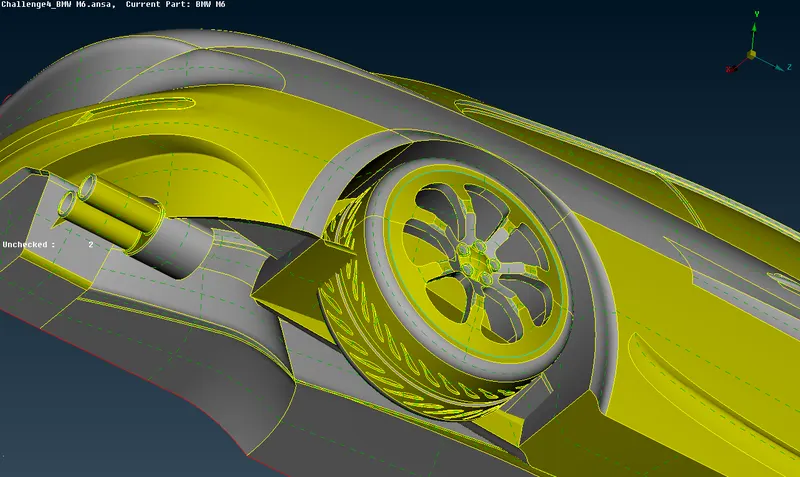

Figure 14
As shown in the Figure 14 tyre regions have triplecon and intersection issues. We should remove unnessessary surfaces to eliminate triplecons and intersections.
- After
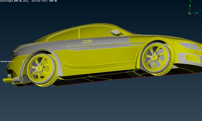
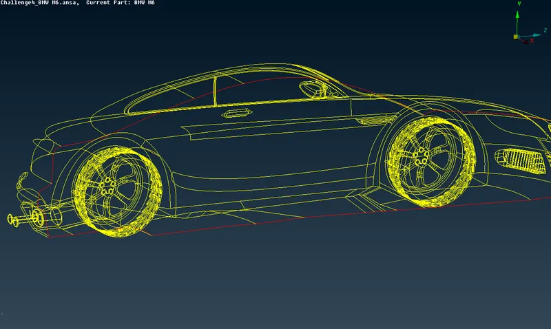
Figure 15
All Singlecons and Triplecons are resolved.
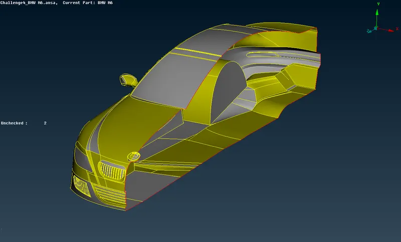
Figure 16
- Geometry check
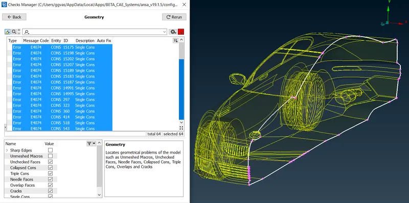
Figure 17
As shown in the figure 17 all the remaining error are within the half-cut edge, therefore those errors will be resolved while creating second half of the 3d model.
Property ID (PID)
Now it's time to apply property ID's for specific regions within the complete 3d Model.
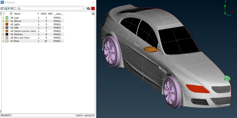
Figure 18
In the Figure 18 you see that the whole geometry has been divided into different regions, named accordingly and created Property IDs (PIDs).
Surface Meshing
Target lengths for the different parts of a model are as follows:
- Body - 3 mm
- Lights - 4 mm
- Grills - 1 mm
- Rims and Tyres - 2 mm
- Optical Rear view mirror - 2 mm
- Window - 2 mm
- Silencer - 3 mm
- Logo - 1 mm
Before starting surface meshing we set Quality criteria and Mesh Parameters
- PID "Body" ID 67.
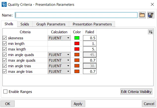
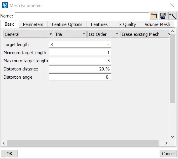
Figure 19
Note: Figure 19 shows Quality Criteria and Mesh Parameters for PID "Body" with the ID 67 per the Figure 18.
It's important to check if within the geometry there is any location where distance between doublecons is less than minimum target length value which in our case is 1mm.
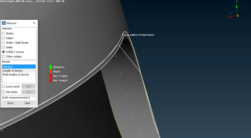
Figure 20
In the Figure 20 It's shown that at the rearside of the car at the rear light distance between two doublecons is approximately 0.3mm which means that if we try to generate surface mesh for this particular PID our "minimum target length" criteria will fail, therefore we should delete any doublecons if it's possible.
- Before
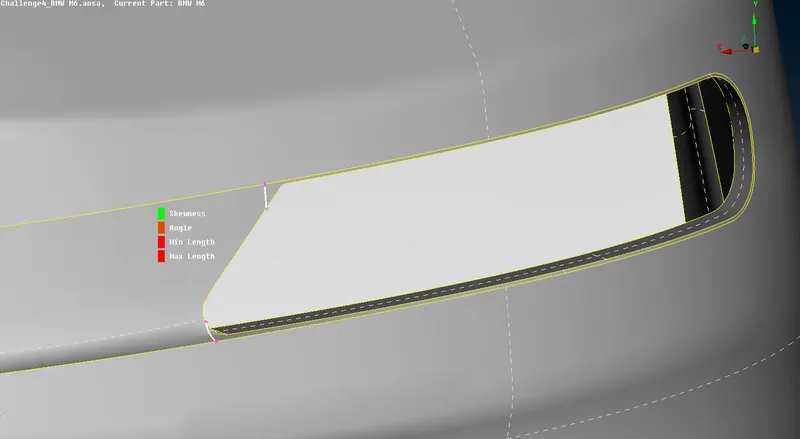
Figure 21
In the Figure 21 lines with the white mark is the cut lines used to cut one of the doublecons which we should delete to avoid mesh "minimum target length" criteria fail.
- After
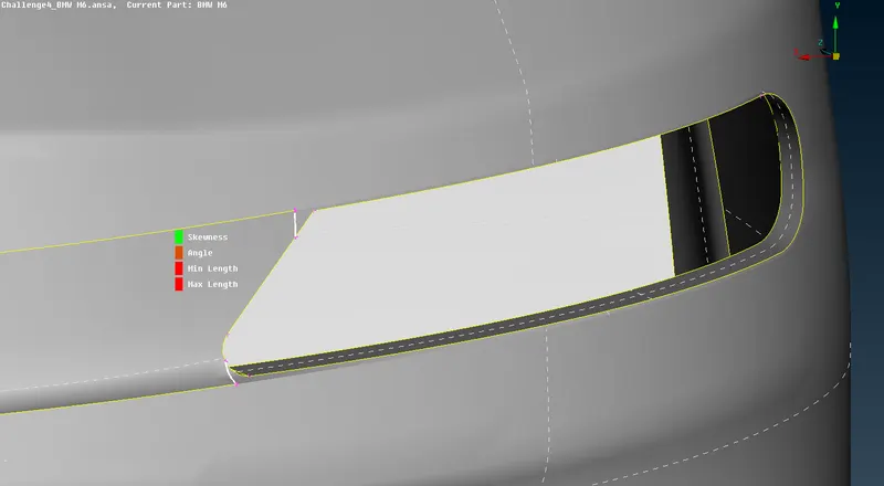
Figure 22
Unnecessary doublecon was deleted (Shown in the Figure 22).
- "Logo" Surface Mesh
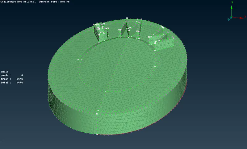
Figure 23
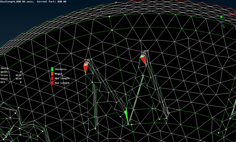
Figure 24
Unfortunately after generating mesh we have 8 elements off our quality criteria (Shown in the Figure 24), therefore we should resolve the issues.
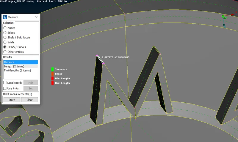
Figure 25
Per the Figure 25, we encounter surface where distance between two line sis 0.7mm, therefore we should delete those small surfaces to eliminate surface mesh issues.
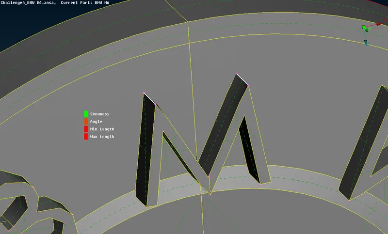
Figure 26
As shown in the Figure 26, we deleted small surfaces and now It's time to remesh the "Logo" to see if the issues were resolved.
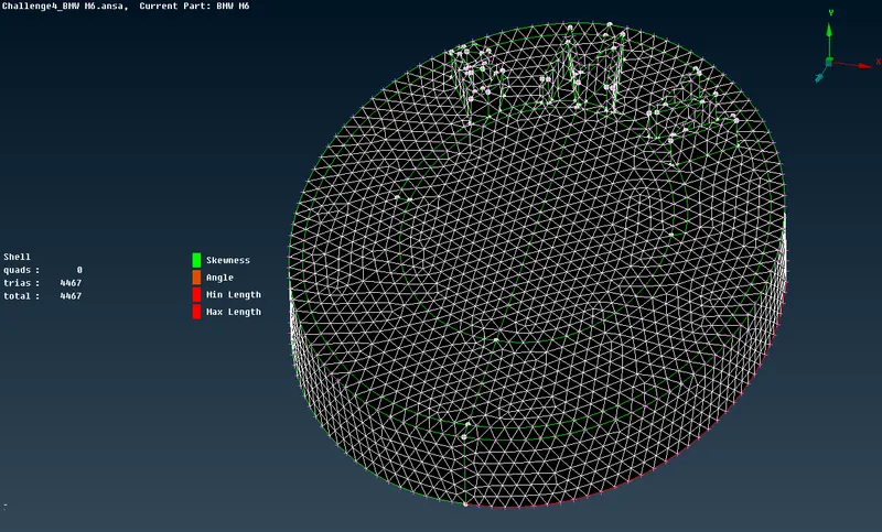
Figure 27
Fortunately all quality criteria off elements were resolved by deleting the small surfaces (Shown in the Figure 27).
- "Grills" Surface Mesh
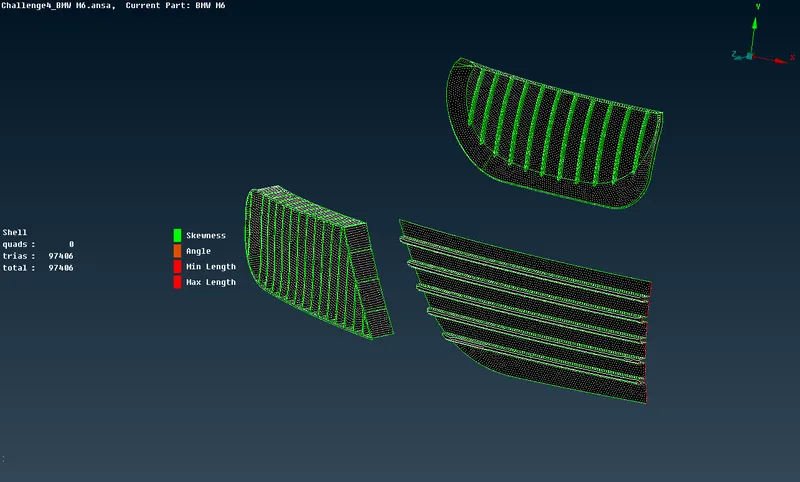
Figure 28
The same procedure of surface mesh generating goes with all the other regions. we applied required target lengths for the specific PIDs and completely meshed the surface of the BMW car.
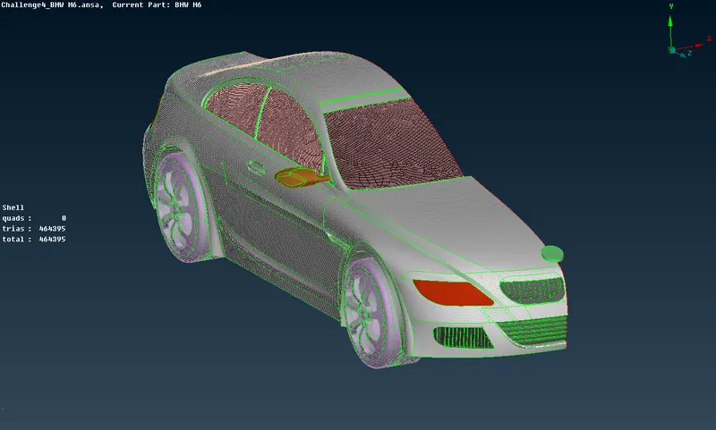
Figure 29
Creating the second half of the BMW car
In order to create the second half of the car we use command "copy"
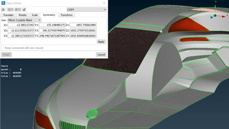
Figure 30
In the Figure 30 It's shown that to create the symmetry we should select 3 any points which are located on the edge of the symmetry plane. after selecting those points and executing the command we get the complete geometry (Shown in the Figure 31).
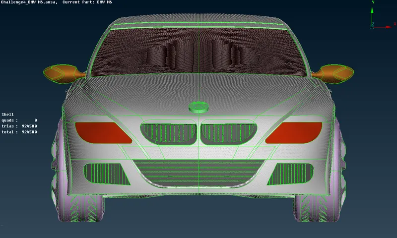
Figure 31
Creating wind tunnel
Before creating the wind tunnel surfaces we should know the distances at which the surfaces will be created. Firstly, we should find out the length of the car itself.
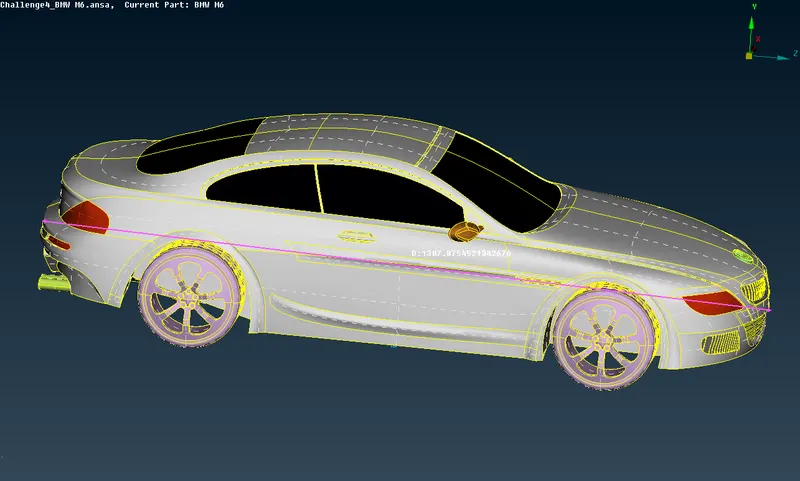
Figure 32
According to the Figure 32 the car length, in other words, aerodynamical characteristic length is approximately 1300mm. Now we create front surface nodes. wind tunnel front surface must be located at the distance of the 4 times the length of the car from the front edge of the car itself. therefore the distance should be approximately `4*x = 5200mm` (Shown in the Figure 33).
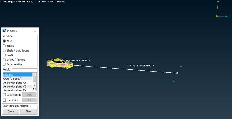
Figure 33
wind tunnel rear surface is located at the `6*x` distance which will be `6*1300 = 7800mm` (Shown in the Figure 34).
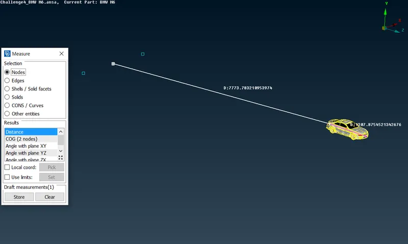
Figure 34
In order to determite the height of the wind tunnel we should locate the top surface at the `3*x` distance from the top surface (roof) of the car, which is `3*1300 = 3900mm.` (Shown in the Figure 35)
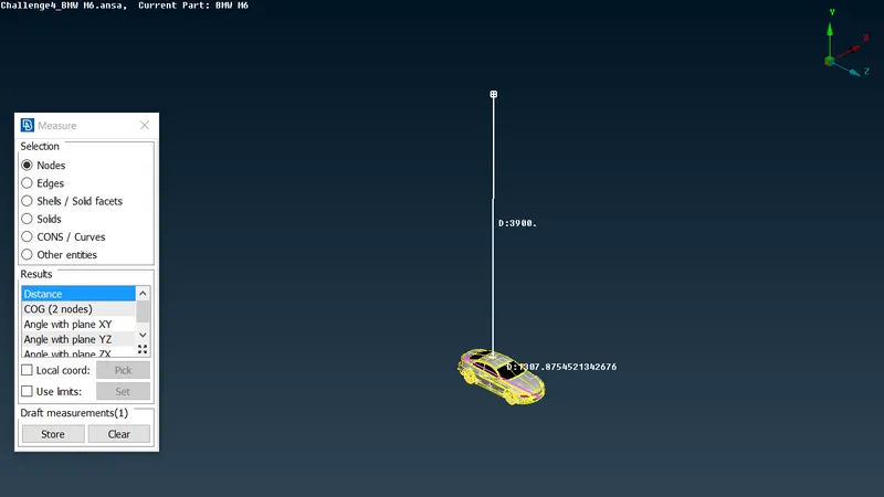
Figure 35
Wind tunnel width should be `2*x`, therefore `2*1300 = 2600mm` (Shown in the Figure 36)
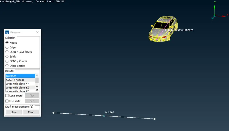
Figure 36
In the Figure 37 base surface of the wind tunnel is shown.
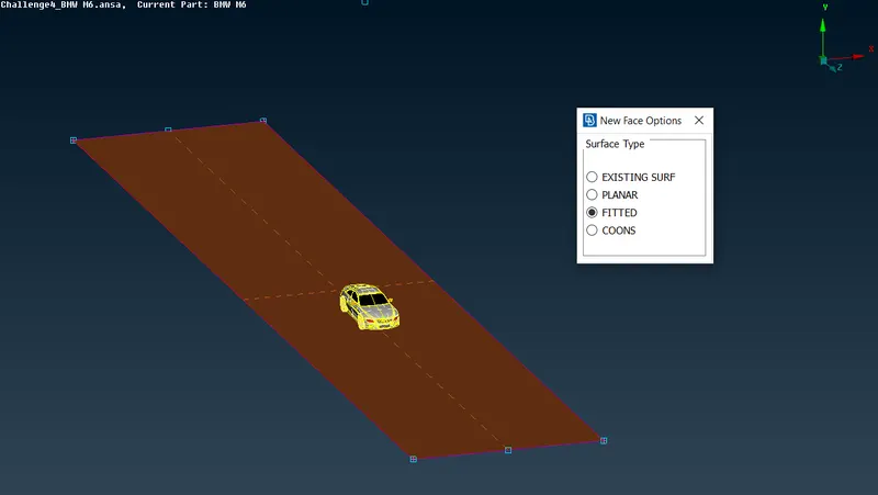
Figure 37
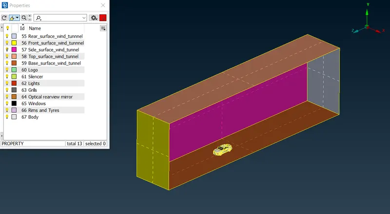
Figure 38
- Surface Mesh of the Wind Tunnel.
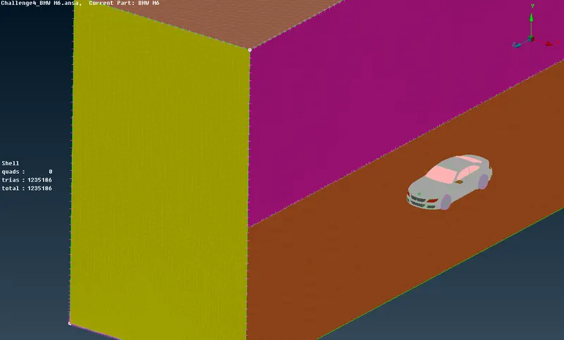
Figure 39
Volumetric Meshing
In order to identify Volumes we sue command "define - Autodetect" which detected 8 volumes.
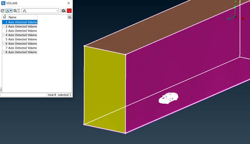
Figure 40
In the Figure 40 the first detected volume is the volume we need for the CFD simulation, This is the volume between the car and the wind tunnel surface, all other seven volume are solid volums (car volumes) which should be deleted.
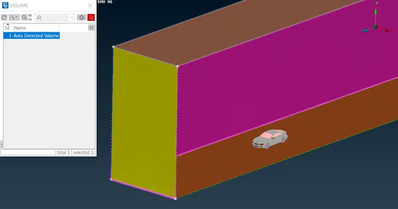
Figure 41
In the Figure 41 the volume between the car and the wind tunnel surface is shown. Now we can perform Volumetric meshing using the command "Remeshing", however the number of surface mesh elements is too high and as we know the size of the tunnel is pretty close to the real one, therefore meshing would take a lot of time. Unfortunately we will not make volumetric mesh, but will provide the ANSA file.
Conclusion
We successfully performed topology cleanup of the entire model, created suraface mesh per the given required mesh element sizes for specific surface regions, Furthermore created Wind tunnel around the car and advanced the geometry to the one volume model which could be used for further reaserch (CFD).