Week 4 Challenge : CFD Meshing for BMW car
Aim:
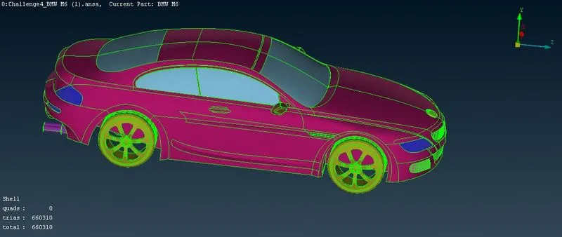
For the given model, check and solve all geometrical errors on half portion and Assign appropriate PIDs. Perform meshing with the given Target length and element Quality criteria. After meshing the half model, Do symmetry to the other side.
OBJECTIVE -
- To create half model of the given geometry and solve all geometrical errors.
- To perform topology cleanup,generate PID's and generate surface mesh.
- To create wind tunnel.
- To generate volumetric mesh from the surface mesh and do symmetry.
Steps involved in complete process:
- Topo cleanup - topo cleanup is basically cleaning geometry by removing unwanted surfaces and solving triple and double cons
- Geometry is irregular in shape after we exported file to ansa. Irregular means surface irregularities , removing these is our first step
- Start with topo cleanup for eachh parts eg: tyres, grills, logos, windows, lights and batteries
- Use entity mode while working.
- Divide geometry into half as geometry is symmetric.
- Start with 2D meshing after topo cleanup
- Start with 3D meshing after 2D meshing.
Original Geometry-
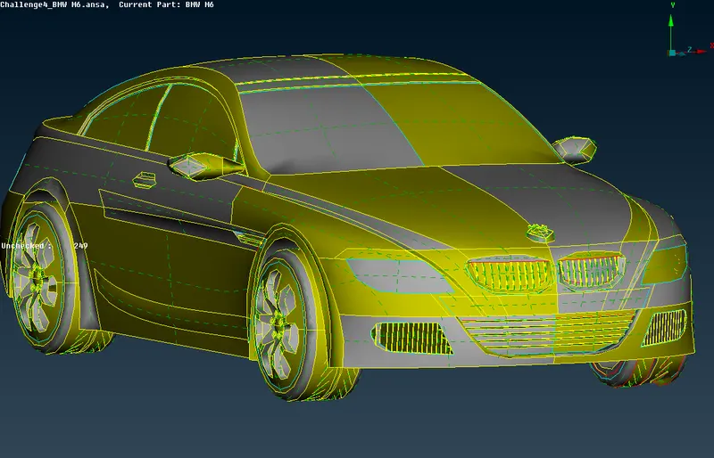
Single and Double cons-
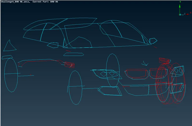
Cons which we see above picture needs to be solved in order to complete topo cleanup.
TOPO CLEAN-UP:
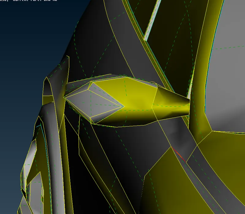
- Original geometry first error is that cons are irregular, this is overcome by going into mesh tool
- Go to mesh tool and select length perimeter of 1mm for complete body, this will resolve all irregularities in cons alignment and body will appear in proper shape.
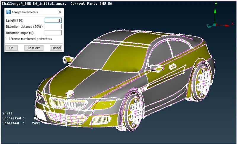
fig 2: meshing for smooth edges
- Since the car is symmetric from the middle to any end, we can delete one-side of the car and perform the necessary operations on the car and use symmetry option to produce the complete car.
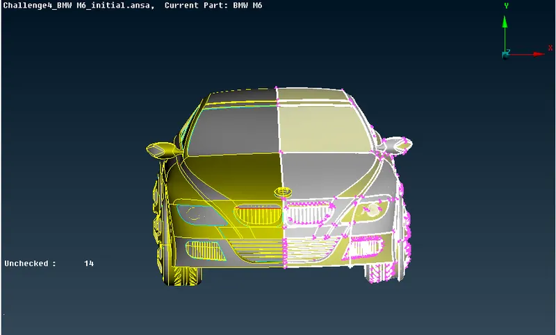
fig 3: deleting half car body
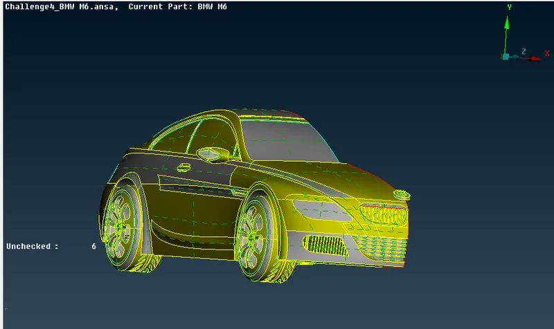
fig 4: performing topo clean up
Now will delete all unnecessary surfaces from inside the car model,as we are concerned about outside of the car and area between car outer surface and wind tunnel.Any extra surfaces will create unnecessary volumes utilising memory and time.As shown in the below pictures will perform topology cleanup on our model and will try not to have any single or triple cons except,at locations around which symmetry will be performed.Will remove any extra hot points.Also will use CUT tool to create cons whereever necessary.Also delete any overlapped surfaces.Overlapped surfaces may cause an error while going in the volumetric mesh.Once we go in the volumetric mesh ,we may get generation error,that error is basically showing us overlapped surfaces.
Front Grill Area:
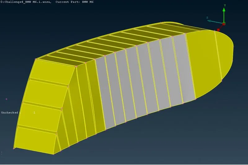
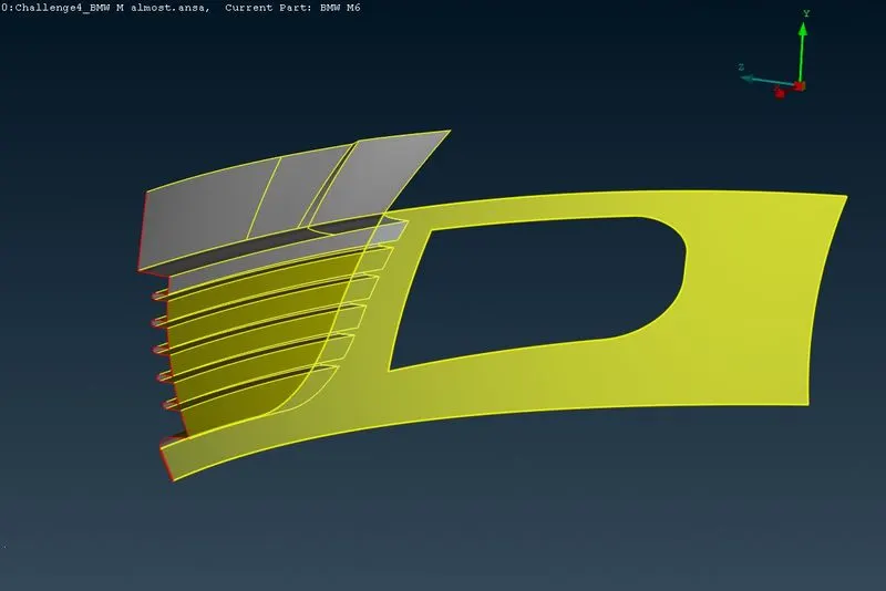
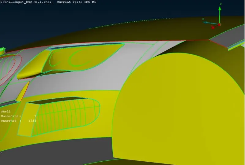
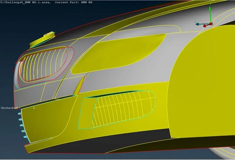
- Begin with the front grill area and the headlights, delete all the extra parts to have a single volume throughout the car.
- Now to remove the single and triple cons and to maintain single volume, to create a single volume we need to have double cons everywhere, to do this we need to performs few cuts and re-surfacing of parts to maintain a single volume.
- After performing the cuts and removing the extra triple cons surfaces by using delete option and other tools, we can now remeshing create surfaces and maintain a single volume.
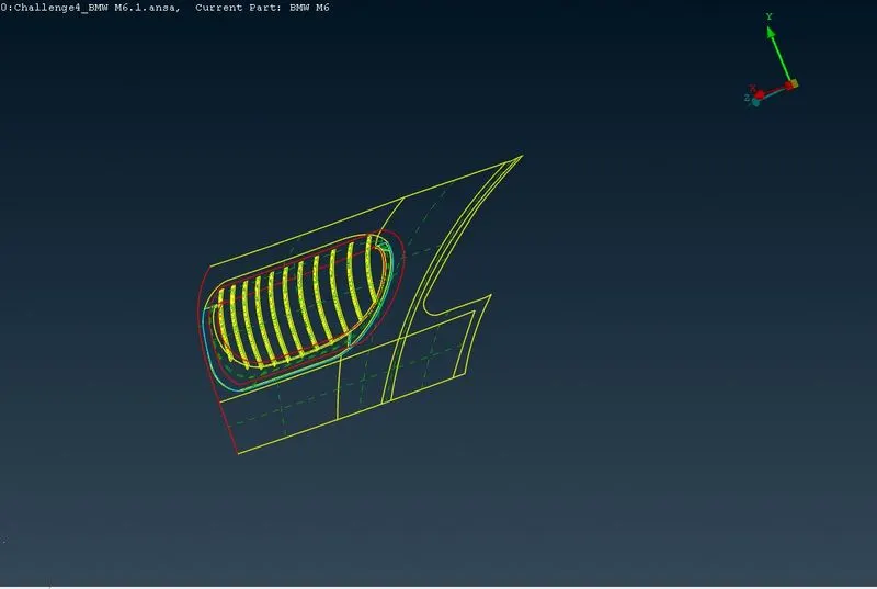
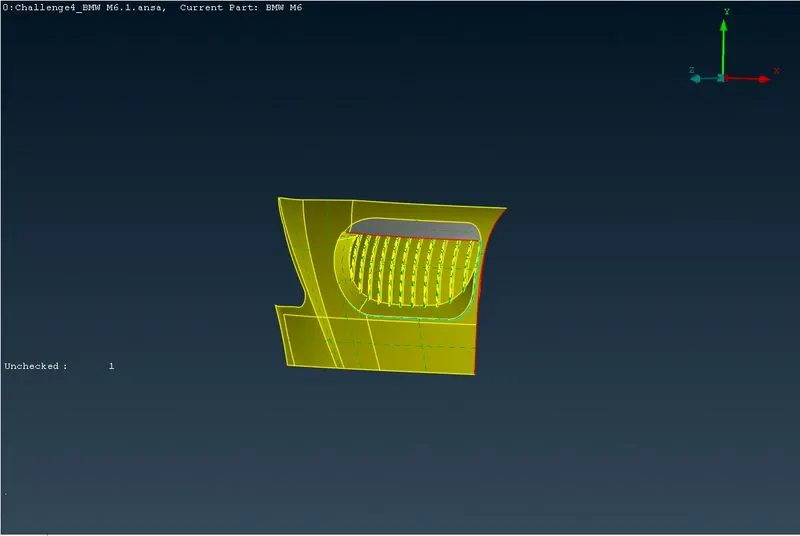
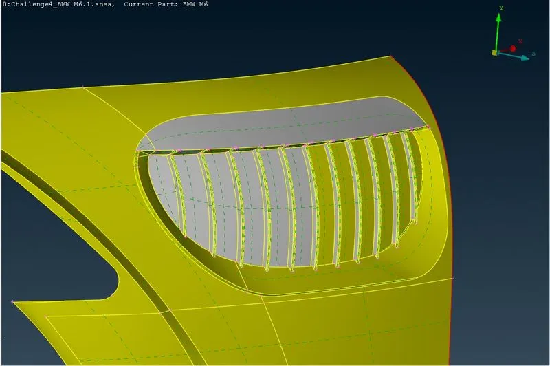
Fig:Geometry Cleaned Grill
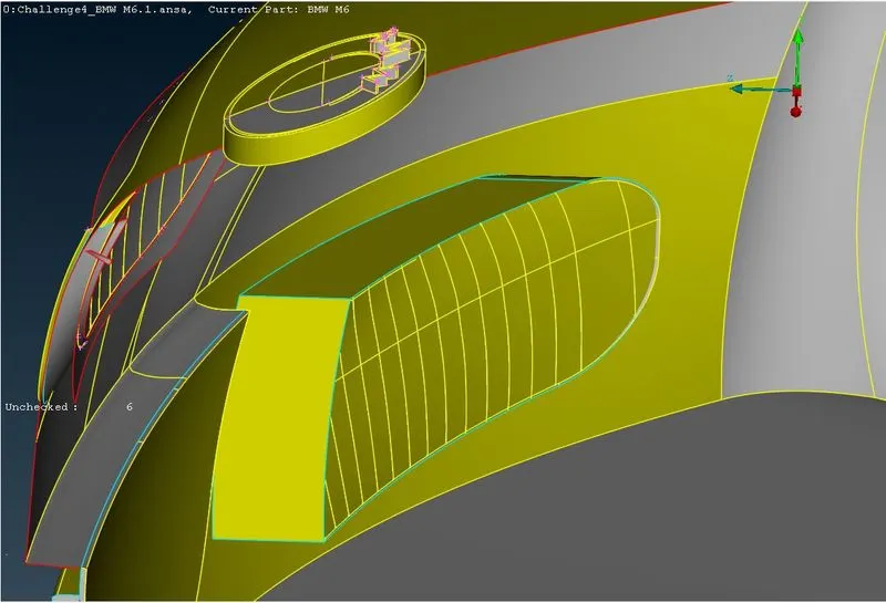
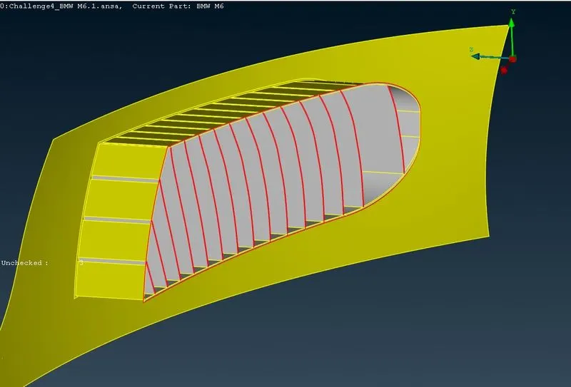
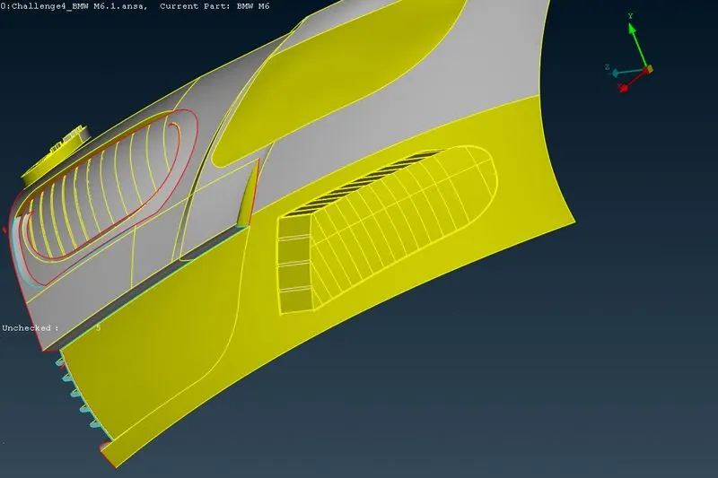
Middle Grill -
Windows, rear lights, roof region ,mirror and logo:
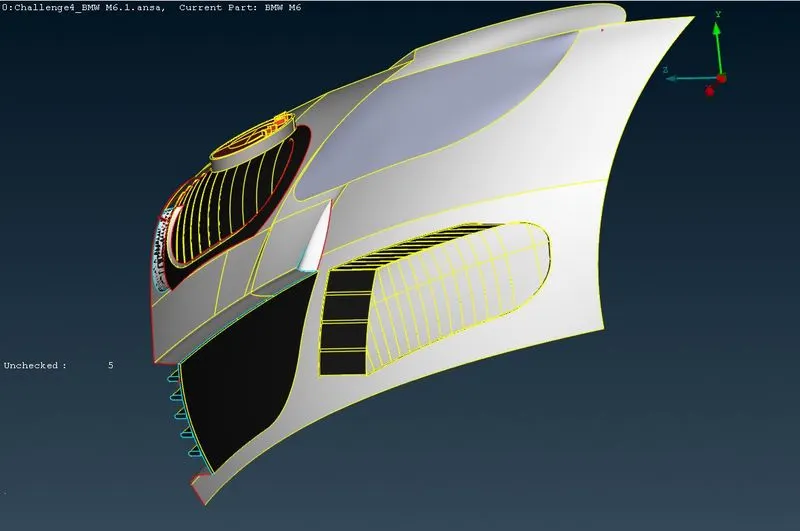
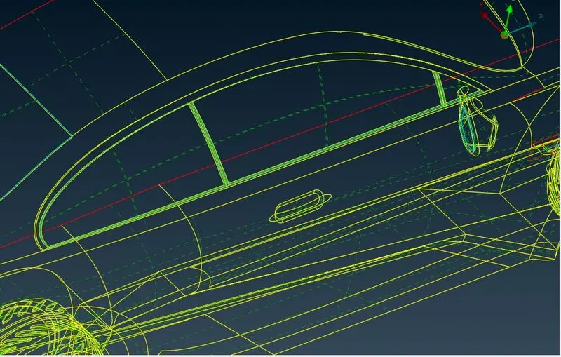
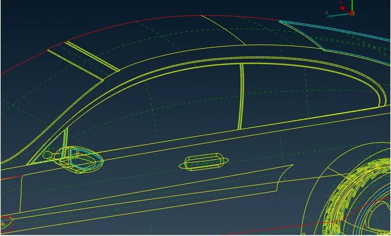
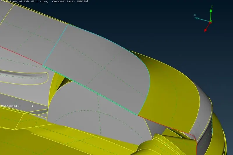
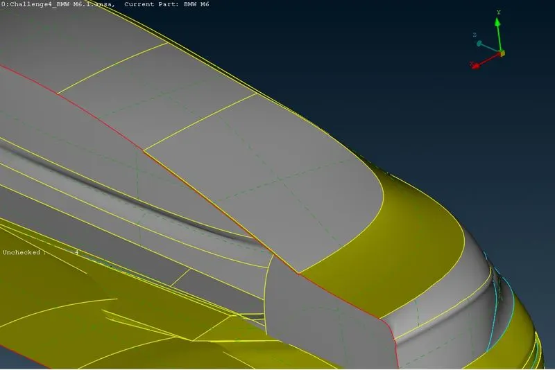
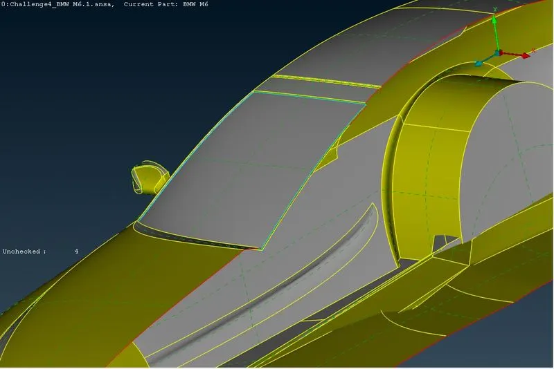
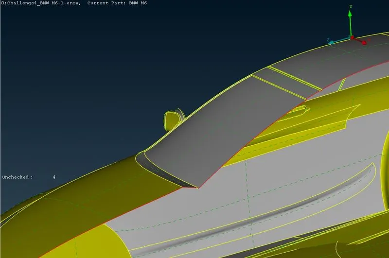
- Delete the triple cons or extra surfaces to remove the triple cons, these double surfaces are not necessary since we need to have a single volume.
- Do the same for windows, rear lights and roof area where extra internal parts are present which is of no use to create surface or volumetric mesh.
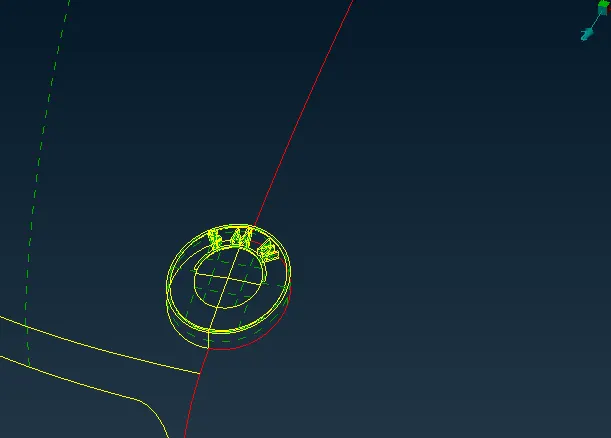
- The logo of the car is under a sinlge surface, therefore using project cons, create a separate surface and delete the extra surfaces to maintain a single volume.
LOGO:
- Focus on two faces of logo, top & bottom.
- Start with bootom surface , delete overlapped surfaces. You will see logo hollow from bottom after deleting bottom surface
- Then go to top surface there you will another overlapped surface and delete it.
- Use not tool and hide top surface inside you will and extended surface attached with top surface inside logo, delete it.
- There is circular strip surface on top logo along boundary, delete that surface and use coons option to create a new surface at the gap created between boundary and middle part of logo.
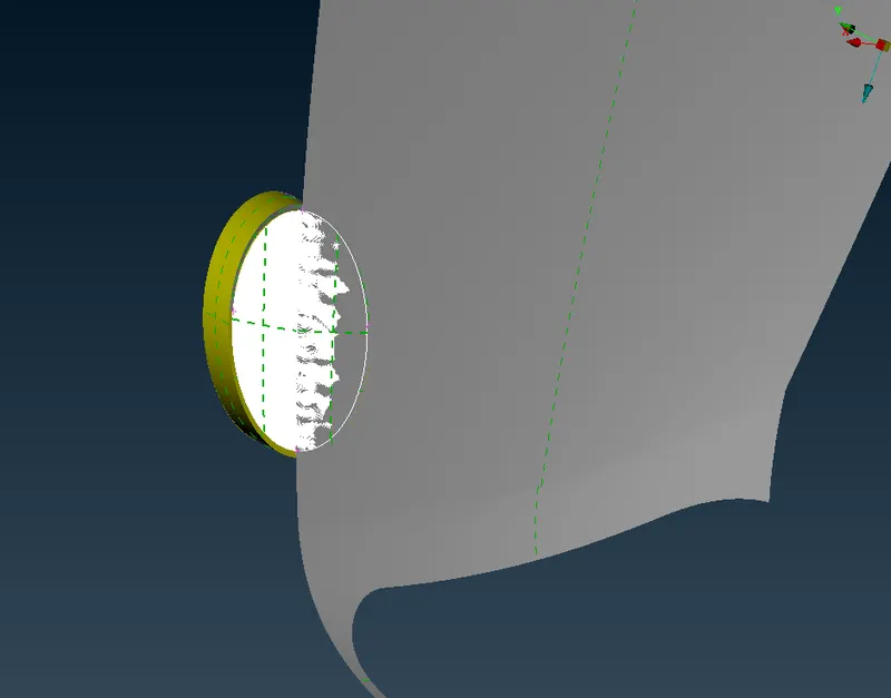
- Geometry cleanup for logo is done
Windows:
Mirror:
- Isolate the mirror and perform topo clean-up, hide the surfaces blocking the the triple cons view.
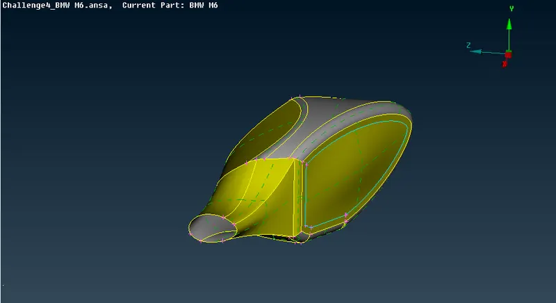
fig:Optical rear view mirror
- Delete the extra surfaces and create a single volume, also at the car and mirror connection region perform extend on the car surface and create a single volume by deleting the extra surfaces.
Front Lights:
Rear Lights:
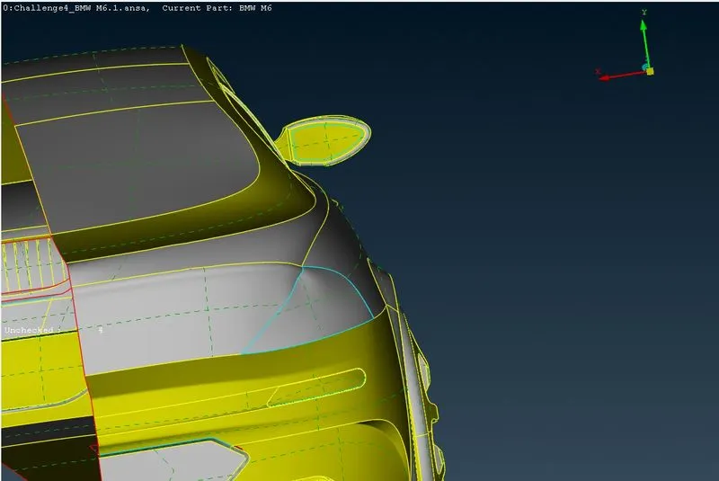
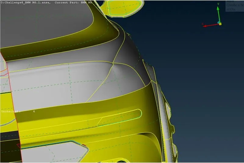
Design Feature:
- Perform topo and identify the triple and single cons, and delete the extra unwanted surface to maintain a common volume.
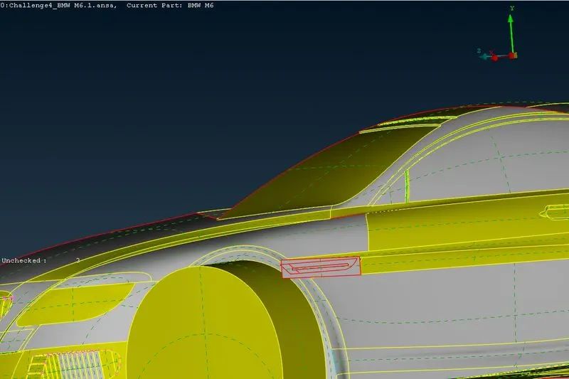
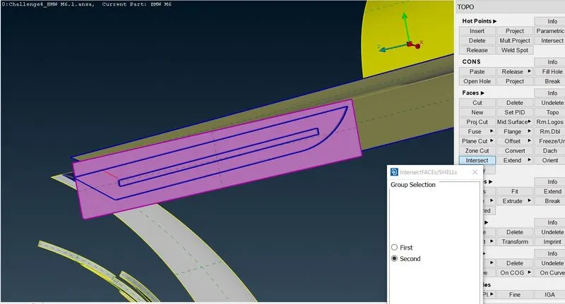
fig:Design feature of car
- Use the intersect option to identify the triple cons at the intersection area and can delete the smaller surfaces individually.
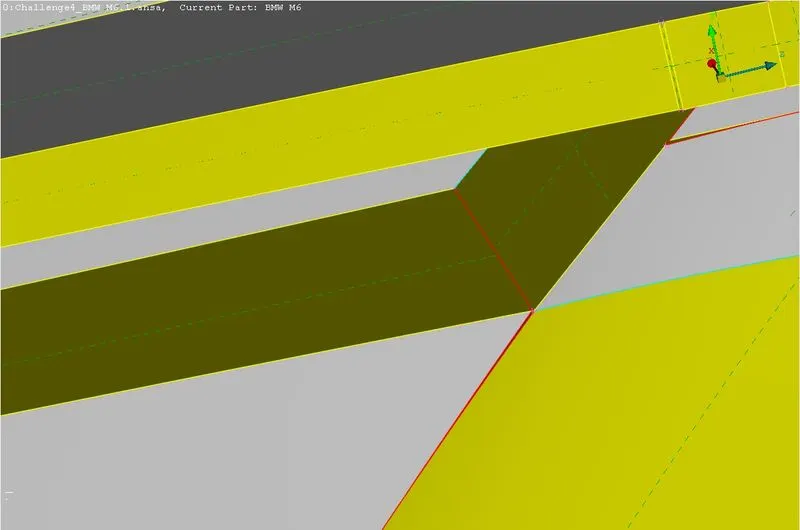
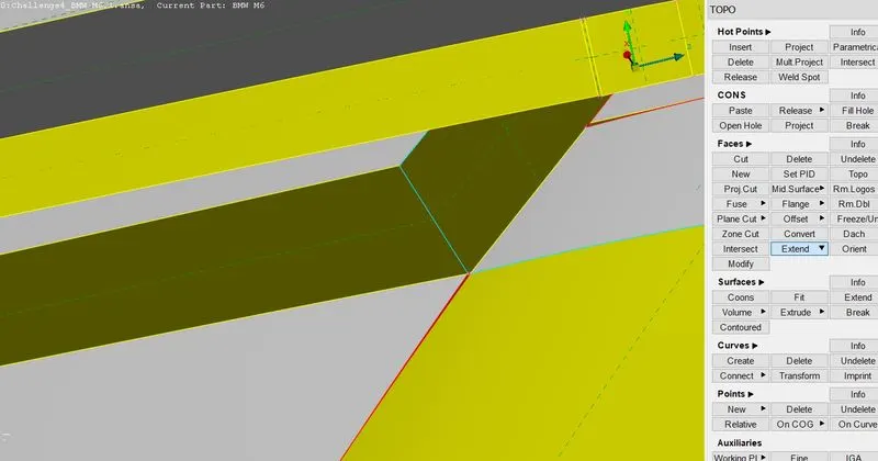
- Extended the single cons on the adjacent surface to create triple cons and delete the unwanted surfaces by doing that.
- Delete and re-create surfaces accordingly to have a smooth and perfect shape at tight corners. Also uncut the lines which are necessary which might cause trouble during meshing.
Tyres:
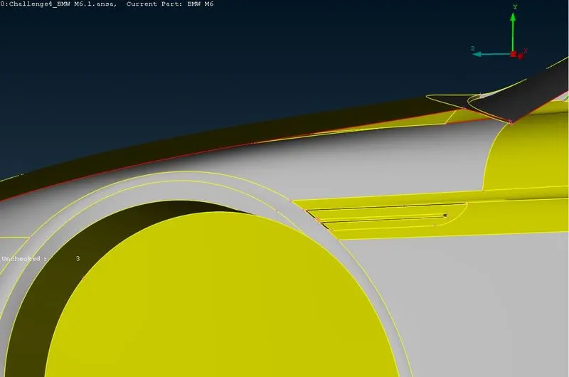
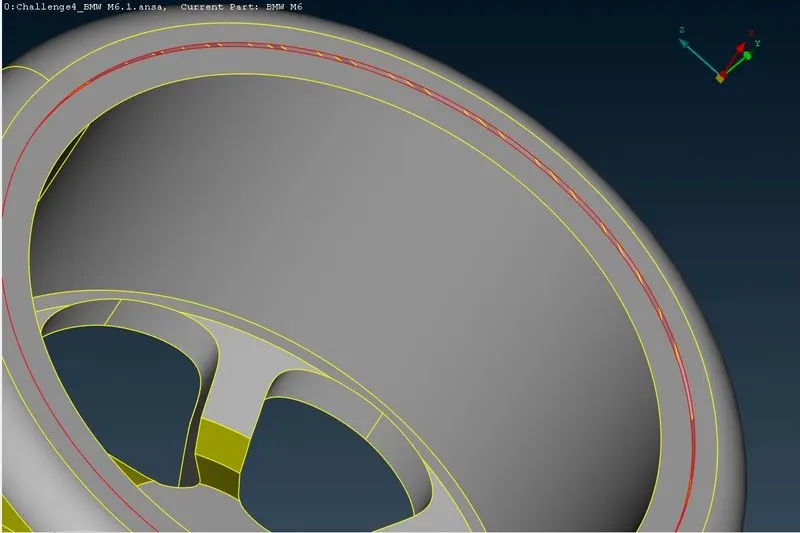
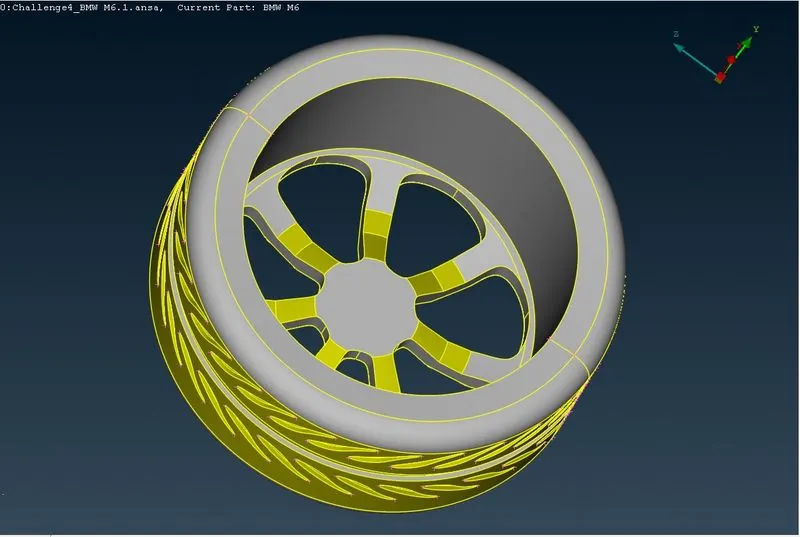
- Isolate the wheels to perform geometry clean-up, to rectify the triple cons, hide the surface blocking the view and delete the overlappng surfaces causing triple cons.
- Create larger surfaces after deleting smaller surfaces which are parallel to eachother.
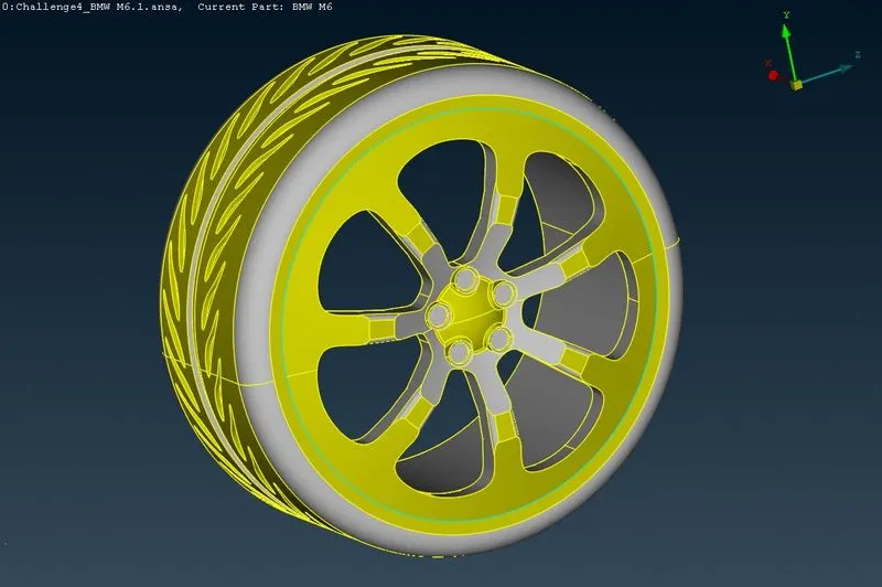
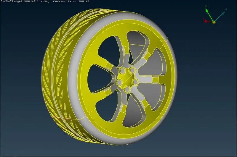
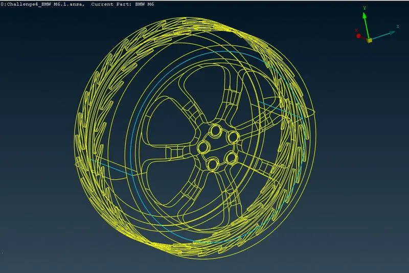
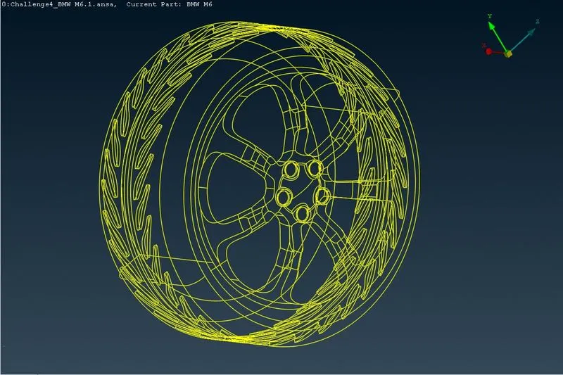
Fig:Tyre PID and wire frame model
Base Region:
- The base of the car is intersecting with the tyre, therefore we need to delete the excess surface and also delete the extra design surfaces which cause smaller edges, this causes problems while creating mesh.
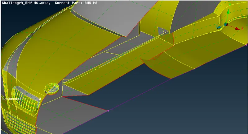
fig:Using curve feature while topo clean-up
- Therefore we need to clean the entire base and create new surfaces accordingly having smooth edges.
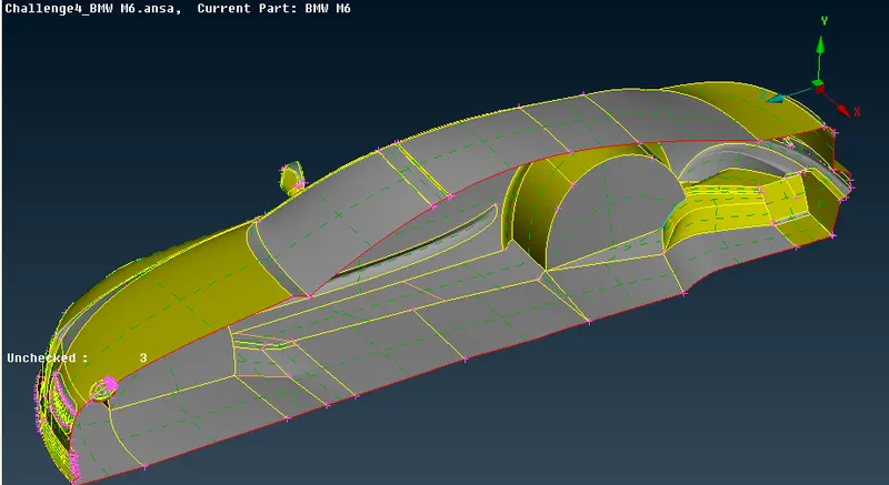
fig:Base geometry clean-up
- After making the surface changes, we need to check if the base surfaces has no intersection with the tyre region.
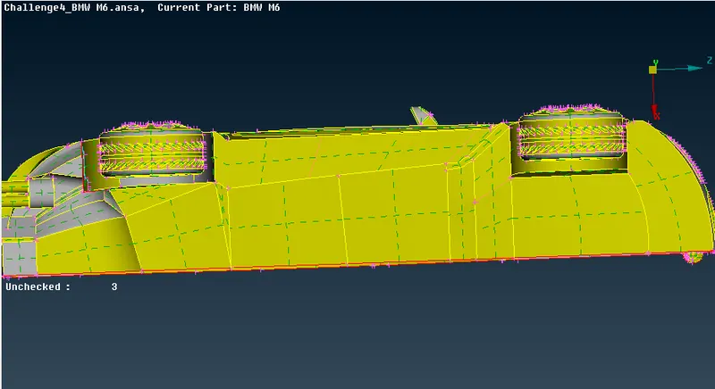
fig:checking interference between tyre and body
- After checking and performing topo-clean up for the entire half car model. We need to perform geometry checks to find small cracks are unchecked faces extra which is not good for the geometry, therefore we need to perform checks and clean the geometry accordingly.
Final Geometry After Topo Cleanup -

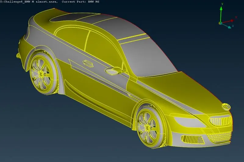
Final Checks After Topo Cleanup:
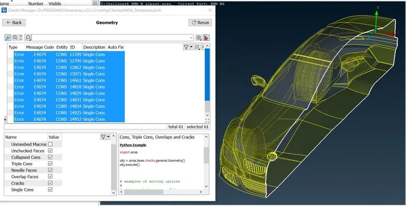
- From the above image we can see that, only single cons are left which will be use in creating symmetric other side.
- Once the geometry is checked and has no errors, we can now assign names to different components using PID.
PID Creation:
- Now lets create PID's which will come handy during meshing.To do that follow below procedure.
- Click Properties => right click and select New => select PSHELL => again select PSHELL => Give name as Silencer => ok.
- Simillarly create body,lights,window,grills,rims and tyres,optical rear view mirror and logo PID's.
- Now ,to assign each PID to it's respective part follow below steps.
- Right click on PID name => Apply => select the respective part => click middle mouse button to confirm.
- Simillarly assign all the PIDs.
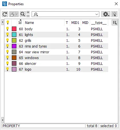
Fig:PID Table
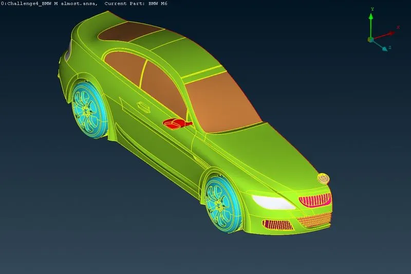
- We are making sure that at the end we only have larger body PID,thus we have assigned all the small PIDs.Now all remaining components will be in Body PID.
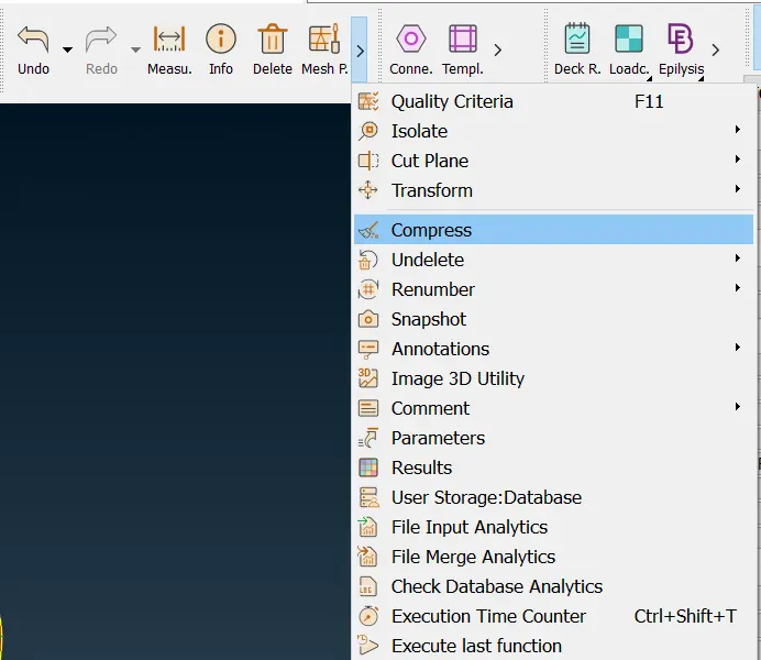
- Now if we try to delete the shell properties we got an error as "Selected ID is used by adeleted face and can not be deleted".But there aren't any surfaces showing after selecting show only for Shell_Property PID.Thus we will delete it using brute force.Thus select arrow symbol beside the measure tool and select compress then press ok.This will
delete the unnessary PIDs. - The empty PIDs with the default names were removed forcefully by going to: Compress -> Ok
Surface Meshing:
The preproccesing to the actual meshing process is complete. The surface mesh will be generated first under Classic Mesh Model. The PIDs were grouped by mesh size for convenience. For each size: perimeters, macros, mesh parameters and quality criterion were defined as follows,
Target Lengths:
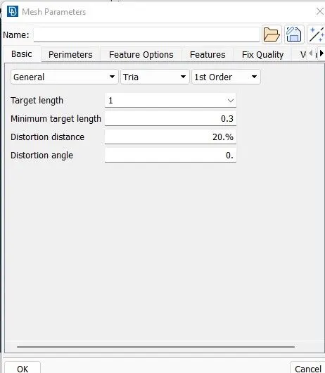
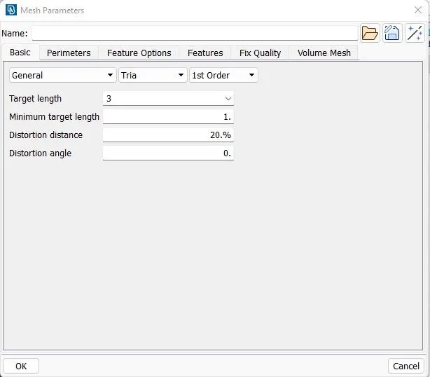
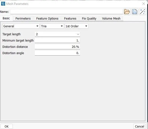
Target lengths for the different parts of a model are as follow:
Body - 3 mm
Lights - 4 mm
Grills - 1 mm
Rims and Tyres - 2 mm
Optical Rear View Mirror - 2 mm
Window - 2 mm
Silencer - 3 mm
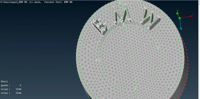
Logo - 1 mm
Surface meshing:
Due to different target lengths given for meshing, that's why we have to mesh all the components individually.In the body, the PID region is in contact with other PIDs so that the mesh length variation at the boundary region of 2 different pids causes the mesh to erase or cause mesh failure in that particular region. Therefore, while entering the perimeter under a length in the mesh. select the region which is not in contact with other PID regions. This helps in avoiding the mesh being erased and can later be edited to erased and can later be edited to erase the off elements.
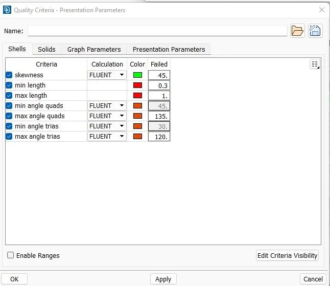
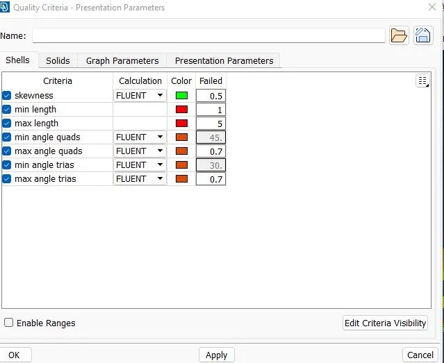
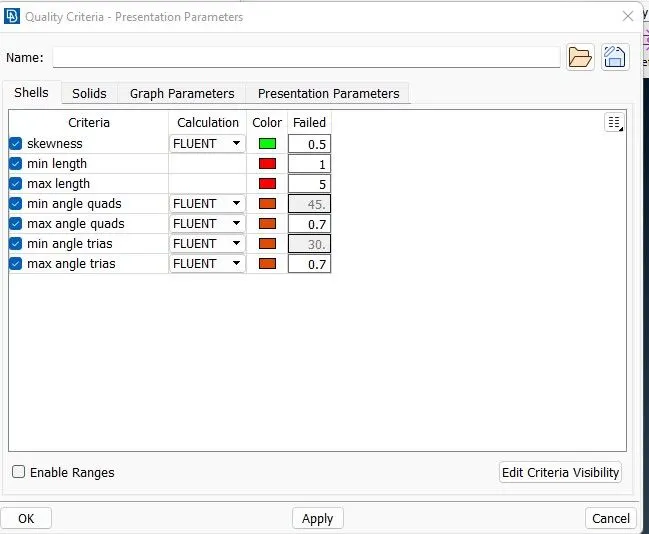
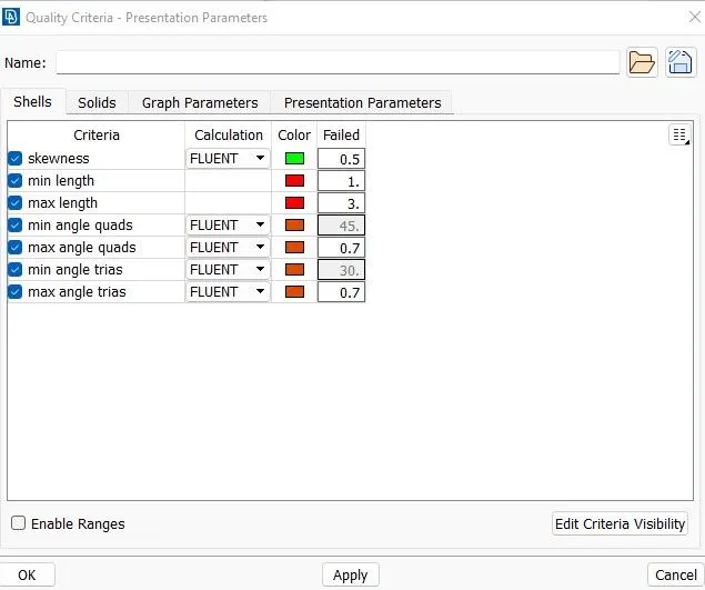
First of all wisely choose the Quality criteria parameters which are only required : -
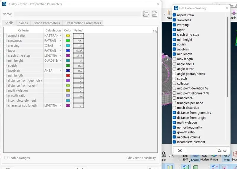
- Individual elements are meshed with respective mesh length with minimum and maximum length.
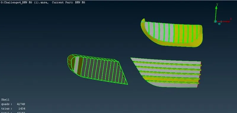
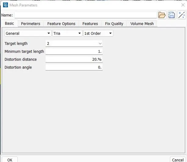
- Grills are isolated and give a mesh length of 1mm with minimum and maximum length of 0.5mm and 2mm with triangular elements and for Quality criteria provide appropriate mesh length. Here are quality criteria's and mesh element size for all the components.
BMW LOGO:
BMW logo:
GRILLS:
Meshing of Grill:
BODY:
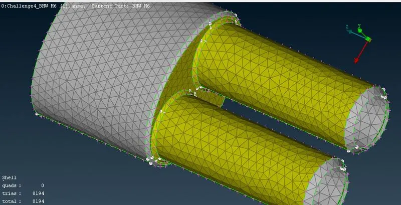
SILENCER:
Meshing of Silencer:
WINDOWS:
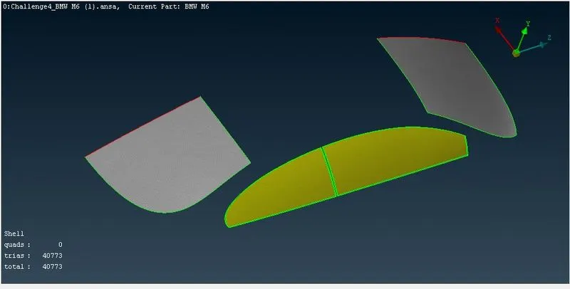
Meshing of windows:
Meshing of tyres:
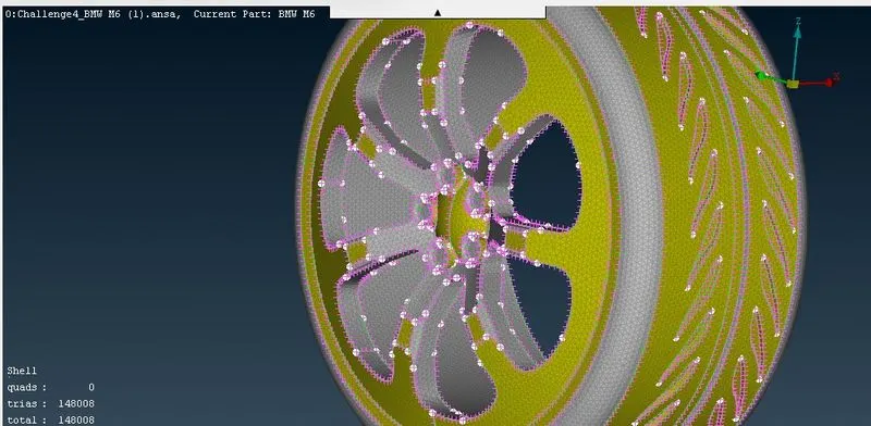
Meshing Of Lights:
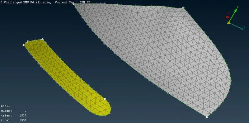
Meshing of Rear reflected mirror:
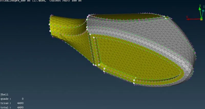
- The mesh is seen in Hidden Mode and ENT wise, which will show off elements which are violating the criteria. So we need to remove off elements by using options such as MOVE, SPLIT, RECONSTRUCT,SMOOTH the grid respectively ,from this we can improve our meshing.
-
Once the off elements's number reduced to 0 then meshing is done successfully, and Similar method is used for other PID's.
-
Symmetry need to be performed on the other half of car in which the all the components with mesh are copied directly to the other side using Transform option from the top side option list.
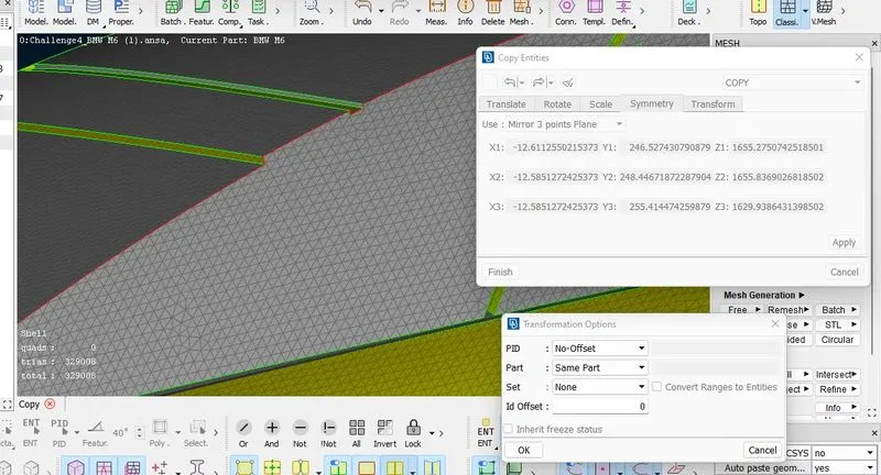
WIND TUNNEL :
Data for wind tunnel are as follow:
The wind tunnel dimensions are, if x is the lengths of car then
Front of wind tunnel is 4X from the car.
Rear of wind tunnel is 6X from the car.
Top of wind tunnel is 3X from the car.
Side walls of wind tunnel are at X from the side portion of the car
Bottom of wind tunnel is in close proximity of wheels
Points are created by using 'Reative option' in points of Topo Deck.
Total length of the Car:
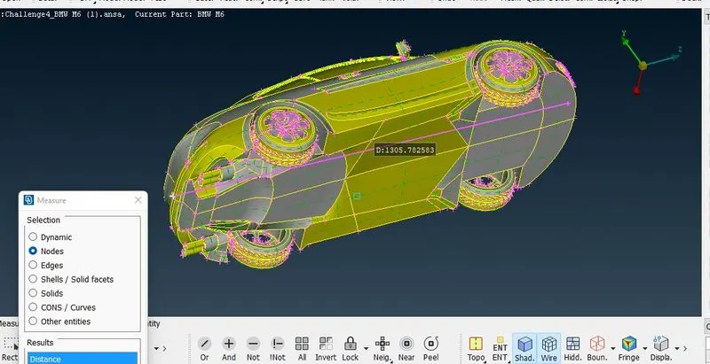
Create point at front:
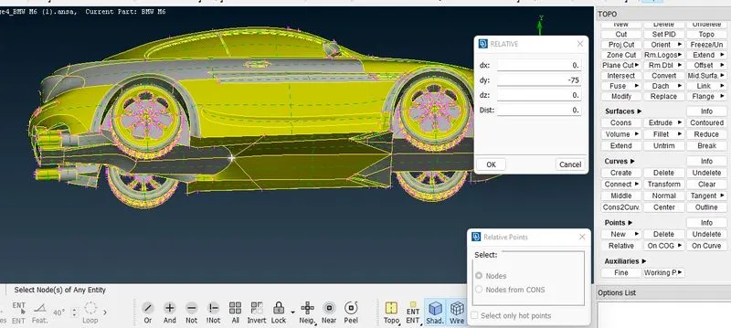
Create point at bottom:
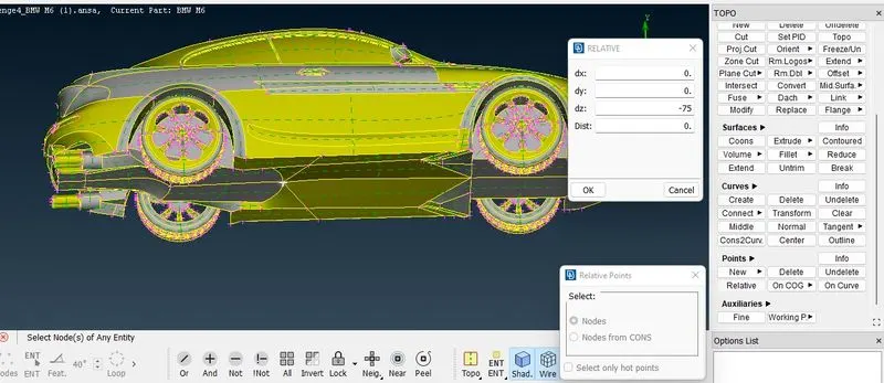
Move point at -75 of the dx:
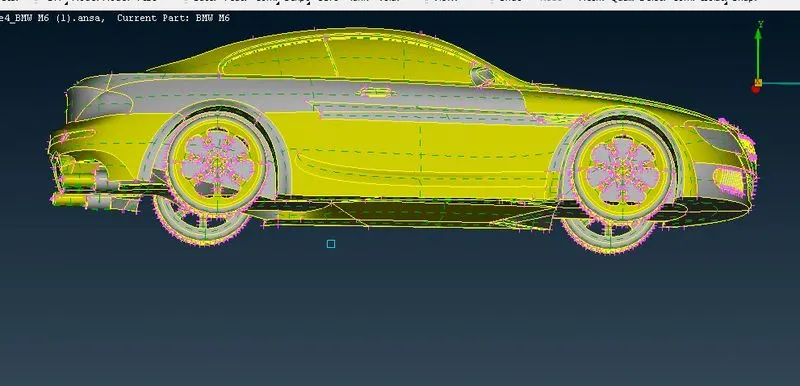
Create point at Rear:
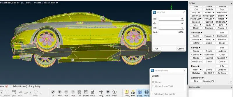
Create point at Top:
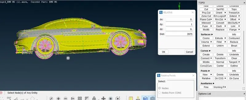
Create point at right side:
Do curve to joint points:
- Topo Deck- points - relative - points - select points. After the points are created join these points from bottom plane by 'create curvesb'
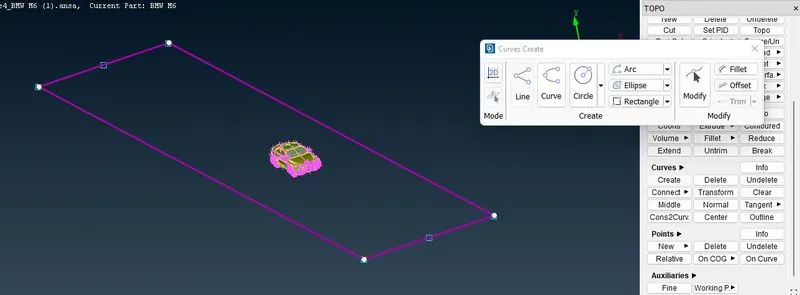
- Once the curves are created for top and bottom then create a surface with help of 'New' option in 'faces'
- Topo - Faces- New -Fitted -will open PID manager window-create new PID -double click on it to create surface on it.
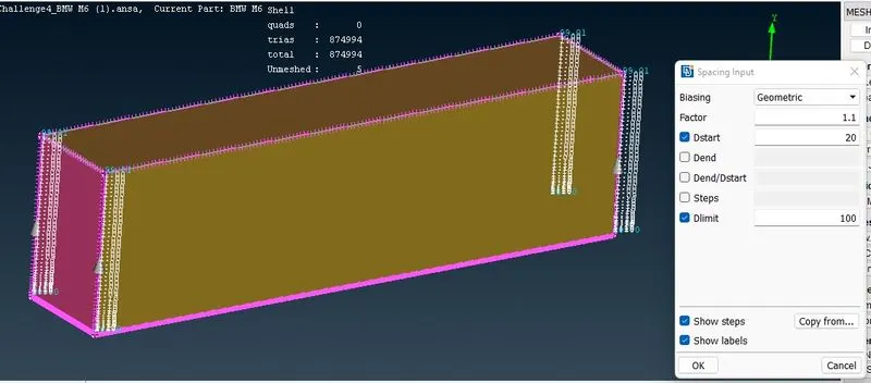
- As the analysis of what happens over the surfaces of car is of importance so the bottom of wind tunnel should have good resolution as compare to the top portion as it relatively at larger distance than botttom. So mesh length of 20 is taken at bottom and 100 for top portion.
- As the front and rear of car are connected with the top and bottom surfaces then the mesh length for this surfaces should vary from 20 to 100 from bottom to top portion. This gradual variation can be achieved using Spacing option from the perimeters section of Mesh deck.
- Perimeters- Spacing -Geometric -factor of 1.1 and d-min of 20 successful application of this will be indicated by upward pointing arrows.
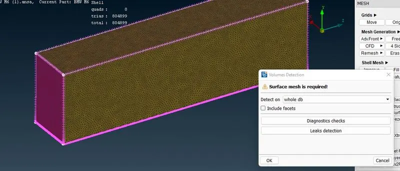
- Mesh is generated by applying Spot mesh for individual surfaces.
Learning outcomes:
- Learnt the complete CFD meshing skill from skratch.
- Performed various topo clean-ups using different tools.
- Understood the need of double cons and removing unecessary triple and single cons.
- The use of symmetry helps in reducing the work time and helps in having accurate results with less work.
- Create surfaces using the reference hot points by using relative points.
- Surface meshing for different components and their varying mesh lengths.
- Using spacing option in surface meshing helps in having varying mesh lengths along the surfaces.
- Using re-construct option to reduce off elements to a level where we can edited it manually.
- Using the mesh modifying tools like move, split and smooth options.
Results:
https://drive.google.com/file/d/1jakXrVGGc_SAuG-dRDfmlFUdqgjrw1sR/view?usp=sharing
Conclusions:
- BMW car model is topo-cleaned and surface meshed appropriately.
- Wind tunnel is created and surface meshed with reference to the car model size.
- Different volumes of the car model is created since th silencer and tyres are not connected to the car body.
- Single volume is created of the car body so that it can be avoided at one go when creating a volumetric mesh.
- Required physics tests can be performed on the wind tunnel volume model after volumetric meshing successfully.