Week 4 Challenge : CFD Meshing for BMW car
Objective :
- To Identifying & cleanup all the topological errors in the given BMW M6 Car model.
- To create a surface mesh.
- To Create a wind tunnel around BMW M6 Car .
- To create a volumetric mesh to perform an external flow CFD analysis simulation.
Introduction :
ANSA :
- ANSA is a Computer-aided engineering tool for Finite Element Analysis and CFD Analysis widely used in the automotive industry. It is developed by BETA CAE Systems. The software is distributed world wide by a number of BETA CAE Systems subsidiaries and business agents.
- ANSA maintains the association between CAD geometry and the FE mesh. This means that the FE meshes are better representations of their geometric parents. Also it is easy to maintain and update any changes in the geometry by simply reworking the updated area instead of recreating the FE from scratch.
- It carries several proprietary algorithms for meshing suitable for both CFD and structural models. ANSA was initially standing for 'Automatic net generation for structural analysis', but the software has gone beyond that very quickly. ANSA has broadly six menus which are used to do various activities those are: TOPO MESH, VMESH ,DECK-SOLVER, MORPH ,HBLOCK.
Different type of modules in ANSA :
- TOPO - Set of tools for Geometry clean-up and for setting up of PIDs.
- MESH - Tools to generate Surface Mesh or 2D Mesh.
- VOLUME MESH - To generate solid or 3D Mesh.
- SOLVER DECKS - Tools based on different solvers such as ABAQUS, RADIOSS ,ANSYS etc.
- MORPH - Advanced tool to capture geometry more accurately while meshing.
Solution procedure :
- For solving we follow the below procedure ,
- Import the CAD model.
- Identifying & cleanup of the topological / geometry errors .
- Geometry check-up.
- Setting-up of relevant PIDs.
- Defining the element size or length.
- Setting the mesh parameters , selection of meshing type and generating surface mesh of the CAD model .
- Resolving the errors in the surface mesh.
- Creating the Full Model Using Symmetry Option.
- Creating the wind tunnel for external flow CFD analysis and surface mesh of wind tunnel.
- Generating volumetric mesh.
- Let us start solving one by one by following above steps :
1) Importing CAD the model :
- To import the CAD model we follow below steps,
Go to file -> open -> browse the location of the CAD model -> select it click on open.
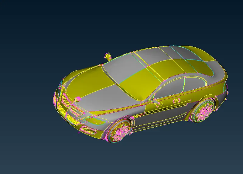
- The model which we have imported opened in ENT mode , we can see the PID mode by selecting PID mode in the bottom layout.The below image is the PID mode of our BMW M6 Car model .
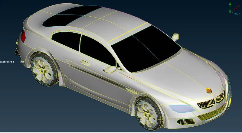
- Now lets see the wireframe mode of our model to see the topological errors more clearly .
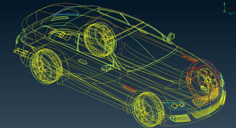
- In the wireframe mode of our model model we can see the errors like single cons , triplecons etc. Let us clear the topo errors one by one.
2) Identifying & cleanup of the topological / geometry errors :
- Before performing any topo clean up , you can observe that the resoution of compenents are not very much good . So to have a better resolution let us first go to mesh deck and decrease the mesh length by selecting the whole model and giving 1mm mesh length .Now you can observe that in the below image the resolution of car is pretty much good .
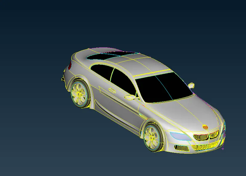
- As we seen that the given geometry has several topological errors, missing faces which are indicated by single cons & triple cons, but for the CFD analysis only the double cons are preferred not even the triple cons are acceptable because it may lead to forming a local volume over there. Let's do a systematic approach to solve this errors and mesh the given model.
- The given car model has a symmetry on a central axis, the best way of approach is to delete the half of a model and eliminate the topological errors and then meshing on one side & finally perform the symmetry to get the full model again.
- In the below image you can observe that we have deleted only body part and left the logo as it is , because logo is not symmetrical where as whole body is symmetrical i.e., same on both sides .
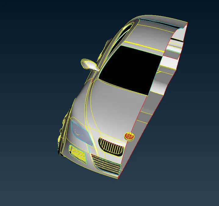
- Here , the main aim is to create whole car inside part as one volume and as tyres and silencer are not attached , then each of them forms one volume means 4 tyres and two silencers 2 volumes and another volume forms between car and wind tunnel ,which is the volume we needed .So we delete all other volumes and keep the final volume as we ae doing external flow analysis .
- Initially, there were many errors , each of them should be rectified systematically by one after other. The errors are being corrected by selecting the individual features of the car like grills, lights, wheels, logo, windshield , side grill etc., seperately.
- Here, also we are much concerned about outside features of the car and not about inside features .We have to modify all the features such that we get whole car inside part as one volume .
- So to have the whole model as single volume we should have only double cons and even wit double cons we should not have a feature closed on all sides ,it may lead to form a seperate local volume over there .
- Here , we should on have single cons on that side of the car where we need to do symmetry , so that we can do topo there after symmetry such that there also we will have double cons finally .
- So we will delete the surfaces which are not necessary and causing an error or leading to cause a local volume .
- If you are not clear about the selection always zoom in and select the right surface . Also use wireframe mode for proper selection (Cntrl + shift or directly turn off shadow mode ) .
- Here we always shift between PID and entity mode depending upon the suitability to solve particular problem .
- Here in all the cases , depending on the situation we use any one of the tools like project , extend ,cut , topo , intersect ,new coons etc. to clear topo errors .
- So by following above points , let us select one by one and clear topo errors .
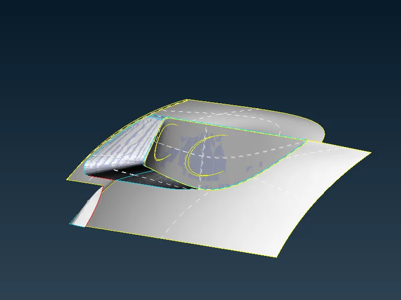
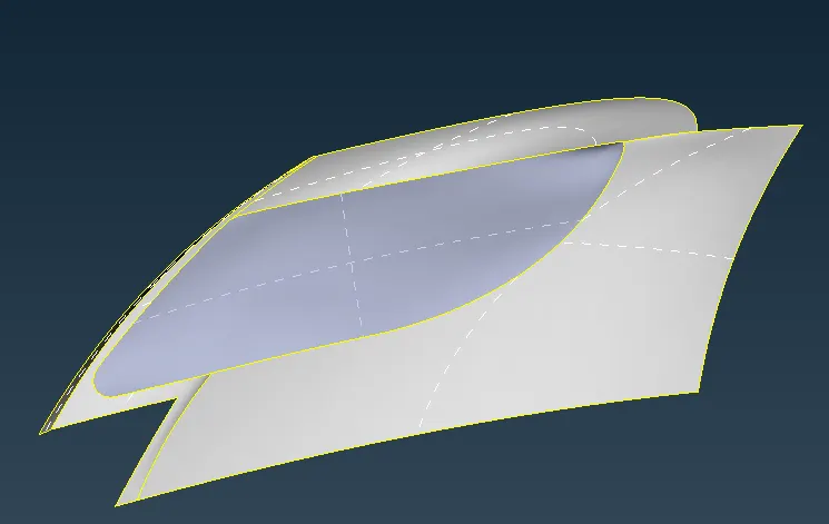
a) Front Light :
Before correction :-
After correction :-
b) Grills :
- For an External flow analysis we dont need a volume of the feature or parts.
- Therfore deleting the thickness of the part & Unnecessary faces to get rid of single cons & triple cons in this feature model.
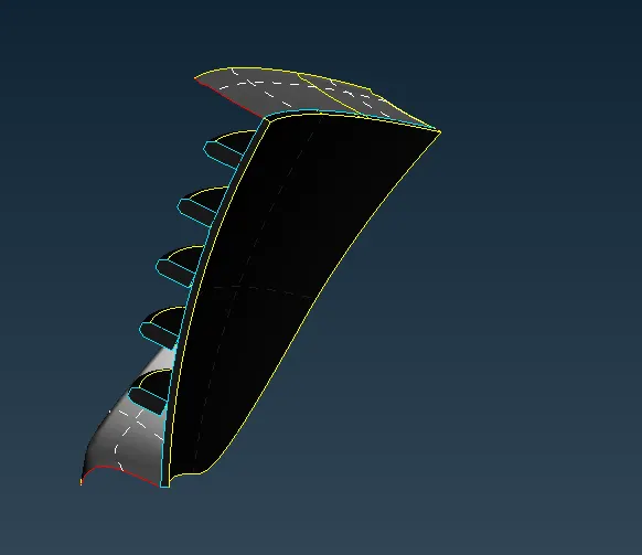
Front central bottom grill :
- The below image is the front central bottom grill before topo cleanup.
- The below image is the front central bottom grill after topo cleanup .
Front left grill :
- The below image is the front left grill bottom before topo cleanup .

- The below image is the front left grill bottom after topo cleanup .
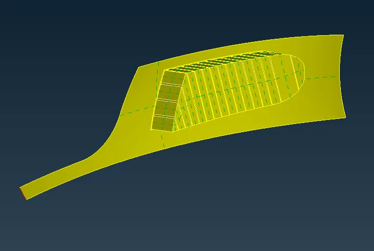
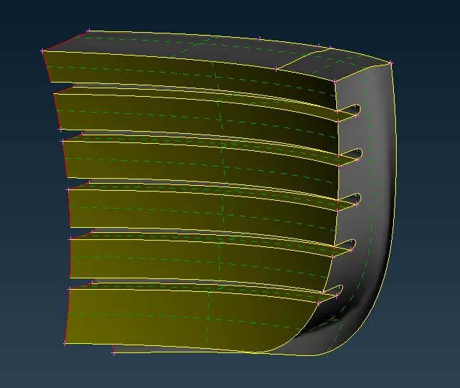
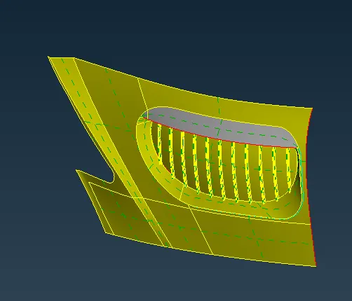
Front central top grill :
- The below image is the front central top grill before topo cleanup.
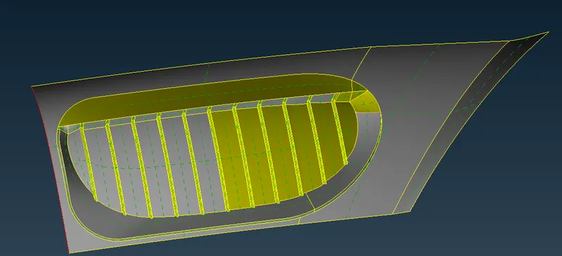
- The below image is the view of front central top grill from inner side after topo cleanup .
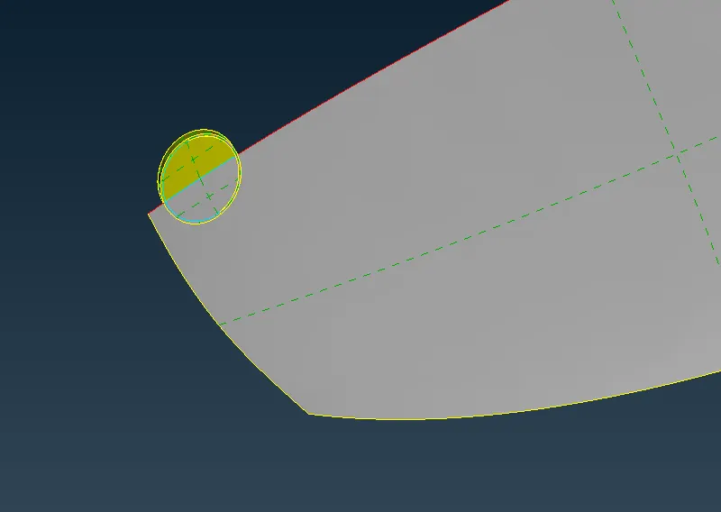
c) Logo :
Before correction :-
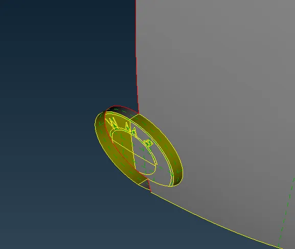
- For logo we delete all the inside surfaces and keep it as hallow as not to create any local volume over there .
- The below image is of the logo before topo cleanup.
After correction :-
- The below image is of the logo after topo cleanup from inside.We can see that all the triple cons have been cleared .
d) Front and side windshield/windows :
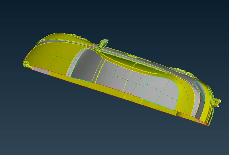
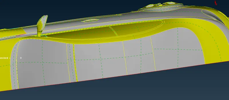
- The below image is of the front and side windshield before topo cleanup.
- Triple cons are appearing in a window where the edge is shared by three surfaces.We need to delete extra surfaces ,so that we will have double cons all over .
- In the below image we can see clearly the thickness of window which we need to delete .
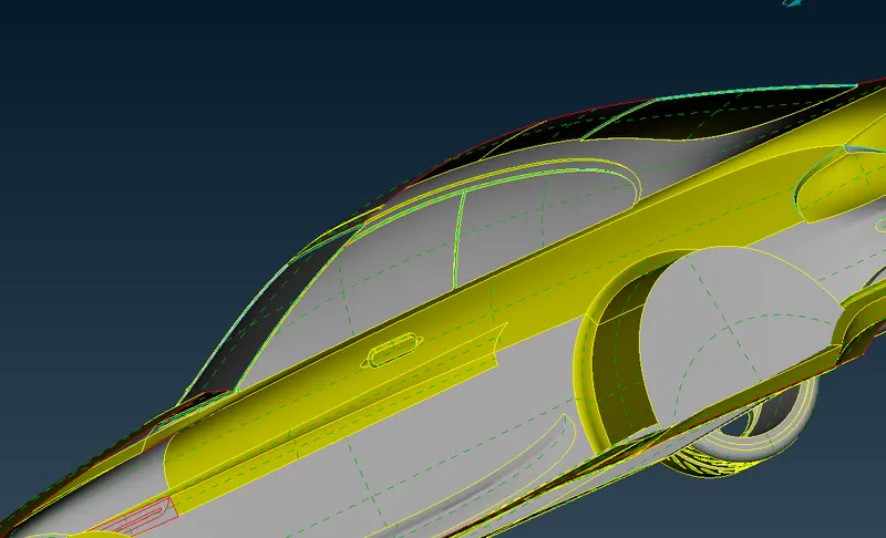
- The below image is of the front and side windows after topo cleanup. All the triple cons near windows has been cleared ,we can see only double cons.
e) Side style feature :
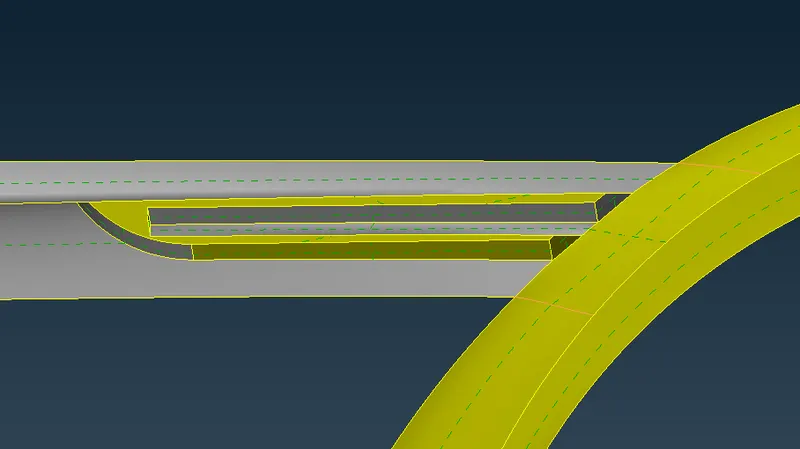
- For an external flow analysis we dont need a volume of the feature or parts.
- Therfore deleting the thickness of the part & Unnecessary faces to get rid of single cons & triple cons in this feature model.
- Always delete the unnecessary hot points using delete under hot points.
- In the following image we can see inner view of the feature before topo cleanup .
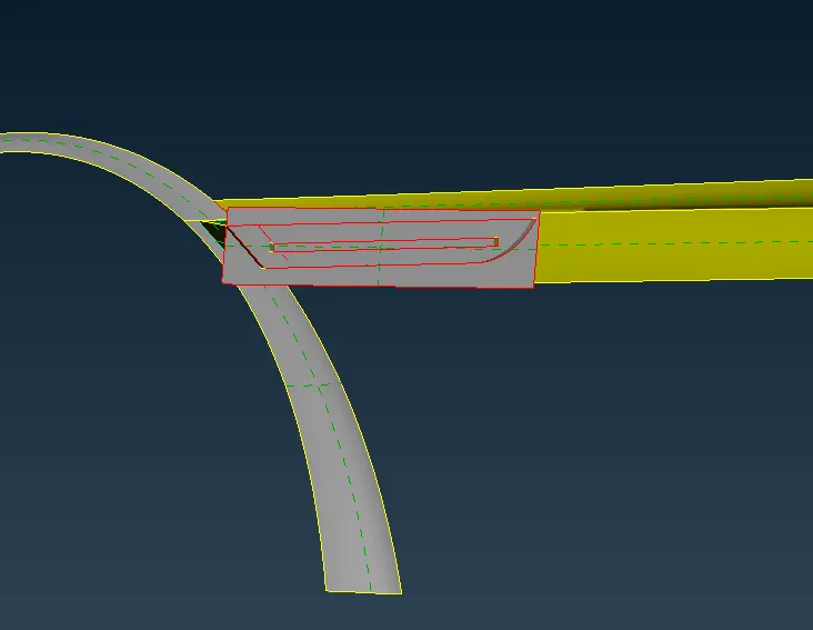
- The following image is the exterior view of the feature after topo cleanup .
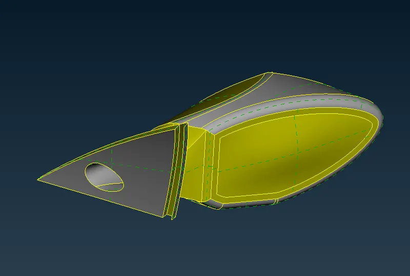
f) Optical rear view mirror :
- In the below image we can see the thickness part of mirror clearly ,which we need to delete .
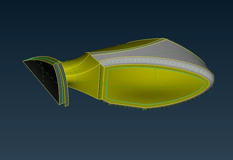
- The below image is of the mirror after topo cleanup .
g) Rims and Tyres :
- The below image is of the rims and tyres before topo cleanup.
- Here we delete all the triple cons and single cons and make the whole tyre and rim to form only one volume .
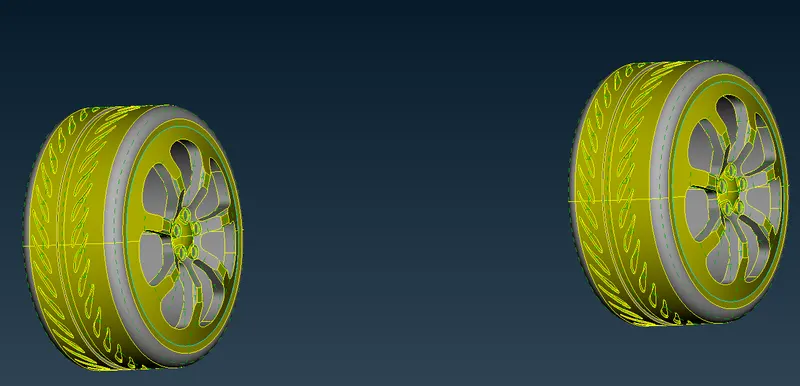
- If you do't see any triple cons in your particular model , that means that model is hallow from inside i.e., it don't have any attached surfaces from inside , which means the model visible has only one common volume .
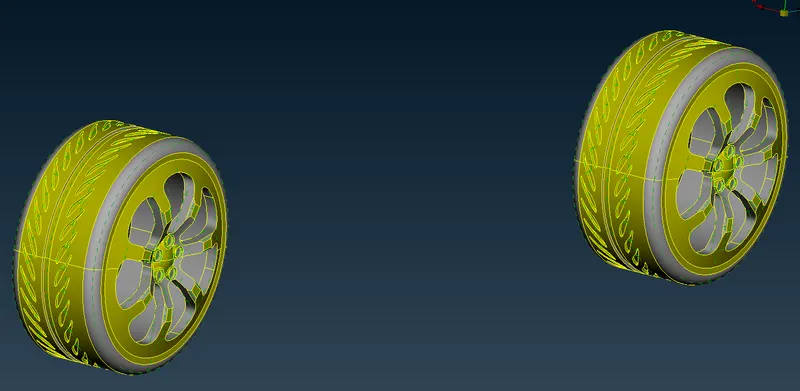
- The below image is of the rims and tyres after topo cleanup.
h) Body part :
- The below image is of the body part from inside before topo cleanup.
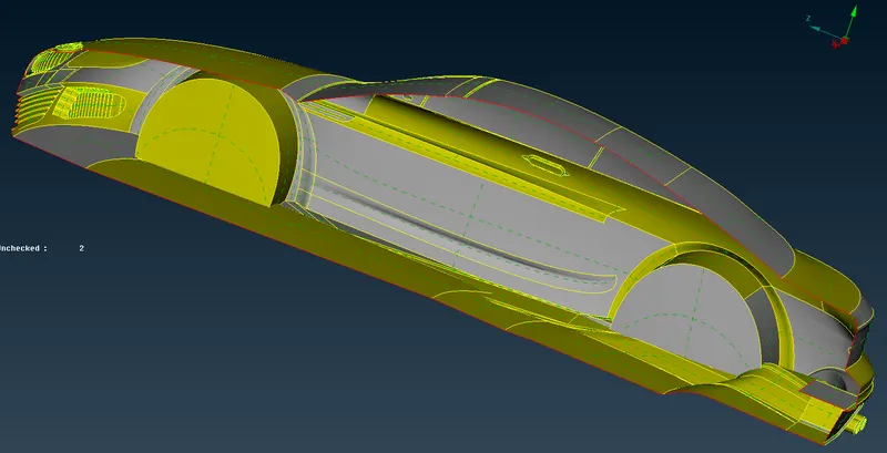
- The below image is of the body part from outside before topo cleanup.
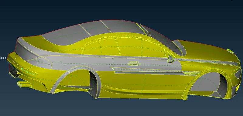
- Here For body part we delete all the extra surfaces extruded through the wheel .
- If you delete any surface and want to create a new surface in place of old , you need cons .So , for that inorder to have inorder to have foot prints of deleted surface if in an empty space , we will use con2curve before deleting for this ,by selecting this and selecting con it creates a curve over there for reference .
- There are a lot of approaches to solve any error .The thing is we have to select upon our convenience .
- We have to follow any approach applicable , but final thing is to delete all the unnecessary cons and surfaces , such that it doesn't create any local extra volume over there .
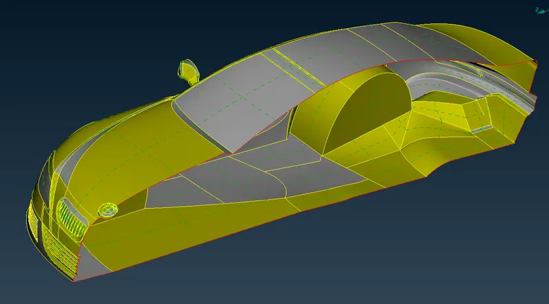
- The below image is of the body part from inside after topo cleanup.
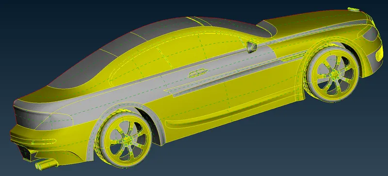
- The below image is of the body part from outside after topo cleanup.
3) Geometry check-up :
- After cleaning-up all the topological errors , the geometry is checked using geometry checks under checks manager.
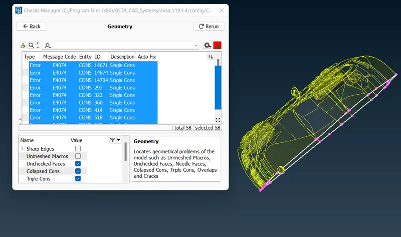
- We will see only the single con errors where we would expect on one side of the body where we do symmetry .
- The below image is the final view of our model after topo cleanup.
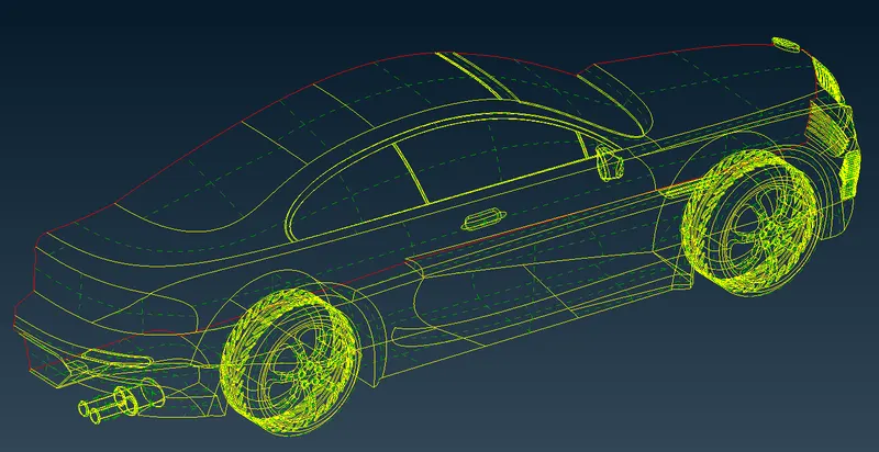
- So we can conclude that all the errors have been corrected & the model is ready to be meshed.
4) Setting-up of relevant PIDs :
- In this step we assign the PID for different parts and give a name and colour to differentiate between the components and ease up the working on the components individually.This is also done to specify names to different boundary conditions for various parts.We need to activate cross hatches before setting-up PIDs.
- If you open properties manager at the top , you will have some default PID's which are assigned. We have to create new PID's to assign for our components. Inorder to create new PID , right click on properties manager -> click new -> then select pshell -> then again select pshell -> then give name in the popup box -> then ok .You can change the colour by double clicking on the colour box -> then ok .
- In the similar way create PID for all the components.
- Then next thing is assign these PID's to the components of the geometry .
- To apply , we select /click on the PID to apply in the PID manager -> then right click on it -> then click on apply -> then in the geometry select the cross hatch of the surface you want to assign -> then middle click . In the similar way we have to apply PID's we have created . To give the PID we select with the different type of selection available to select the exact surface needed.
- Then after assigning the PID , delete the empty orginal PID's which has no components assigned by using compress .
- In the below image you can see that list of PID's we have assigned.
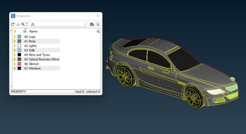
5) Defining the element size or length and setting the mesh parameters & creating the surface mesh and resolving the errors in the surface mesh :
- Here we perform all the three tasks ,defining the element size or length and setting the mesh parameters, selection of meshing type and generating surface mesh of the CAD model and resolving the errors in the surface mesh by selecting each PID one by one and perform above tasks .
- Before meshing we have to give quality criteria .Here we select openFoam solver deck,so that we get the quality criteria of that solver .
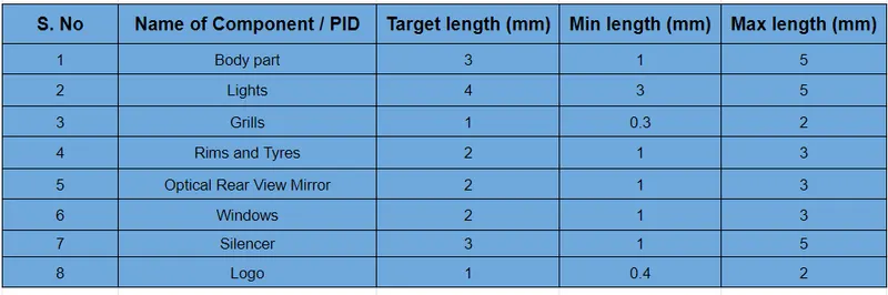
- Here as we have different surfaces , we will use different quality criteria for different surfaces , we will change mesh length as per our surface complexity and surface size . If surface is small we have to use smallest target length , if larger we use accordingly .We set the element lengths accordingly, as a fine mesh for every element would be time consuming & will be computationally Expensive.
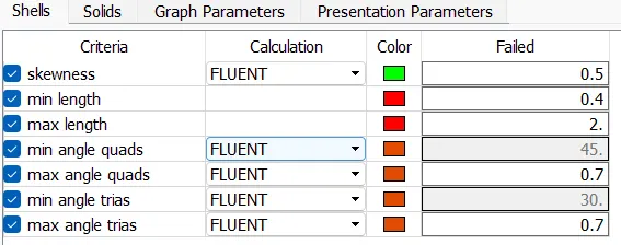
- Here we give the below different quality criteria (min length and max lenth ) for different components as shown in figure .
- But before doing these tasks , we will follow following steps so that we don't have any off elements later in meshing stage . We will try to remove small surfaces that are smaller than our min mesh length , we will directly remove the cut ,which are unnecessary if found small. If that cut or feature line is necessary , if we remove that cut it may loose shape , in that type of scenario me make a cut at another location and remove the orginal cut causing problem , so that there is not much change in geometry .The new cut should also satisfy the minimum length criteria . If not able do cut or that feature line is very important to maintain shape of geometry ,then we will reduce the min length value so that ,our element length would not fail.By following these steps we will evaluate all the PID's / components .
- By following these processes we completed evaluating our model and next thing is to do meshing .
- In the below image we can see the logo before evalutation.
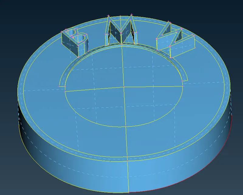
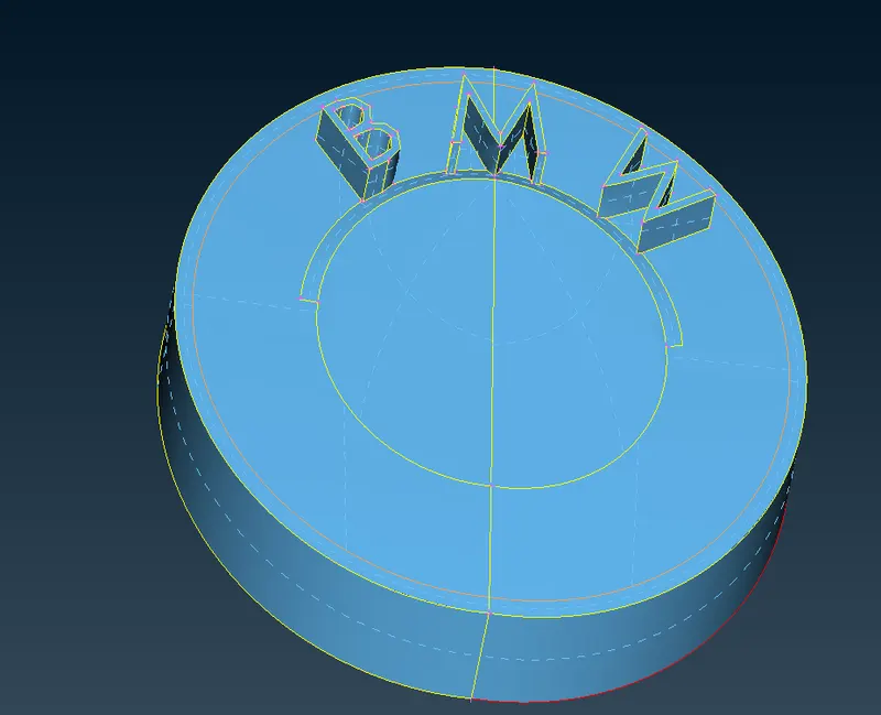
- In the below image we can see the logo after evalutation.We have removed the sharp and small surfaces which cause error for min length and created new surface on the logo and also for letters .
- We start meshing from smallest component to larger component one by one .
- We mesh the body PID last because as t is attached to lot of other PID's if you mesh it first and mesh other PID attached to it later it may lead to erase of mesh of body at that location .For this reason we mesh the body PID last .
- We isolate each component/PID and give above quality criteria(target, min and max length ,skewess etc. ) in quaity criteria and then in mesh parameters .We also select skewness and give value as 0.5 for all the PID's and also min angle trias as 0.7 .You can see the quality criteria given in the below image , we change only min length and max length based on the PID.We give the values for quality criteria as in the above table .
- Here then we will select the Meshing algorithm and then finally we perform meshing.We follow below steps for that ,
-
Go to Mesh Generation -> spot Mesh -> tria -> drag and select the required model -> click on the scroll button/ middle mouse button on mouse to mesh (or) we can directly select visible under drop down menu of spot mesh instead of drag and select the entire model after seperating them by using NOT .
- After meshing we remove the off elements of that particular PID byselecting the hidden mode .
- In the hidden mode you can see the off elements with the colour you have selected for that quality criteria in the quality criteria menu .
- After meshing we will see some off elements , we can remove most of them by using reconstruct under shell mesh ,and further if you have any off elements we have to go the location individually and clear that off element .
- When you have off elements , you can go to topo mode to see clearly. If possible to do it in mesh mode do it ,so that you will not loose mesh .
- If you want to remove any con it's better to remove it in the mesh mode ,so that mesh will not erase .If you go to topo mode and remove any con or surface or create a new surface the mesh will be erased .So if possible it's better to remove it in the mesh mode .
- We can remove the remaining off elements by removing mesh improvement tools . we can use split , smooth ,paste etc.We have to use mesh improvement tools depending on the situation .You can view better by using neighbour 1st level .
- We have to use move grid only if necessary , by using it may lead to change in shape of geometry as we move boundary grids.
- By following above steps start we start meshing with logo and then clear off elements ,such that the off element count goes to zero (0).
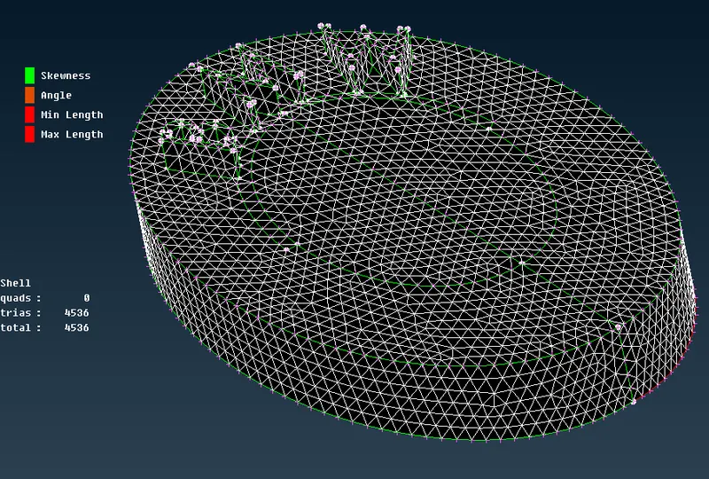
- In the below image we can see the logo PID with no off elements .SO let us mesh another PID .
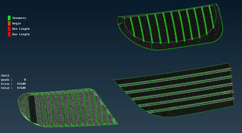
- In the below image we can see the grills PID with no off elements.
- In the below image we can see the windows PID with no off elements.The off elements will be cleared automatically after using reconstruct .
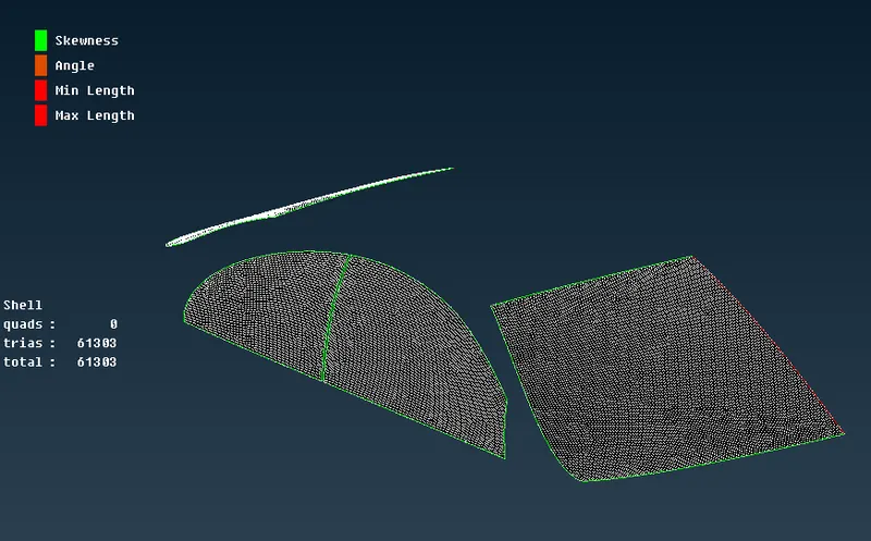
- In the below image we can see the lights with no off elements , we clear some off elements by using mesh improvement tools .
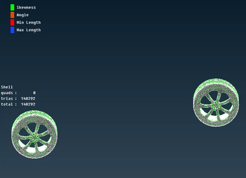
- In the below image we can see the rims and tyres with no off elements. Here we get some skewness and min length off elements .We remove them by removing the cut ,but before that we create another cut at the same location to compensate for the removing cut at another location , as not to loose the shape of geometry .
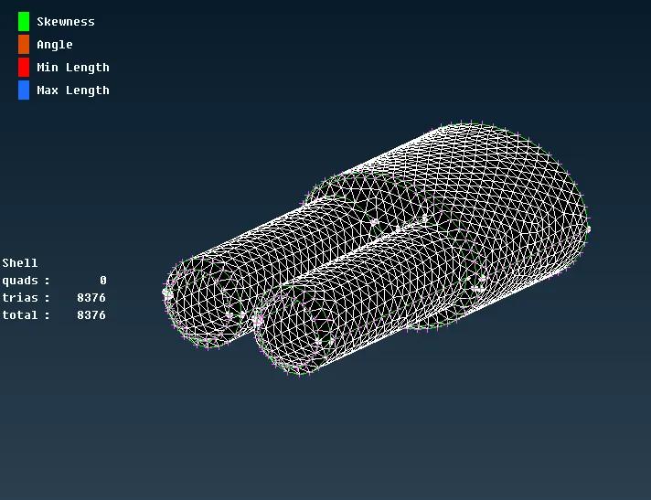
- In the below image we can see the silencer PID with no off elements.The off elements will be cleared automatically after using reconstruct .
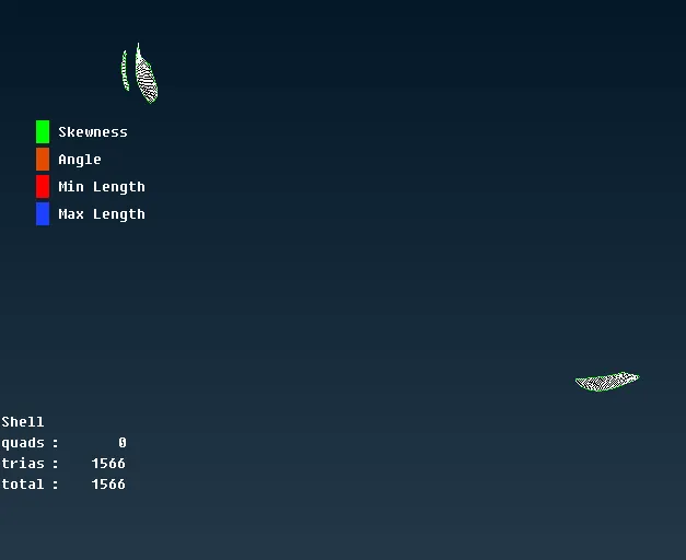
- In the below image we can see the optical rear view mirror PID with no off elements.All the off elements have been cleared directly after using reconstruct .
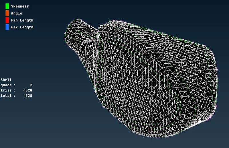
- As there is one PID left i.e., body .As it attached to all other PID , there is possibility of erase of mesh at the interface .So to give length , we select length under the perimeters, and select all the perimeters or cons ,and then deselect all the cons that are at the interface of body and other PID .You can select clearly by using wireframe mode and then give the length.We give only in the perimeters . Even if you give length in macros , there is a chance of mesh to be erased .
- If you select the perimeters attached to other PID , it may lead to erase of mesh at that location .
- Here if you don't give length by selecting the required perimeters and mesh directly by giving 3 mm in the mesh parameters ,then whole model will be meshed with 1mm as element length, as we gave 1mm at the start for resolution .So it is necessary to give length in perimeters .
- We will give length by making all PID's visible , this is done to select properly the required perimeters such that the mesh of other PID's is not erased .
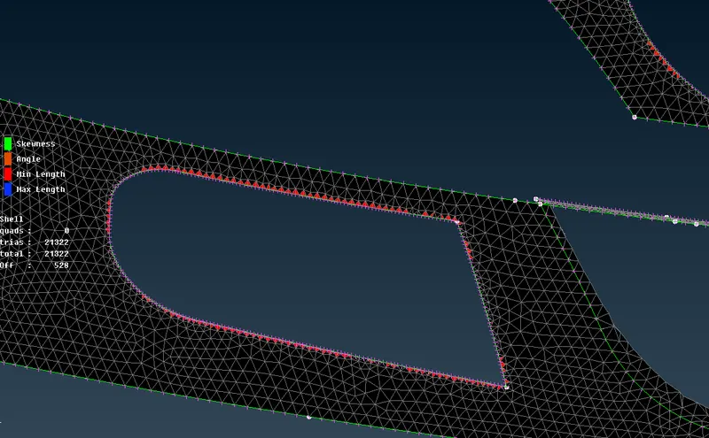
- Here in the body PID if you see ,we will have min length error , those can be reduced if you give length by selecting and increase the length by selecting those common perimeters of body and other small min length PID .As we have not selected those perimeters while giving length for body PID as not to erase mesh , the min length of other PID attached is small definitely ther will be min length error exists at that location.
- All those visible errors of minimum length can be overcome by decreasing the element length in the quality criteria and the errors related to skewness can be corrected by a combination of mesh improvement tools .
- In the below image we can see the whole model with no off elements.All the off elements have been cleared.Now next thing is to do symmetry .
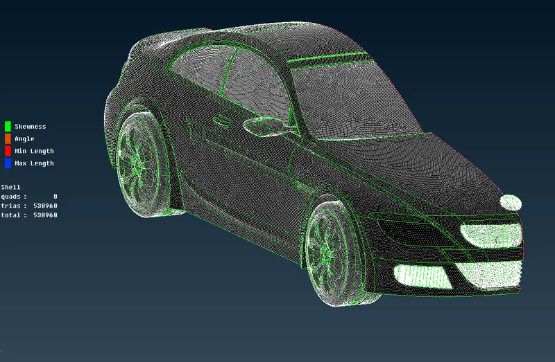
6) Creating the full model using symmetry option :
- Here we Perform the symmetry to get other half of the model .
- The Second Half part of the model which is symmetric about the centre line is created by using the Function 'Transform'.
- Transform:- This function is used to Translate, Rotate, scale, mirror & Relocate an Entity.The selected Entity can be moved to a new position or copied the same at a new location.
- Transform feature can be selected from the utility browser and it asks for what to be performed in the same function such as move, copy and link. In copy & move 5 features can be observed.
- As we are performing mirror, go to symmetry after selecting copy and use 3 point to create a symmetry about a centre line.
- The 3 points should lie on the line about which the symmetry is required & for accurate result the three points should be at different locations three dimensionally.
- Transformation Option: Asks whether to Create a Seperate PID or Retain in the same PID, also whether the offset is required for the new parts.We keep it to default as not offset or change of PID is needed.
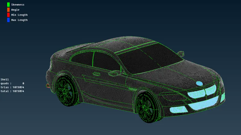
- Topo or paste feature is applied to prevent single cons at the centre and remesh if any mesh is lost. In the above image you can see the complete model after performing symmetry .
- Before creating we perform geometry checks for full model ,we find that there are no errors .We can observe the same in the below image .
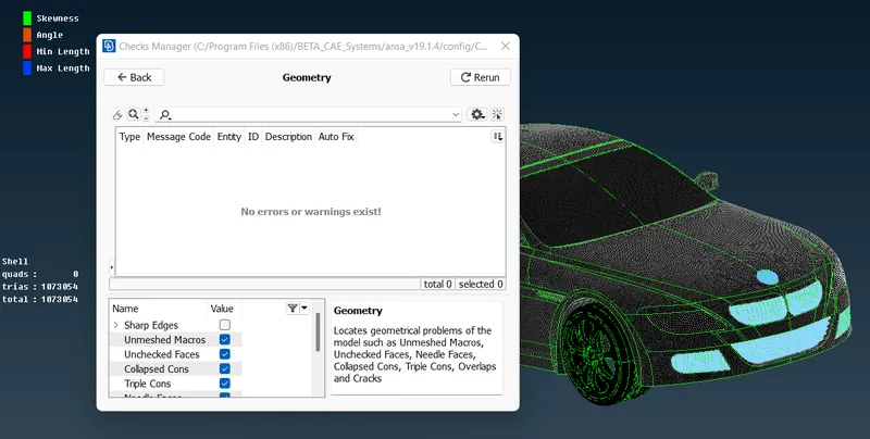
- The below image is the final view our model after performing the symmetry. Then next thing is to create wind tunnel and perform volumetric mesh .
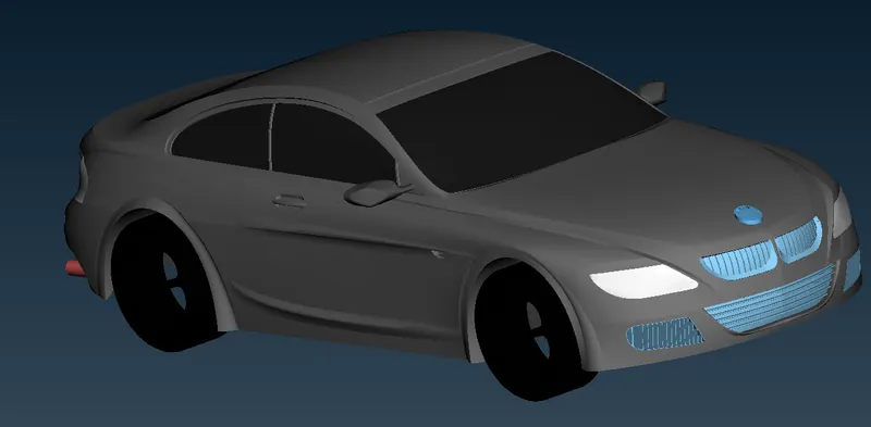
7)Creating the wind tunnel for external flow CFD analysis and surface mesh of wind tunnel :
- To perform external flow CFD analysis a wind tunnel has to be created around the car. It is created in TOPO mode as a Rectangular box. The Dimensions of the wind tunnel is also important so as to capture the exact flow around car. The dimensions are as follows:
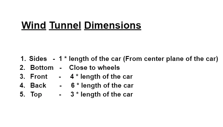
- Inorder to create a Wind tunnel, first create a point by selecting relative at 80mm from centre by selecting a hot point at a distance of 80 mm to bottom .
- By taking that point as reference , we create anotheer point to front of car at a distance of 654 + 4* 1300 = 5854 mm (654 mm is distance from centre to front of car and 1300 mm is length of car ).
- Then we create another point at the back at a distance of 610 + 6* 1300 = 8410 mm (610 mm is distance from centre to back of car and 1300 mm is length of car ).
- Then we create another two points on both sides of car , with the help of front and back of car , which we have created , such that we can join all the four points with the help of curve and create a surface there with the help of 4 curves .This completes creation of bottom part .
- Then we create top face by using offset at a distance of 375 + 3* 1300 = 4275 mm (375 mm is distance from centre to top of car and 1300 mm is length of car ).
- Now using these two surfaces we create new surfaces on all sides and close the volume , such that it forms a wind tunnel .
- Now we create and assign PID's for the wind tunnel walls.In the below image we can see that PID's are created and assigned .
- The below image is the wireframe mode of wind tunnel we have created .
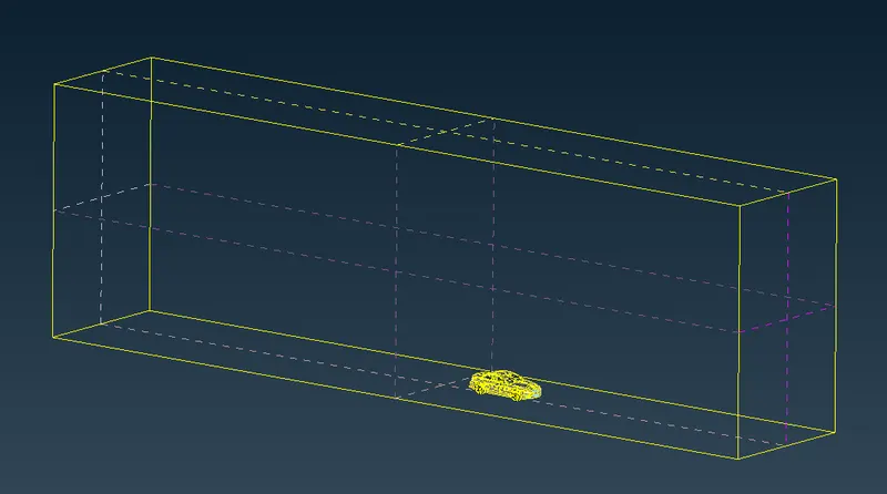
- Next thing is to do surface mesh to the wind tunnel .
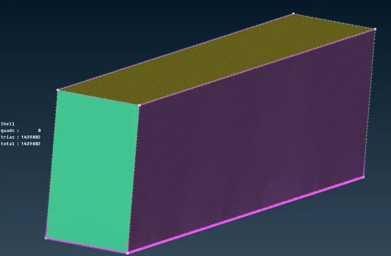
- Now that the wind tunnel has been modelled, it has to be surface meshed first, such that the mesh size gradually grows from top to bottom.
- If we have refined mesh ength at the top ,then we will have lot of cells and lot of computational effort is required to solve .So , we give varying mesh length .
- This can be done by using the spacing option under perimeters in mesh utility menu.
- choose geometry biasing option & set the dmin value as 20 and dimit value as 100 and facot as 1.1 and select all the four vertical perimeters.But before that we surface the top part by giving a length of 100 mm and bottom part with a length of 20 mm .
- Then generate surface mesh. In the below image we can see that the mesh length is varying and increasing from bottom to top .
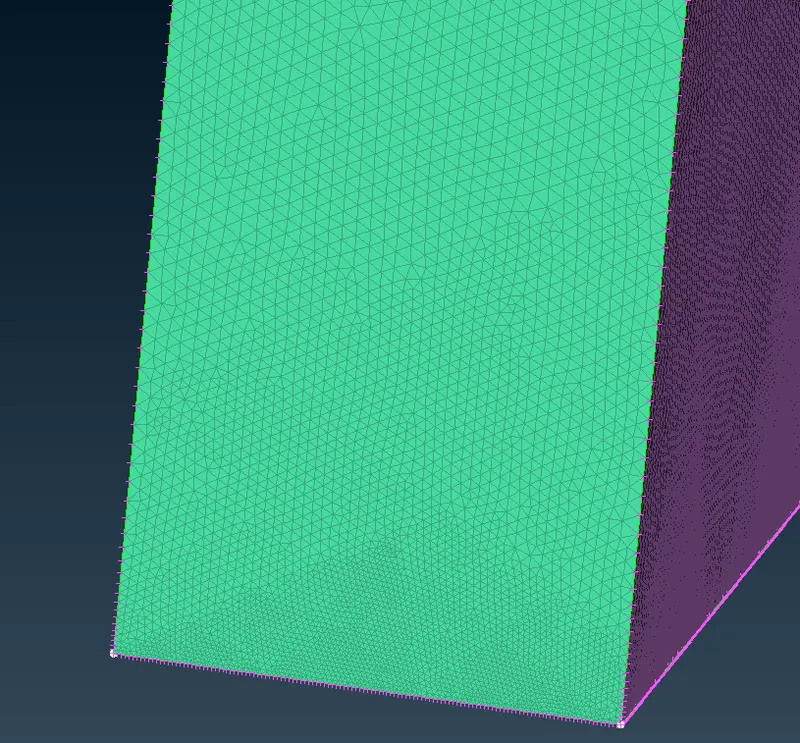
- In the below image we can see that the surface mesh is completed successfully for whole model and wind tunnel and mesh length is varying,increasing from bottom to top .And also there are lop of elements .
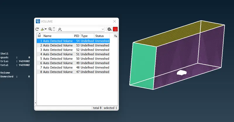
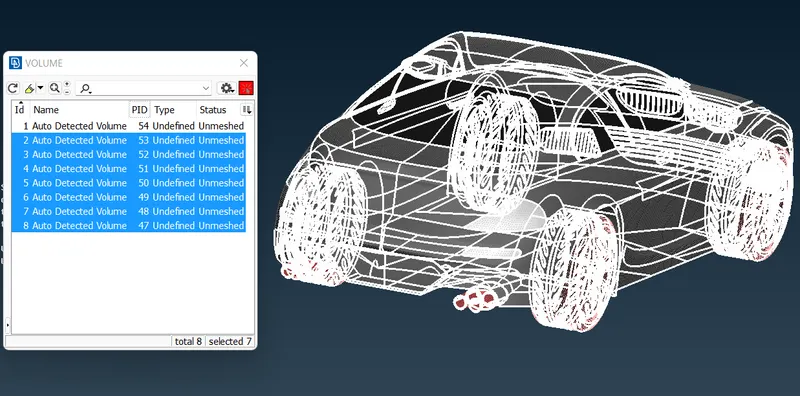
- Now as surface mesh is completed ,next thing is to do volumetric mesh . To do volumetric mesh we have to define volumes . Then ANSA auto detects volumes , in that we keep only the volume between car surface and wind tunnel , and as tyres and silencer are not attached , then each of them forms one volume means 4 tyres and two silencers 2 volumes which ae the volumes we delete .We keep the first volume as we are doing external flow analysis .
- In the below image we can see the required volume between car surface and wind tunnel .
- In the below image we can see the volumes which are not required and needs to be deleted .
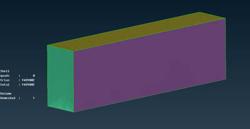
- Now as there is only one volume left ,for volumetric mesh to be done we use tetra CFD under unstructured mesh .But as the volume created by wind tunnel is very large and as it is of lot of meters and our mesh length is in still mm , it will create lot of elements ,So it will take lot of time to finish volumetric mesh .So we can guess the volume created will be hallow inside of car and other parts where the volumes we deleted and whole other location will be filed with cells .So we cwill stop here with surface mesh as volumetric mesh further takes a lot of computational effort .
- In the below image we can see the final mesh before performing volumetric mesh .
Learning outcome:
In this process of working on this project we have learned how to,
- Identifying & cleanup of the topological / geometry errors .
- Geometry check-up and setting-up of relevant PID's and defining the element size or length .
- Setting the mesh parameters and quality criteria, selection of meshing type and generating surface mesh of the CAD model .
- Use Quality criteria tool & also learnt various options under the shell parameters such as Skewness, min length, max length, max angle &min angle, etc.
- Resolving the errors such as skewness, min & max lengths using various tools.
- Perform symmetry, translation, rotation & scaling option under Transform Tool.
- Set-up Wind Tunnel as per given dimensions for external flow CFD analysis and surface mesh of wind tunnel .
Conclusion :
- The imported CAD model of BMW M6 is Topologically Cleaned & Corrected all the feasible surface errors to perform external aerodynamic analysis.
- Surface mesh is generated with the required element size.
- Reconstructed the mesh as per the mesh quality required at Corners & at Intersection of edges.
- Worked with the errors occured in the Mesh.
- Created a wind tunnel For external aerodynamic analysis.
Google drive link for challenge file folder :
https://drive.google.com/file/d/10jyTZLeniU4ibJjR5Dq_R2y4rkbSr0DL/view?usp=sharing