Creation of 1D element in hypermesh
Objective:
To create 1D elements on the following component with given cross-section and DOF.
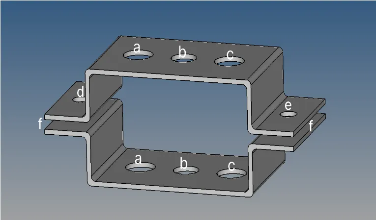
Given Cross Section of the elements along with the position where we need to fit those elements.
Rod element: - with only translational DOF and RBE2 link at (a)
Cross-Section: BOX- Dimension a= 12 mm
Dimension b=10 mm
Thickness t= 0.75 mm
Beam element: - with all DOF and RBE3 link at (b)
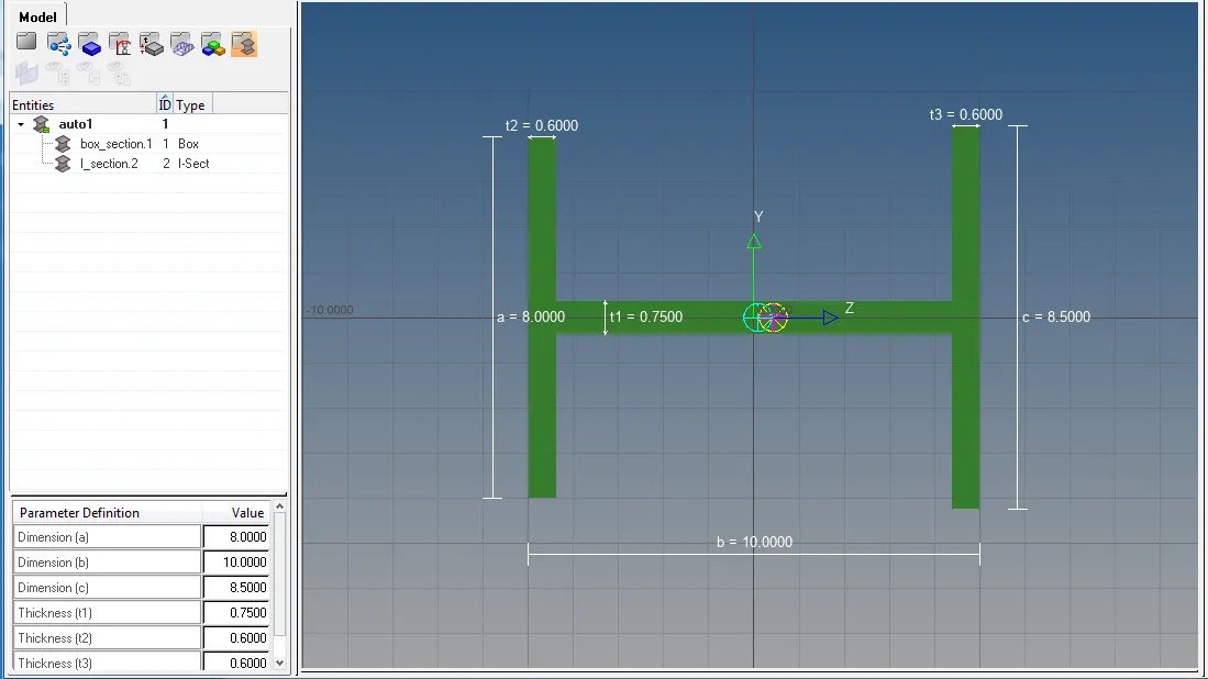
Cross-Section: I Section- Dimension a= 8 mm
Dimension b= 10 mm
Dimension c= 8.5 mm
Thickness t1= 0.75 mm
Thickness t2= .6 mm
Thickness t3= .6 mm
Bar element: - with only x and y DOFs with RBE3 link at (c)
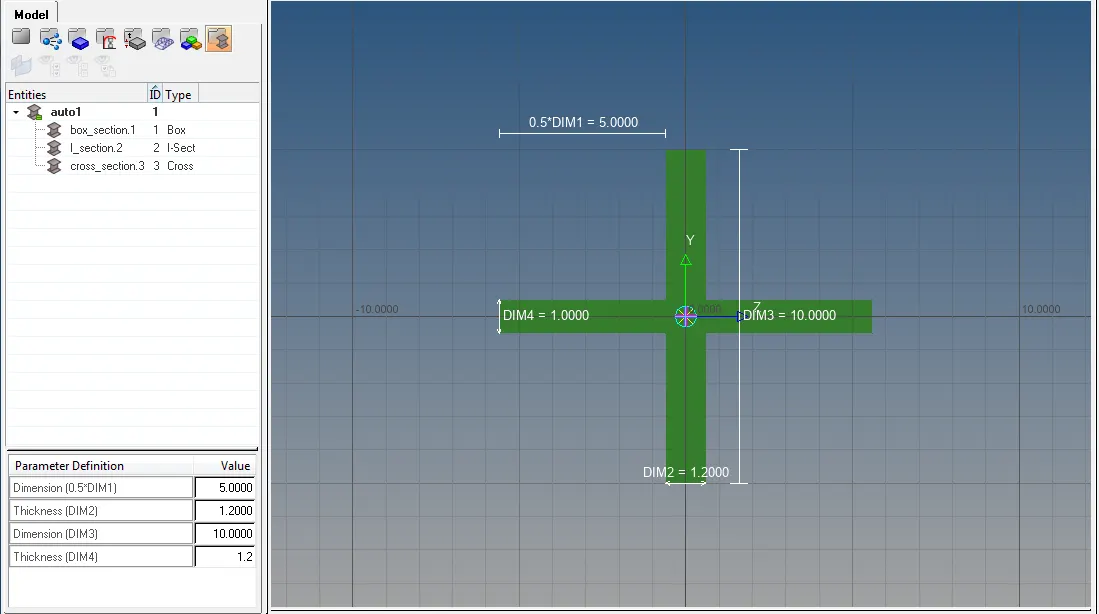
Cross-section: CROSS section- Dimension DIM1= 5 mm
Thickness DIM2= 1.2 mm
Dimension DIM3= 10 mm
Thickness DIM4= 1.2mm
Apply the mass of magnitude 10 with RBE2 link at (d) & (e)
Join the two components with spring elements
Procedure:
- Geometry is imported by going to Tool bar>Import Solver Deck>Import Geometry>File type>IGES>Location where the file is saved.
- Now we do not need bracket wireframe therefore it can be deleted by going to Model>Component. Left click on Bracket_Wireframe>Delete
- Now we have to extract the desired mid surface for the two brackets separately. That can be done by going to Menu pages>Geometry>mid surface. Now the mid surface can be extracted by four ways. To select one, go to extraction option and select offset. Then go to auto extraction>surface. Select the upper bracket and click extract.
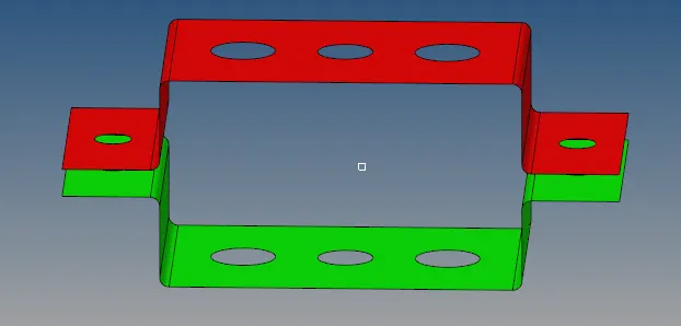
- Then go to feature tree and change the name of the middle surface to Bracket_1 and assign red colour to it.
- Extract the mid surface for the lower bracket by following the same procedure and then go to feature tree and change the name of the middle surface to Bracket_2 and assign green colour to it.
- Delete the components PARALLEL_BRACKET_BODY_0 and PARALLEL_BRACKET_BODY_1 from feature tree.
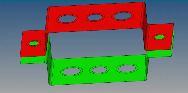
- Following mid surface are extracted from the given components.
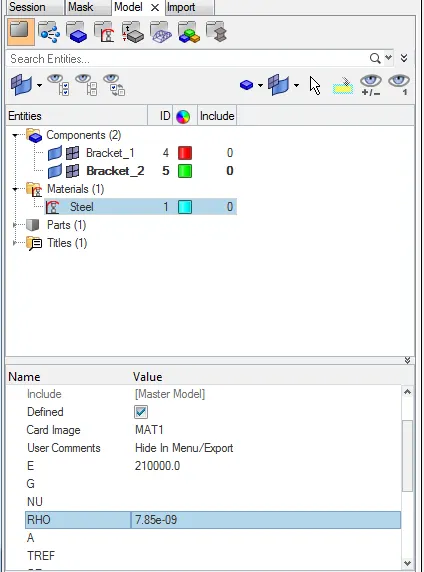
- Now we have to assign material and property to the extracted mid surfaces. For that, go to Feature tree>Entities>Click right mouse button>create>Material. Name the material as steel. From entity editor, provide the necessary properties such as young modulus (E), Density (rho) to steel.
- Now in order to assign properties to both surface, go to feature tree>Entities>Right click of mouse button>create>property. Name it as Bracket_1. Assign Red colour to it. From entity editor, assign material, card id and thickness as Steel, PSHELL, 2.0 respectively. In a similar manner, properties can be assigned to bracket 2 and for bracket 2, keep the thickness as 2.5mm.
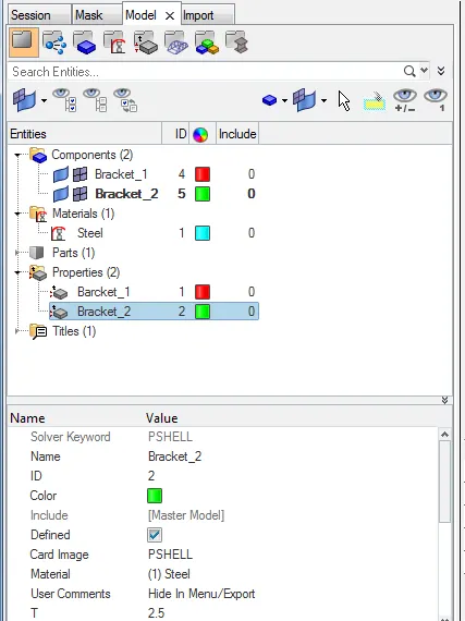
- Assign the corresponding properties to Bracket_1 and Bracket_2.
- Now we have to do meshing on both the surfaces but before that provide washer splits with the offset value of 5mm to every hole.
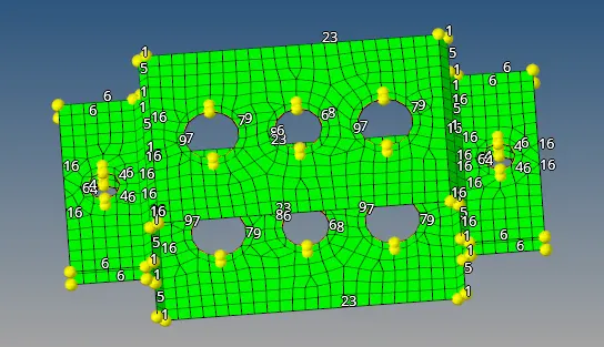
- Now for meshing, Go to menu pages>2D>auto mesh>Surface. Select displayed surfaces and set element size as 8 and mesh type as mixed. Then click on mesh. Following mesh is obtained.
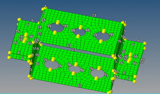
- Now the number of nodes at different holes is matched with the number of nodes at corresponding washer lines so that the mesh can properly capture the region around the holes.
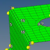
- Still the mesh is not properly capturing the surface around the fillets. To resolve this, increase the mesh density from 1 to 3 around every fillet.
- Now to create RBE2 link with transitional dof at location (a), go to Menu pages>1D>rigids. Here select ’multiple node’ and ‘calculate node’ and then select dof1, dof2, and dof3. After that create nodes around the holes at (a) on both surfaces and click on create.
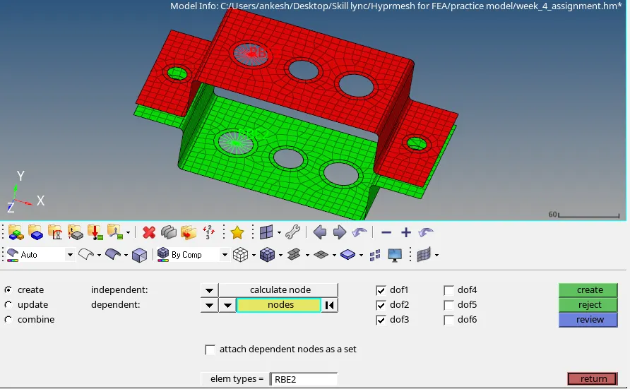
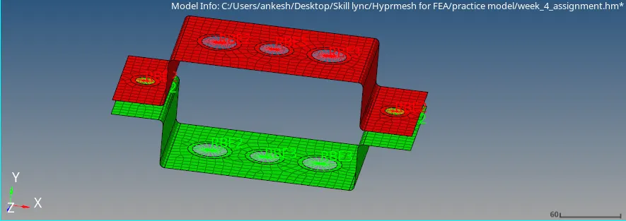
- To create RBE3 link with all dof at (b), go to Menu pages>1D>rbe3. Here select ‘node by path’ and ‘calculate node’ and then select dof1, dof2, dof3, dof4, dof5 and dof6. After that create nodes around the holes at (b) on both surfaces and click on create.
- To create RBE3 link with x and y dof at (c), go to Menu pages>1D>rbe3. Here select ‘node by path’ and ‘calculate node’ and then select dof1, dof2, dof4 and dof5. After that create nodes around the holes at (c) on both surfaces and click on create.
- To create RBE2 link with all dof at location (d) and (e) go to, Menu pages>1D>rigids. Here select ’multiple node’ and ‘calculate node’ and then select dof1, dof2, dof3, dof4, dof5 and dof6. After that create nodes around the holes at (d) and (e) on both surfaces and click on create.
- To create BOX cross section for Rod element at (a), go to Menu pages>1D>Hyper beam>Standard section. Here select standard section library as Hyper beam and Standard section type as thin walled box and click on create. Enter the given dimensions of the cross section
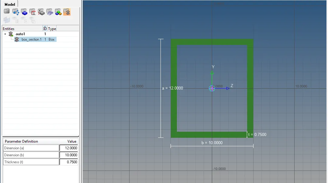
- To create BOX cross section for Rod element at (a), go to Menu pages>1D>Hyper beam>Standard section. Here select standard section library as Hyper beam and Standard section type as thin walled box and click on create. Enter the given dimensions of the cross section
- To create CROSS cross section for bar element at (c), go to Menu pages>1D>Hyper beam>Standard section. Here select standard section library as Optistruct and Standard section type as cross section and click on create. Enter the given dimensions of the cross section.
- To create property for rod element, go to feature tree>entities>create>property>name it as ‘Rod’. Now in the entity editor select card id as PROD, material as steel and beamsec as box_section.1
- To create property for beam element, go to feature tree > entities > create > property > name it as ‘Beam’. Now in the entity editor select card id as PBEAM, material as steel and beamsec as I_section.2.
- To create property for bar element, go to feature tree>entities>create>property>name it as ‘Bar’. Now in the entity editor select card id as PBAR, material as steel and beamsec as cross_section.3
- To create Rod element at (a), go to Menu pages>1D>rods>create>create node at (a) on both surface. Then select element type as CROD and property as Rod.
- To create Beam element at (b), go to Menu pages>1D>bars>create>create node at (b) on both surface. Then select element type as CBEAM and property as Beam.
- To create Bar element at (c), go to Menu pages>1D>bars>create>create node at (c) on both surface. Then select element type as CBAR and property as Bar.
- To apply mass of magnitude 10 at (d) and (e), go to Menu pages > 1D > masses > create > create node at (d) and (e) on both surface. Select element type CMASS1 and enter mass = 10 and click on create.
- To join two components, 4 spring elements are created at each corner by going to Menu pages>1D>springs>create>nodes are created at each corner on both surfaces. Select dof2 and element types as CELAS1.
Result:
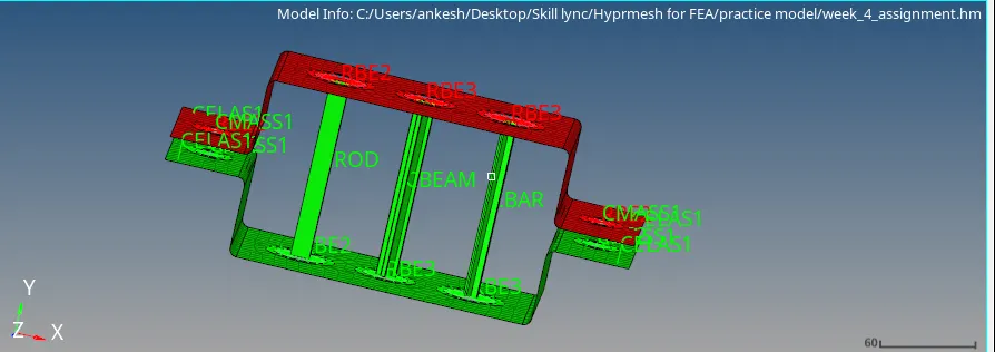
1d traditional representation
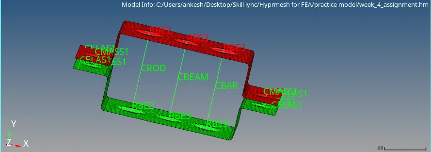
1d detailed element representation
Link: https://drive.google.com/file/d/1Xx2PqvoHRPapUkswDDXlX_uCYGScNKMG/view?usp=sharing
Conclusion:
1D element with given cross section and dof are successfully created on given component.