Week 4- Challenge
OBJECTIVE:
To Mesh the Given component with the Size of 5mm. Create 1D elements on the following component with given cross-section and DOF.
a.For Rod element:- Translational DOF should be Constrained with RBE2 link
Cross-Section: BOX- Dimension a= 12 mm
dimension b=10 mm
Thickness t= 0.75 mm
Beam element:- All DOF should be constrained with RBE3 link
Cross-Section: I Section- Dimension a= 8 mm
Dimension b= 10 mm
Dimension c= 8.5 mm
Thickness t1= 0.75 mm
Thickness t2= .6 mm
Thickness t3= .6 mm
Bar element:- Constrain only x and y DOFs With RBE3 link
Cross-section: X section- Dimension DIM1= 5 mm
Thickness DIM2= 1.2 mm
Dimension DIM3= 10 mm
Thickness DIM4= 1.2mm
d&e.Apply the mass of magnitude 10 with the RBE2 link.
f.Join the two components with Spring elements
PROCEDURE:
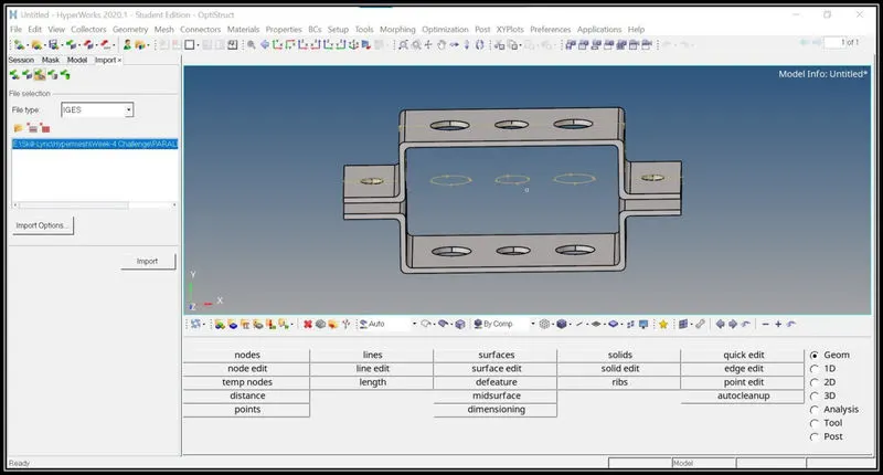
- The first step is to import the model using the import option in the standard menu tab.
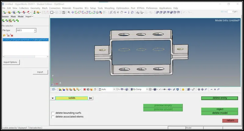
- Since we will be working on the 2d components, delete all the solids in the model.
- The next step is to create a mid surface.
- In the mid surface option, the auto mid surface option is selected and in the extraction option skin offset is selected in order to obtain the proper mid surface.
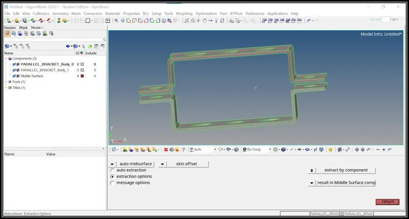
- Similarly, the mid surface is obtained for the lower bracket also.
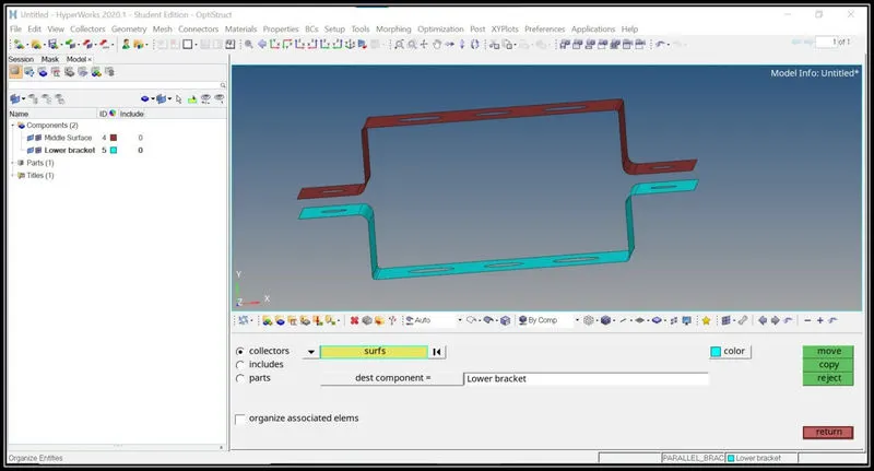
- Then a new component id is created and the lower mid surface part is moved to the newly created component id tab using organize option under the Tools tab.
- Change the colors for the Upper&Lower bracket in order to see that they are in different component id.
- Delete all other components in the list other than the two mid surfaces.
- The next step is to create a washer split around the holes in order to get a better flow of mesh along the path.
- The washer split is created using the washer split option under the quick edit tab.
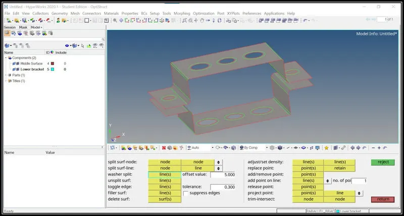
- The next step is to create a mesh.
- The mesh created using the auto mesh option in the 2-d menu tab.
- After entering the element size, click on the mesh option to generate a mesh.
- Then around the holes equalize the node number to improve the mesh.
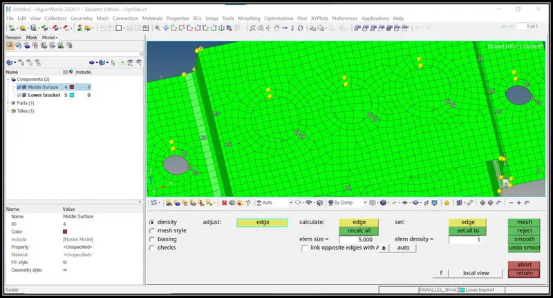
- The RBE2 elements are formed using the rigid option in the 1-d menu tab.
- As per given conditions they are constrained only in translation motion, so the rotational motion is allowed.
- Therefore uncheck the dof of 4,5,6 to allow the rotational motion.
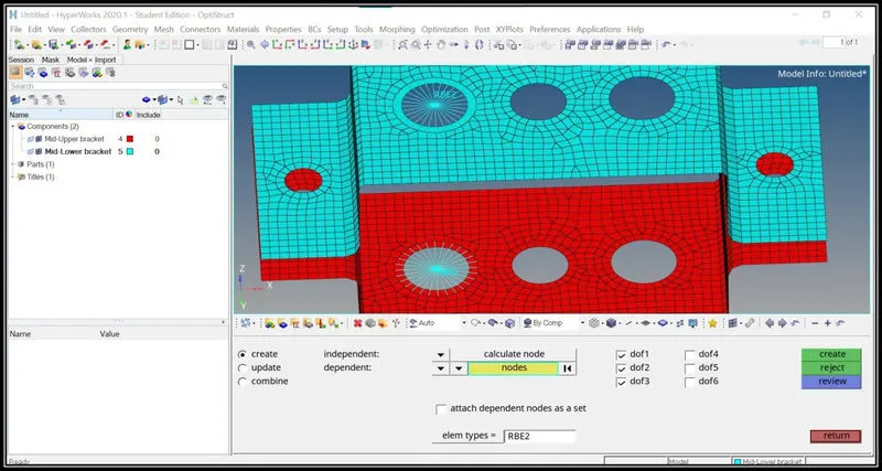
- Then for the beam RBE3 elements are to be formed.
- The RBE3 elements are formed using the RBE3 option in the 1-d tab.
- Based on the given condition, all dof must be constrained.
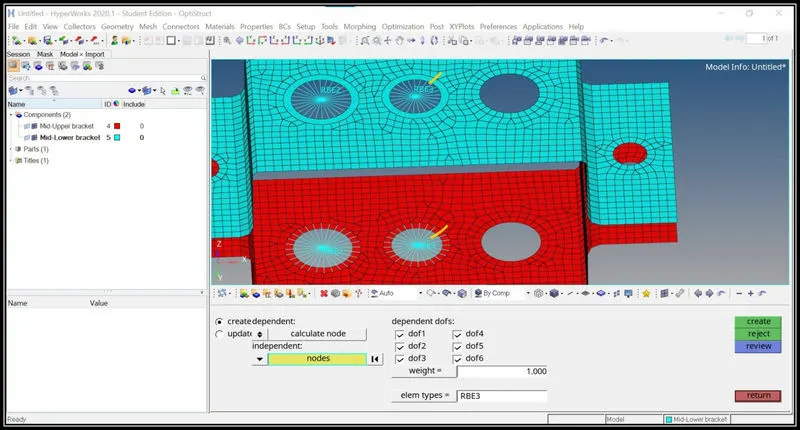
- Fo the bar element, RBE3 elements need to be used as per the given conditions.
- The RBE3 elements are created and the dof is constrained only in x and y.
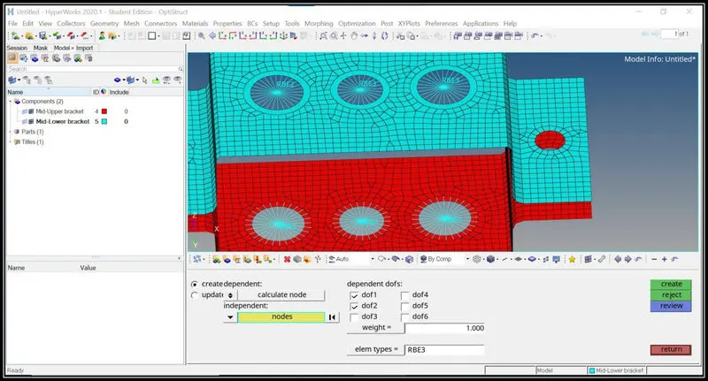
- Then spring element is created using the springs option in the 1-d menu tab.
- The element type is chosen as the CELAS1.
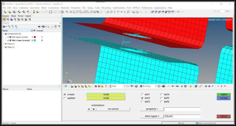
- Using the hyper beam option in the 1-d menu tab, the Rod, Beam, and the Bar dimensions are set as per the given conditions.
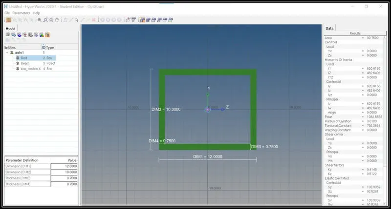
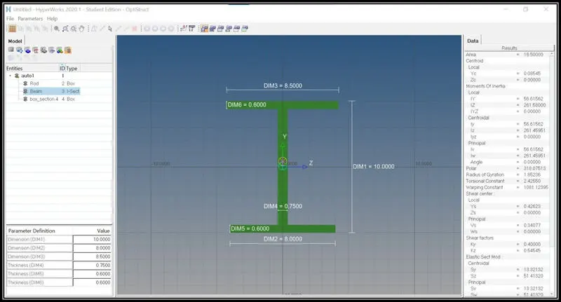
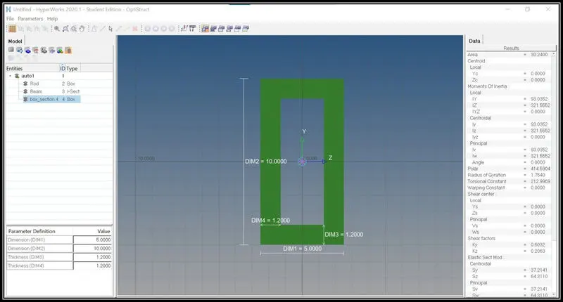
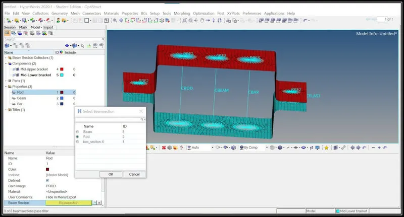
- A new property id is created for all the three elements and in that the card image and the beam selection are selected according to each section.
- For example: for the rod section the card image is chosen as Prod and the beam selection is chosen as beam(As per the name used in the hyper beam).
- Similarly for other two sections are created like this.
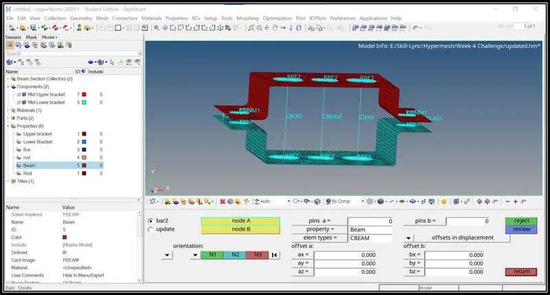
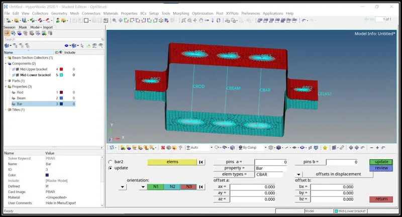
- Then for the side holes, RBE2 elements are created and mass is applied according to the given conditions.
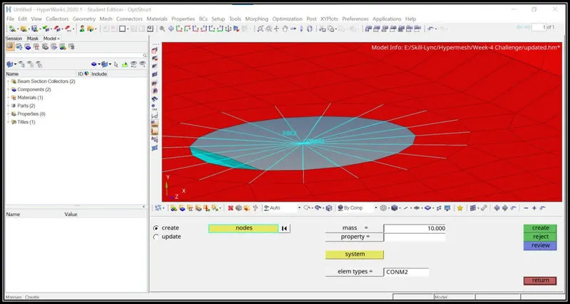
- Then the visualization is changed to 1-D Detailed Representation under the color menu tab.
- Then the all the Rod, Beam, and the Bar are visualized properly.
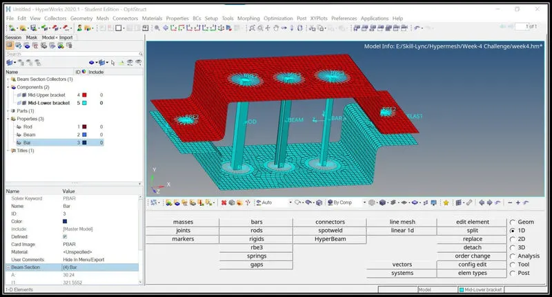
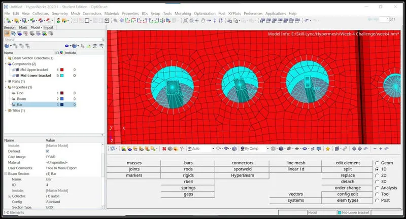
Conclusion:
- Understand how to create a Mid surface for the model and mesh according to the given conditions.
- Understand to create 1-d elements according to the given conditions.