Week 4- Challenge
AIM
To Mesh the Given component with the Size of 5mm. Create 1D elements on the following component with given cross-section and DOF.
OBJECTIVE
Mesh the component and create the 1D element for the following component:
Rod element with only translational DOF and RBE2 link with:
Cross section: BOX dimension a = 12mm, dimension b = 10mm, Thickness t = 0.75mm
Beam element with all DOF and RBE3 link with:
Cross ssection: I – Dimension A = 8mm, Dimenison B = 10mm, Dimension C = 8.5mm, Thickness t1 = 0.75mm, thickness t2 = 0.6mm, thickness t3 = 0.6mm
Bar element with x and y DOFS and RBE3 link with:
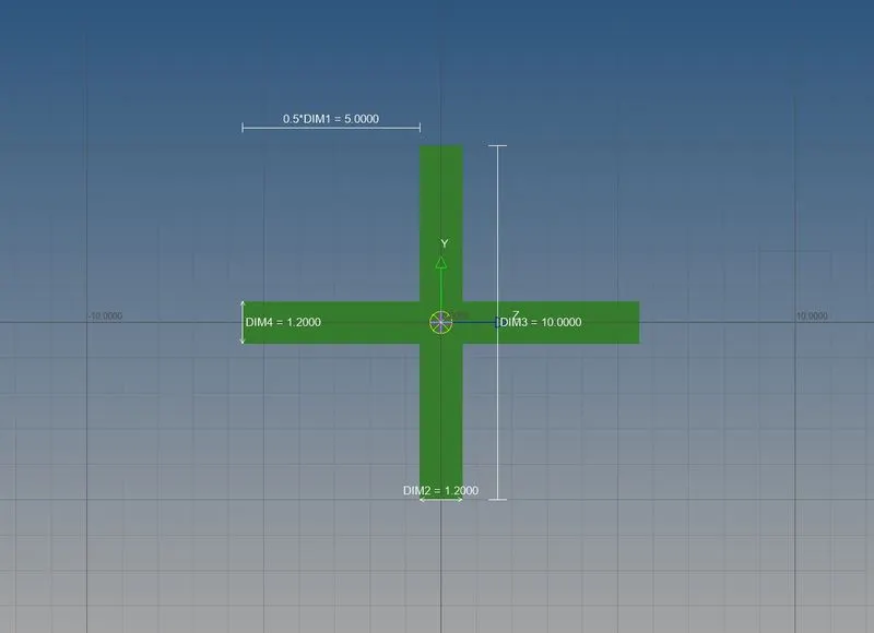
Cross section – Cross dimension Dim1 = 5mm, dimension Dim2 = 1.2mm, Dimension Dim3 = 10mm, Dimension Dim4 = 1.2mm
Apply the mass of magnitude 10 with rbe2 link
Join the two components with Spring elements
PROCEDURE
- Import the given IGES model file from import option.
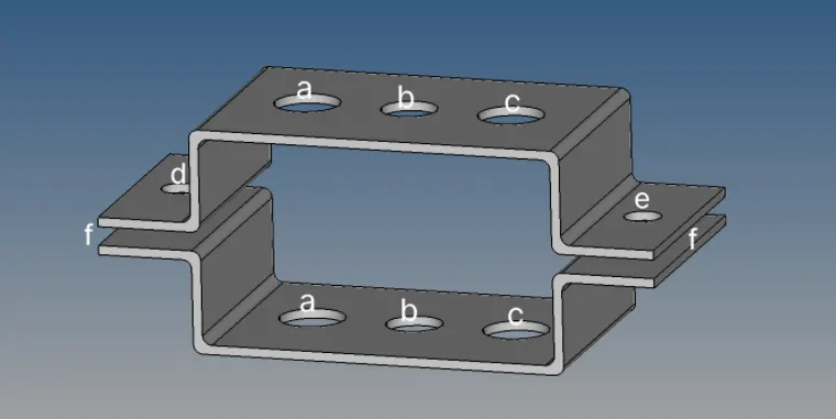
- After importing extract, the mid- surface from geometry tab -> mid surface portion for both the brackets separately.
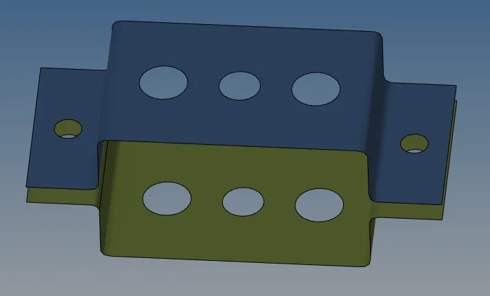
- Mention the component names for brackets an delete the solid part of bracket.
- Create washer split around trimmed areas
- Assign the property for this as given:
- Create the material property card and assign the material as steel to it
- Also assign thickness of 2.0mm for both the brackets
- Mesh the given brackets as mentioned:
- From 2D option on toolbar, select auto mesh and mention the element size as 10mm

- Then create 1D elements for the following:
- Various RBE2 and RBE3 links are created as mentioned in objective.
A) ROD ELEMENT RBE2
Select 1D option from toolbar
- Then select rigid option form there
- Uncheck the DOF 4 5 and 6
- Select node by path
- Select all the nodes and click create.
B) BEAM ELEMENT
- Select 1D option from toolbar
- Then select RBE3 from there
- Check all the DOF
- Select nodes by path
- Select all nodes and click create as mentioned above
C) BAR ELEMENT
- Select 1D option from tool bar
- Then select RBE3 from there
- Uncheck DOF 3 and DOF 6
- Select node by path as other two and select all nodes and click create as mentioned in above
Create elements from 1D
- Click on hyper beam
- From the generic section create hyper mesh and select Box
- We need to input values for the box as mentioned in the question
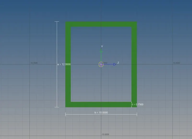
- Again, select hyper beam from toolbar
- Go to generic section
- Click on create and select hyper mesh
- Then select I section from there and input the values as given
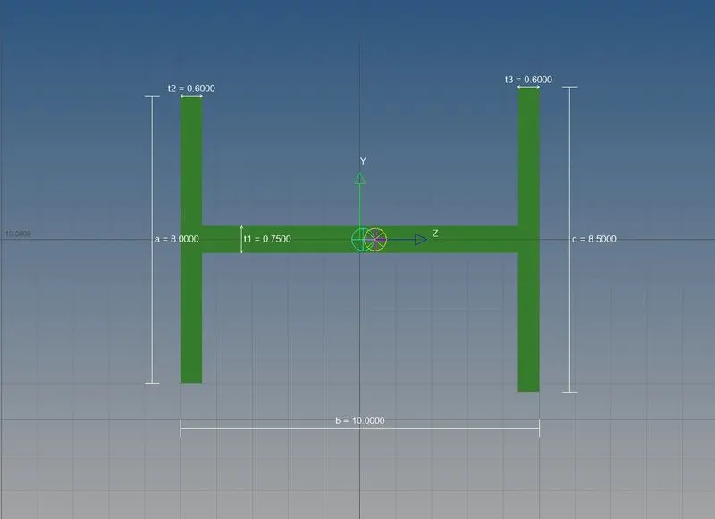
- For third time again go to hyper beam from toolbar
- Go to generic section
- Click on create and select Opti struct
- Click on cross and input the values as given.
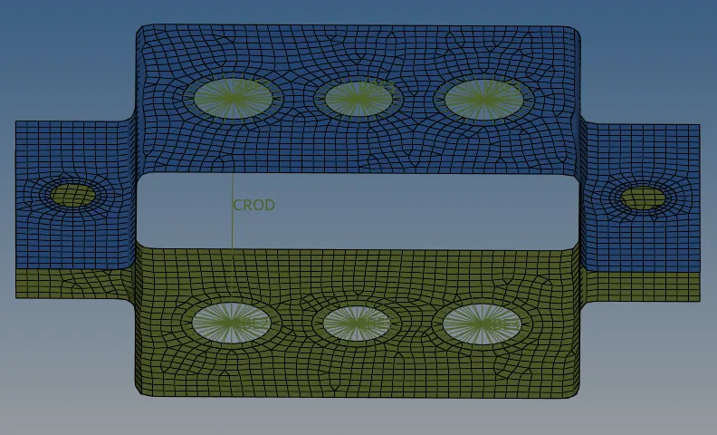
Select Model view option from Toolbar to create following components
To create rod
- Click on 1D option from toolbar
- Select nodes
- Create and update it as CROD
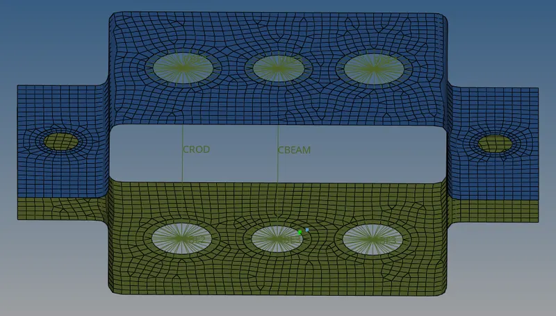
To create beam
- Click on bar in 1D from tool bar
- Select element type as CBEAM
- Select the nodes
- Select the cross-section and apply it
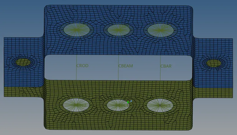
To create bar
- Click on bar in 1D option from toolbar
- Select nodes
- Select the cross-section and apply it as above mentioned in beam
Create properties for ROD, BEAM, AND BAR
- In rod properties change cards image as PROD and mention it in the section
- In beam property change the card image as PBEAM and mention it in the section.
- In bar property change the card image as PBAR and mention it in the section.
To update the properties of ROD
- Click on bar on 1D
- Then select element type and properties
- Click on update
To update the properties of beam
- Click on bar in 1D option from toolbar
- Select element type as CBEAM
- Then click on update
To update the property of bar
- Select again on bar in 1D option from tool bar
- Select the elements and property
- Click on update
To view the model after updated the properties:
- Click on 1D detailed element representation which is on the tool bar.
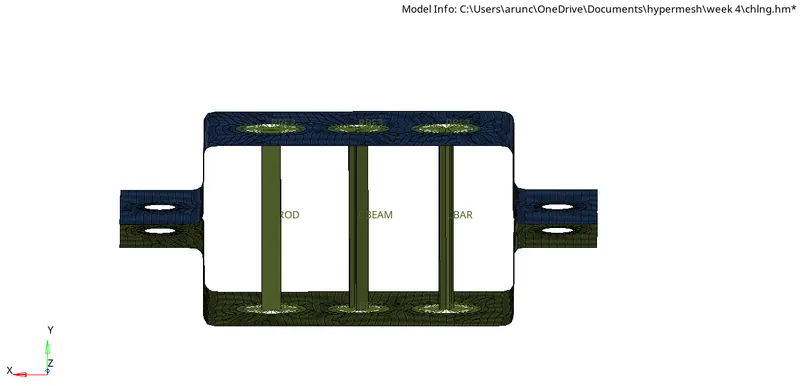
To apply the mass of magnitude 10 with RBE2 link in D & E
- Click on rigid in 1D
- Set as multiple nodes and calculate node
- Check all DOF as select the two sides nodes
- Click on create
Create new component and add property for Mass creation
- On property select material as steel
- In components update the property
To create the mass
- Click on 1D option from toolbar
- Click on masses from there
- Then assign the value as 10 in mass (as given in the question)
- Select the property as mass
- Select element types as CMASS
- Then at last click on create
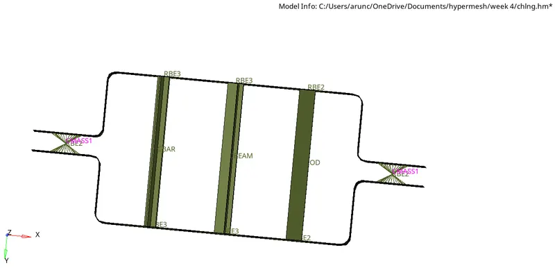
To create spring in F region
- Assign new component and property as Spring
- In Spring property
- Select material as steel
- In component select property as spring
- After that go to 1D option from tool bar
- Click on springs
- Select property
- Select as spring from there
- Select the element type as CELAS1
- Select the nodes where the spring is needed.
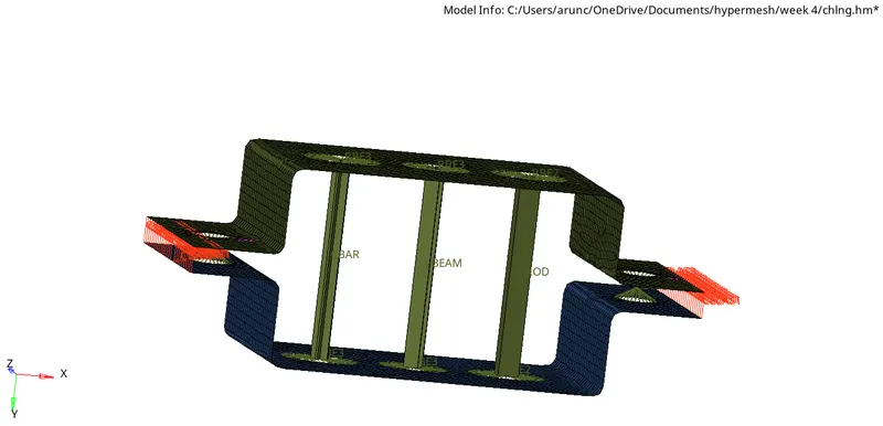
CONCLUSION
- Sucessfully learned to create the mid surface and auto meshing option.
- Learned to assign the various properties to the components.
- Learned the usages of 1D elements in hypermesh
- Also successfully created the 1D elements for given components as per the given dimensions and properties.