Challenge 1D connection in HyperMesh
Aim:
Creat 1D elements on the following component with given cross-section and DOF.
Objective:
1. The given component has to be checked for geometry errors, extract mid surface and mesh the mid surface.
2. Create properties for each part and create 1D elements connections of CBAR, CROD, CBEAM using Hyperbeam tool with RBE & RBE3 connections.
3.Assign thickness for shell elements and 1D elements connections.
Rod element:- with only translational DOF and RBE2 link
Cross-Section: BOX- Dimension a= 12 mm
dimension b=10 mm
Thickness t= 0.75 mm
b. Beam element:- with all DOF and RBE3 link
Cross-Section: I Section- Dimension a= 8 mm
Dimension b= 10 mm
Dimension c= 8.5 mm
Thickness t1= 0.75 mm
Thickness t2= .6 mm
Thickness t3= .6 mm
c. Bar element:- with only x and y DOFs With RBE3 link
Cross-section: CROSS section- Dimension DIM1= 5 mm
Thickness DIM2= 1.2 mm
Dimension DIM3= 10 mm
Thickness DIM4= 1.2mm
d. & e. apply the mass of magnitude 10 with RBE2 link
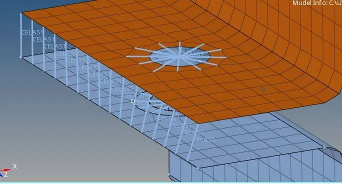
f. Join the two components with Spring elements
Introduction:
Procedure:
1. Open the model in Hypermesh before for geometry issues and fix them.
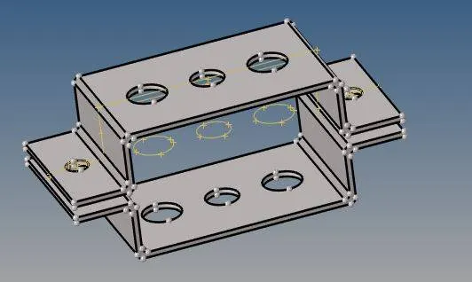
2. Used auto mid surface to extract from the parent body.
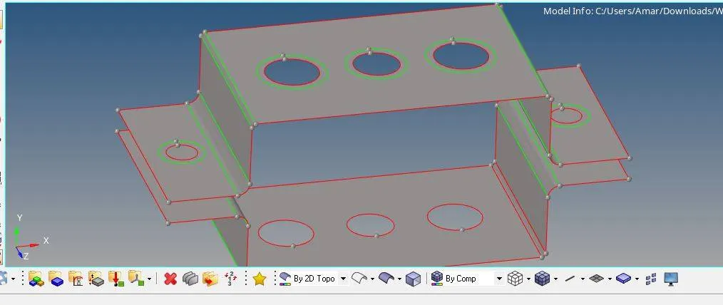
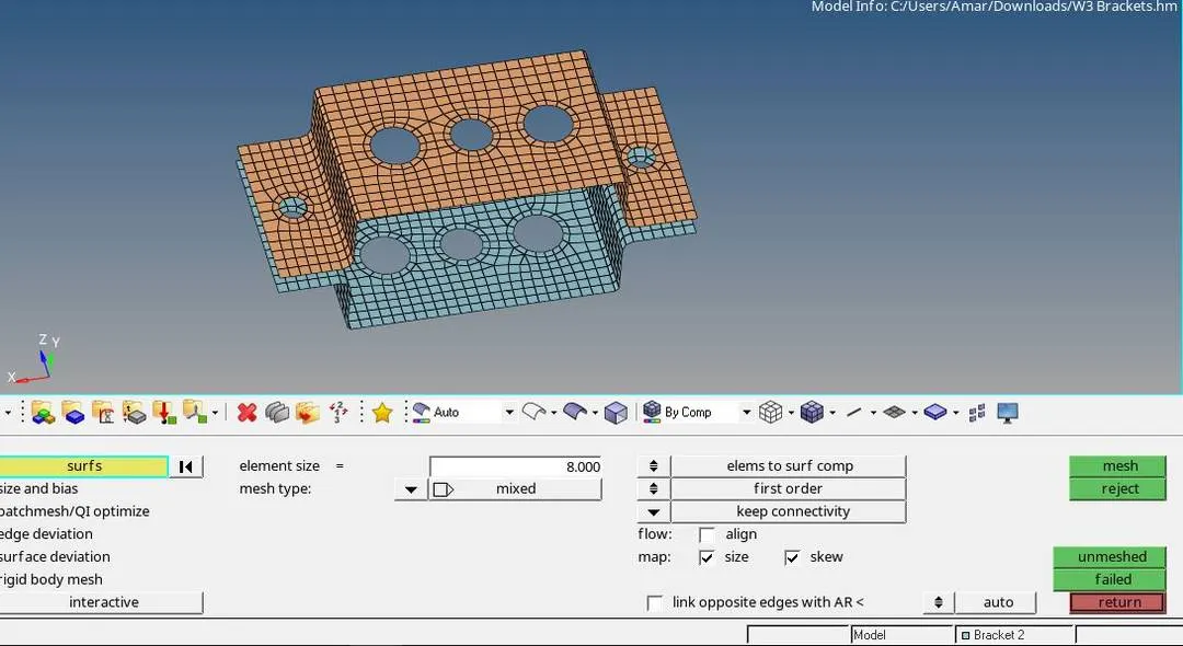
3. Now I have created a washer surface to get better mesh near the holes and used manual mesh to mesh surface by surface.
4. To create RBE2 link with only translational DOF
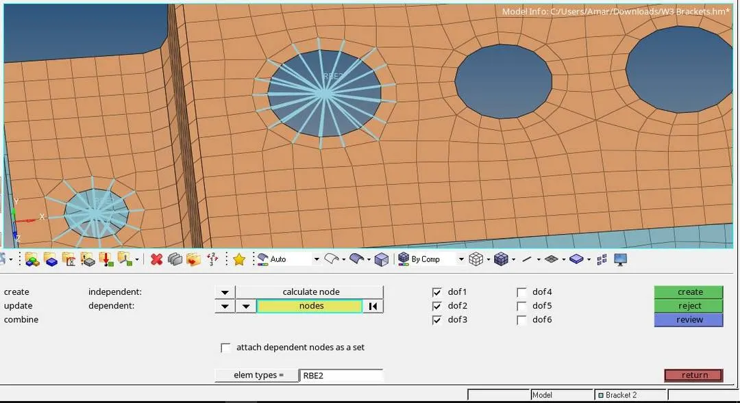
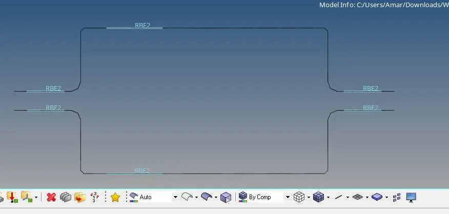
At the two ends applied the mass of magnitude 10 with RBE2 link
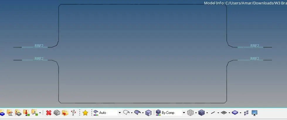
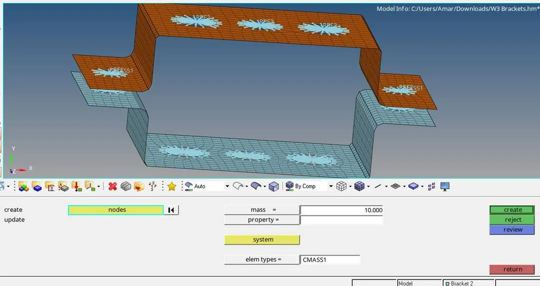
5. With all DOF and RBE3 link is created on two brackets parallelly.
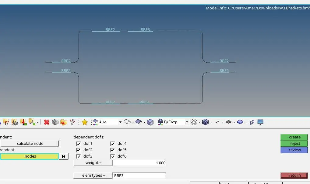
6. Create RBE3 link with only x and y DOFs.
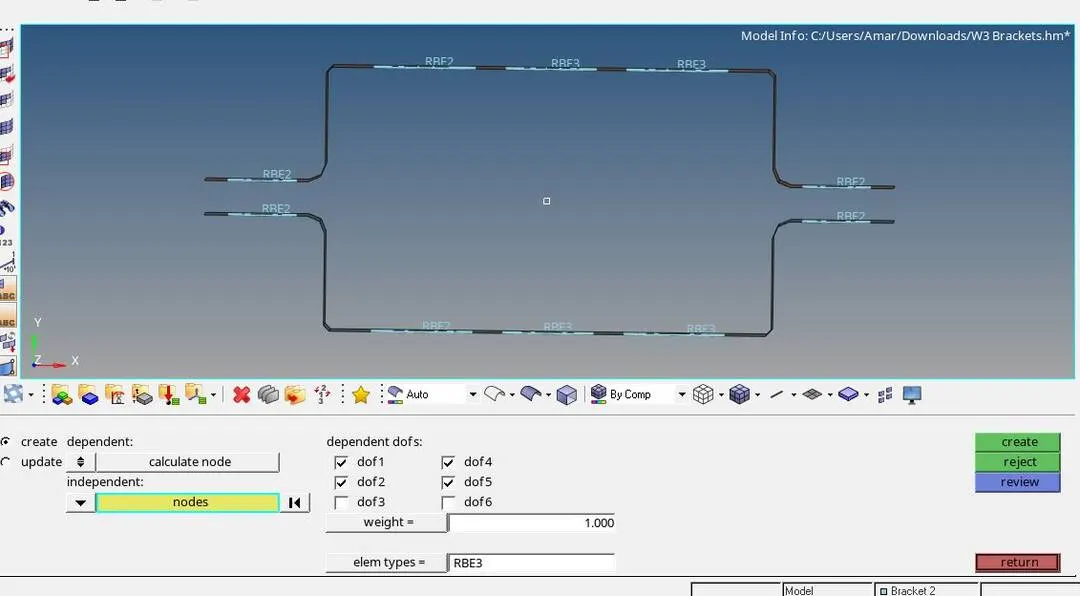
7.Now after creating rigid we have to create 1D Rod element with only translational DOF and RBE2 link.
Beam element with all DOF and RBE3 link, Bar element with only x and y DOFs With RBE3 link.
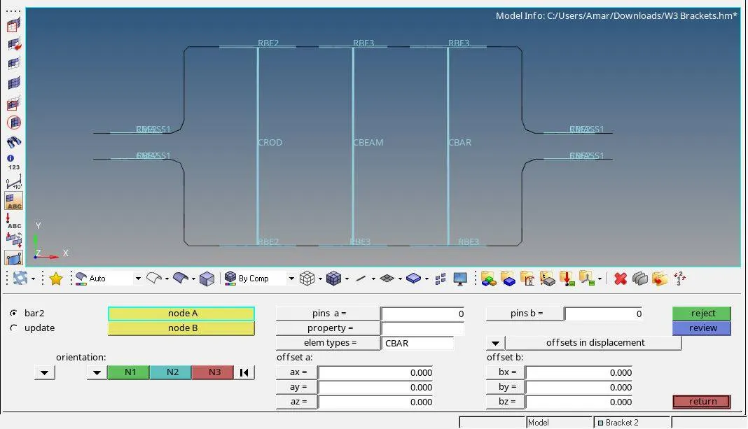
8. For representing the railroad, beam, bar we have to create it in the Hyperbeam tab with given parameters as shown in the image below.
Rod with Cross-Section: BOX Section,
Beam with Cross-Section: I Section,
Bar with Cross-section: CROSS section.
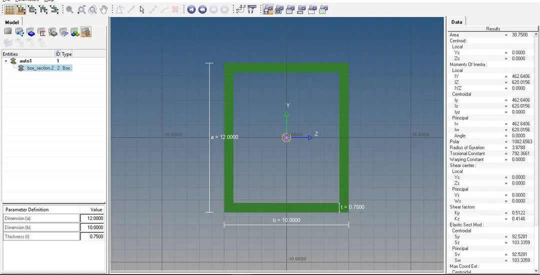
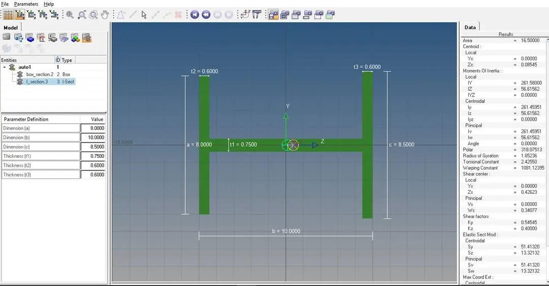
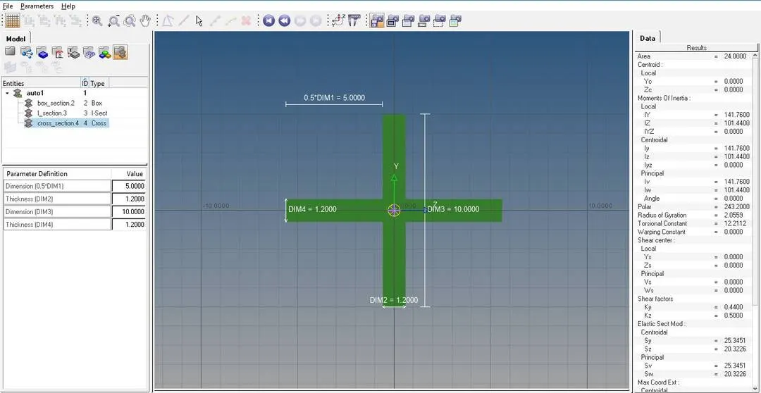
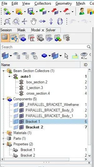
After creating these beams we can check the status of beams in the browser above components.
9.Once creating 1D beam elements we can see this in the beams showing local axis.
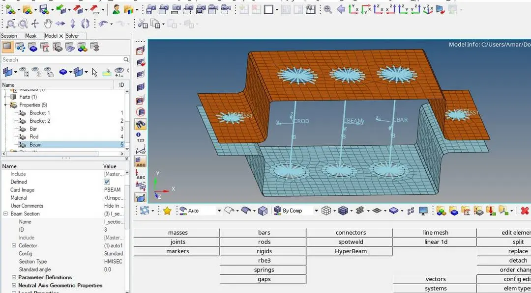
10. Now we have to assign the Hyperbeam property to the 1D beam property card. once it is assigned to that particular beams we can check by turning on the 1D detailed element representation.
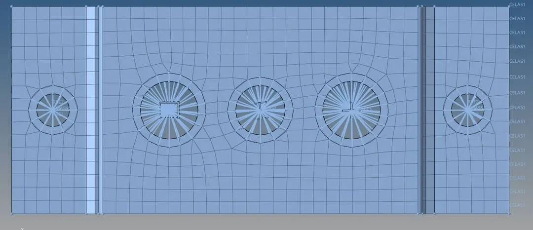
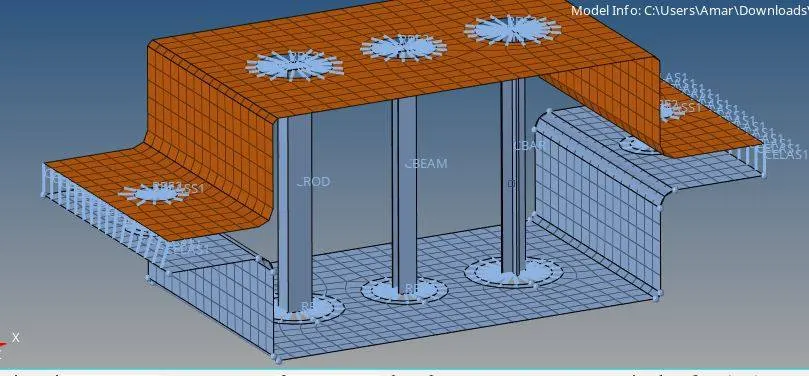
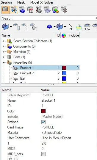
11. For connection two components together we have to create 1D Spring elements and sign thickness to components.
Result:
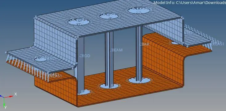
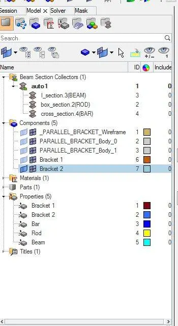
Conclusion:
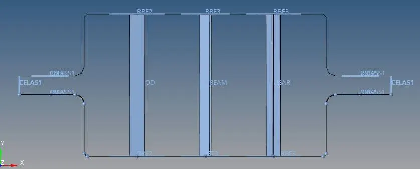
For the given model the thickness is assigned two components connected by 1D elements with Bar, Rod, Beam, Springs, Rigids, RBE3 links and mass is added on two corners of Rigids.