Week 4 Challenge
1.Define Tooling Direction?
Tooling Direction is basically that the mold pulls apart. The mold is build in two seprate pices.one is core side another one cavity side.Core pulls apart from the cavity that is dyeline or tooling direction.
2.Create tooling direction for Class A with 10 deg draft ( draft in command should be 10 deg) and show the draft analysis?
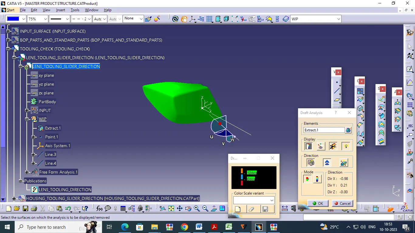
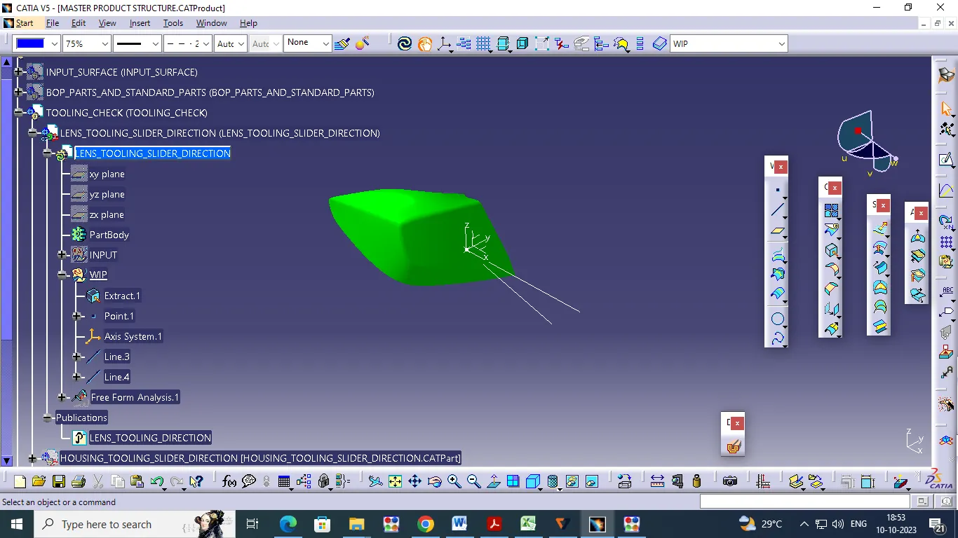
- Create input class-A surface in automotive lighting then we have been create on tooling direction with 10 def draft angle .how could we do this? first create point and axis the axis direction is ZY .And go to pick line option create line in direction ZY plane .
- Select the draft Analysis command pick the compass on tolling line and fix then go to pick on the class-A Surface the hole surface is didn't change the color green.because green color is represent in 10 deg draft angle .0 to 10 deg is represent in blue color,below 0 deg is represent in red color.
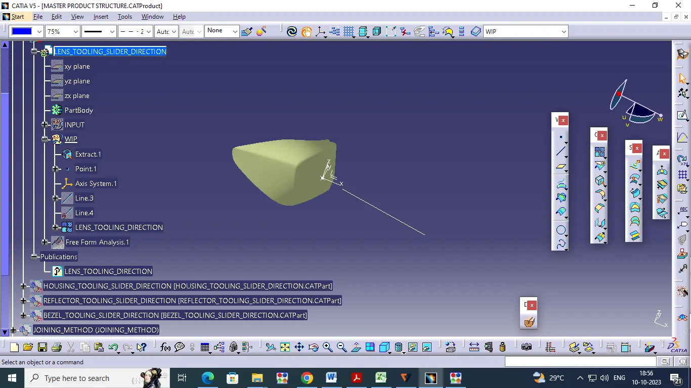
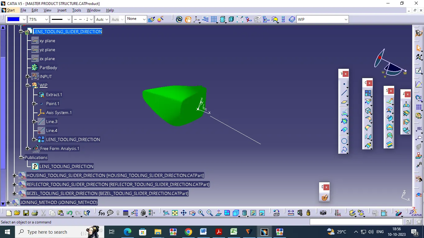
- So want to change in tooling line direction by using line option select (Angle and curve) and change direction in -12 deg then go draft analysis and fix the compass and check the draft the whole surface is green color.
TOOLING DIECTION FOR CLASS-A SURFACE WITH 10 DEG DRAFT ANGLE:
.
3.Write the definition of the Parting line?
The mold is made by one or more part like you have core side and you have cavity side .the core and cavity part are merging area or line is partning line .whenever insert the molten material go to the partning line gape and will exit little bit of molten material.
4.Create B surface of the given lens in surface modeling (not in part), with a 4 mm thickness?
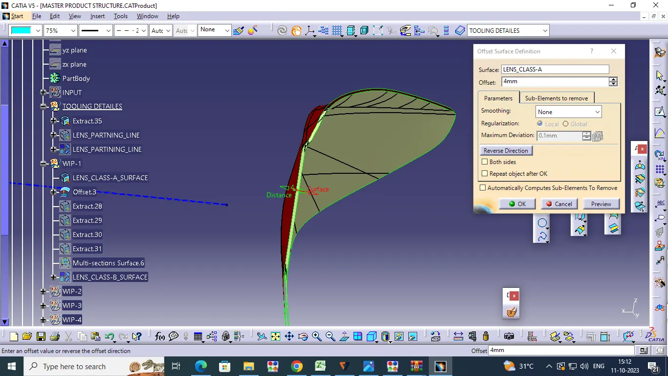
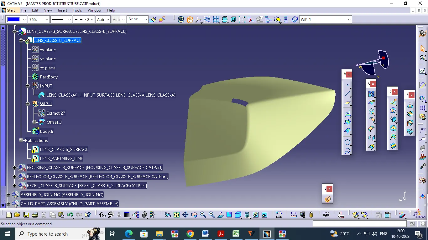
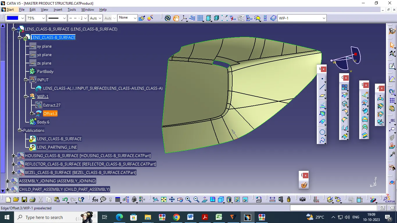
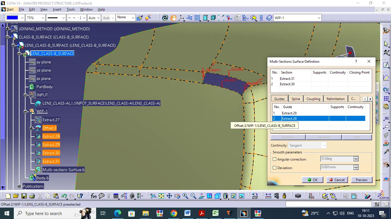
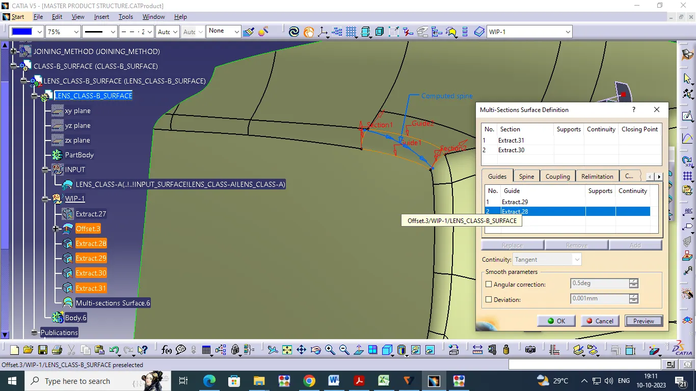
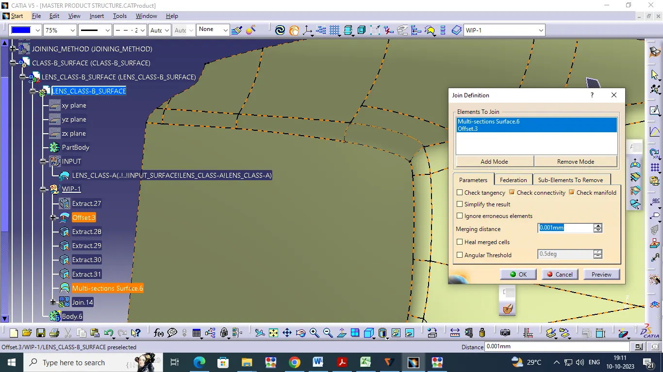
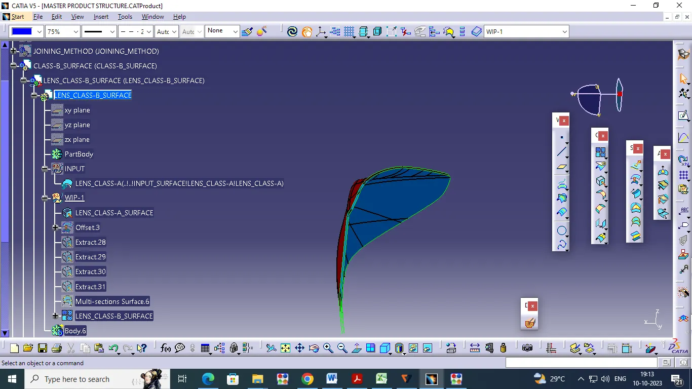
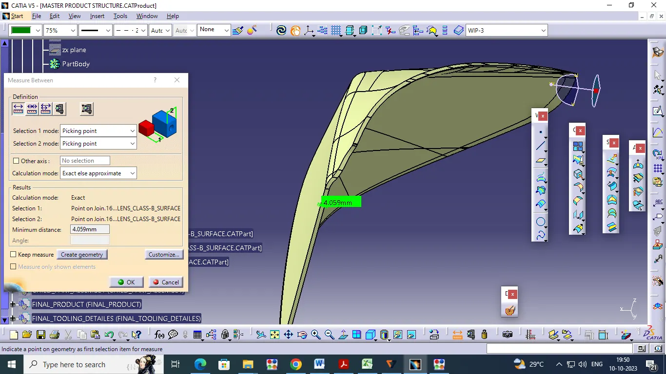
Create CLASS-A surface after make publication and copy the publication to past special(result in link) in the B- SURFACE product.That geometrical cody name is INPUT. Then create the geometrical body (WIP-1) and extrude in class -A Surface and offset the Class- B Surface in 4mm Thickness gap.some patches are create in B - Surface .beacuse the B-surface is distance between in 4mm gap from Class - A Surface .so rectify the patches in CLASS-B Surface by using multi section creation command and rectify the patches and use join command go to join the patch and surface.
CLASS B SURFACE CREATION:
5.Create a Parting Line for thickened lens and create a report for how you approached the parting Line and did a draft analysis?
- Create input class-A surface in automotive lighting then we have been create on tooling direction with 10 def draft angle .how could we do this? first create point and axis the axis direction is ZY .And go to pick line option create line in direction ZY plane .
- Select the draft Analysis command pick the compass on tolling line and fix then go to pick on the class-A Surface the hole surface is didn't change the color green.because green color is represent in 10 deg draft angle .0 to 10 deg is represent in blue color,below 0 deg is represent in red color.
- So want to change in tooling line direction by using line option select (Angle and curve) and change direction in -12 deg then go draft analysis and fix the compass and check the draft the whole surface is green color.
- Create CLASS-A surface after make publication and copy the publication to past special(result in link) in the B- SURFACE product.That geometrical cody name is INPUT. Then create the geometrical body (WIP-1) and extrude the boundary in class -A Surface and offset the Class- B Surface in 4mm Thickness gap.some patches are create in B - Surface .
- Beacuse the B-surface is distance between in 4mm gap from Class - A Surface .so rectify the patches in CLASS-B Surface by using multi section creation command and rectify the patches and use join command go to join the patch and surface.
- After create the B-SURFACE next we have open new geometriacl body thet name is WIP-2 .now extrude the class -A Surface and create the draft by using Swep command in 3 deg direction in inside .then expraplote the whole boundary in CLASS-B Surface.next trim the class-A & class-B.Then C- Surface will be created.And Join the whole Surfaces like : CLASS-A,CLASS-B & CLASS-C by using join command.
- Now create the body create the closed surface or thickend surface by using closed surface command.The BODY Name LENS CLASS-B.And create the another one Body .The LENS_CLASS-B is Add on the new Body.
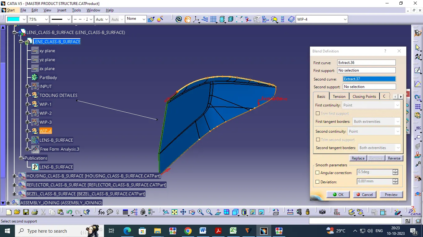
- Another one way is here in create in close suraface .that is create the extrude the boundary of class-A & class-B then using blend option to connect the class-A and class-B.and create another one extrude boundary in vertical side of surafces in class-A and create in draft angle by using Swep command in 3 deg inside direction.
- Then trim the class - B ,Swep and blend by using split or trim command and after trim the class c surface join the class B & class A by using join command.
- Now create the another one body create the closed surface or thickend surface by using closed surface command.The BODY Name LENS CLASS-B.And now that body LENS CLASS-B is replace that Previous body in LENS_CLASS-B .
- complete the clased surface the we have been analysis the draft angle in 10 deg draft.copy publiction the tooling direction line and create the another one geometrical body that name is ( TOOLING DETAIL ) and use past special click in (result in link) option.
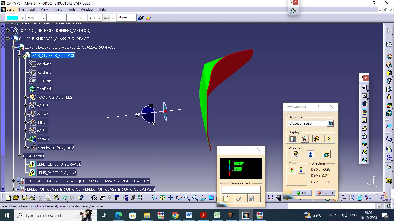
- Select the draft Analysis command pick the compass on tolling line and fix, then go to pick on the closed surface the hole surface is change the color green.because green color is represent in 10 deg draft angle .0 to 10 deg is represent in blue color,below 0 deg is represent in red color.
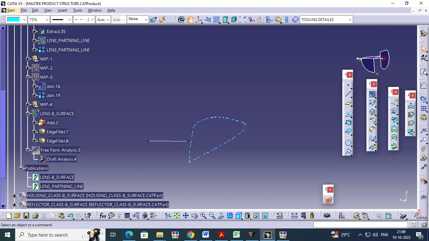
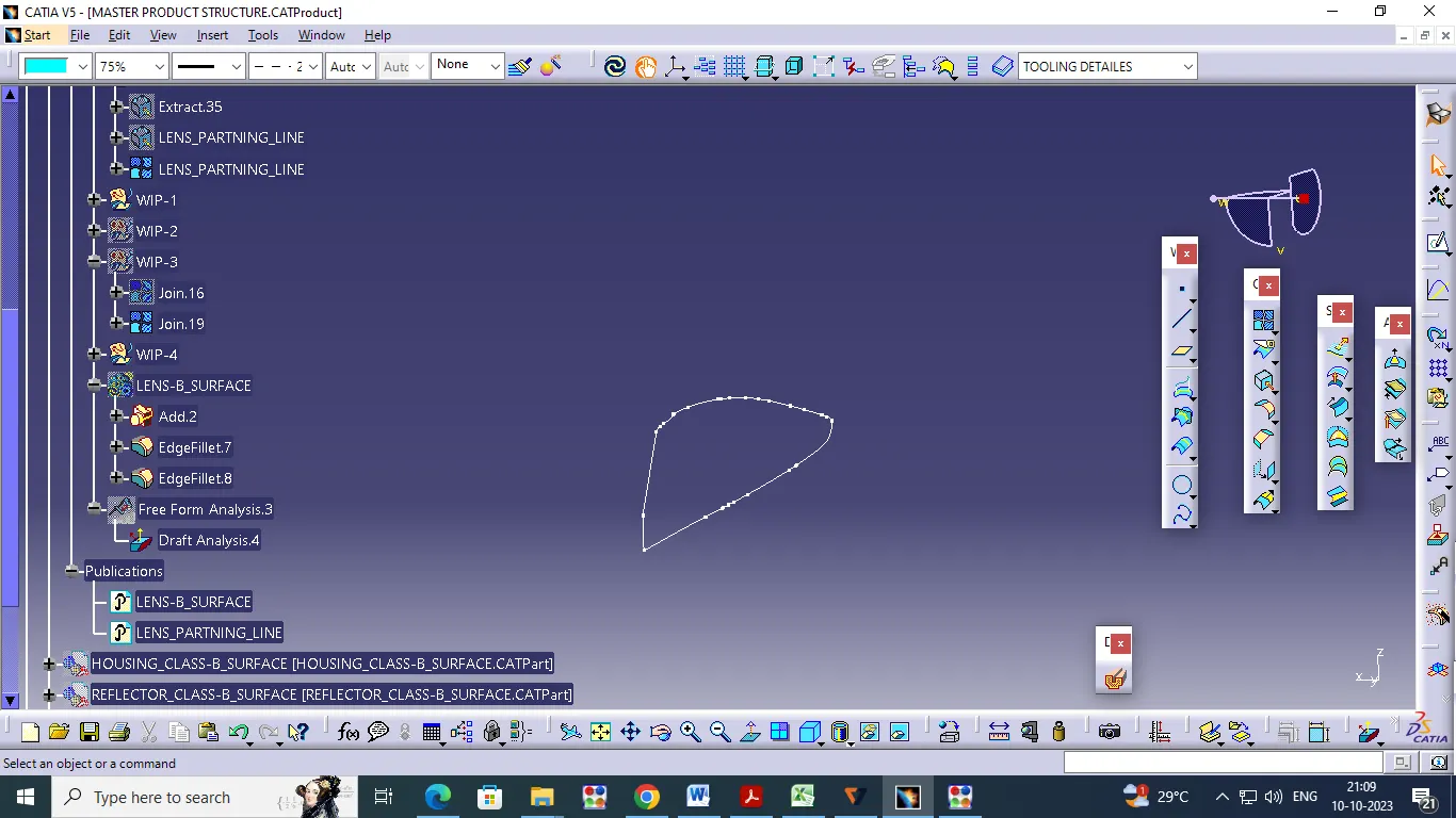
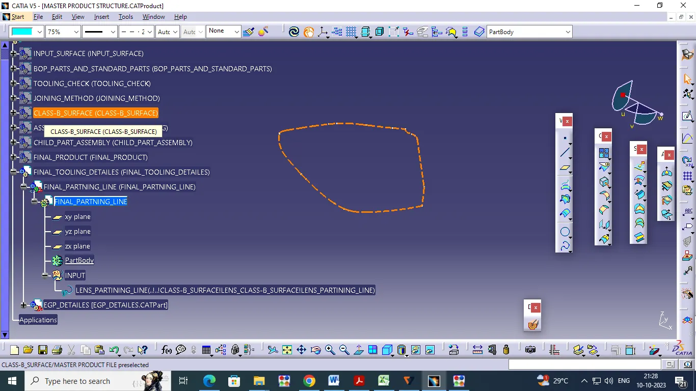
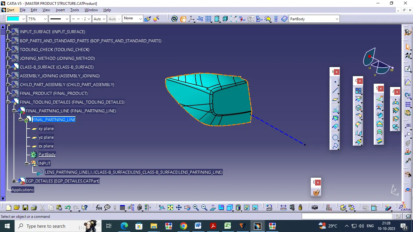
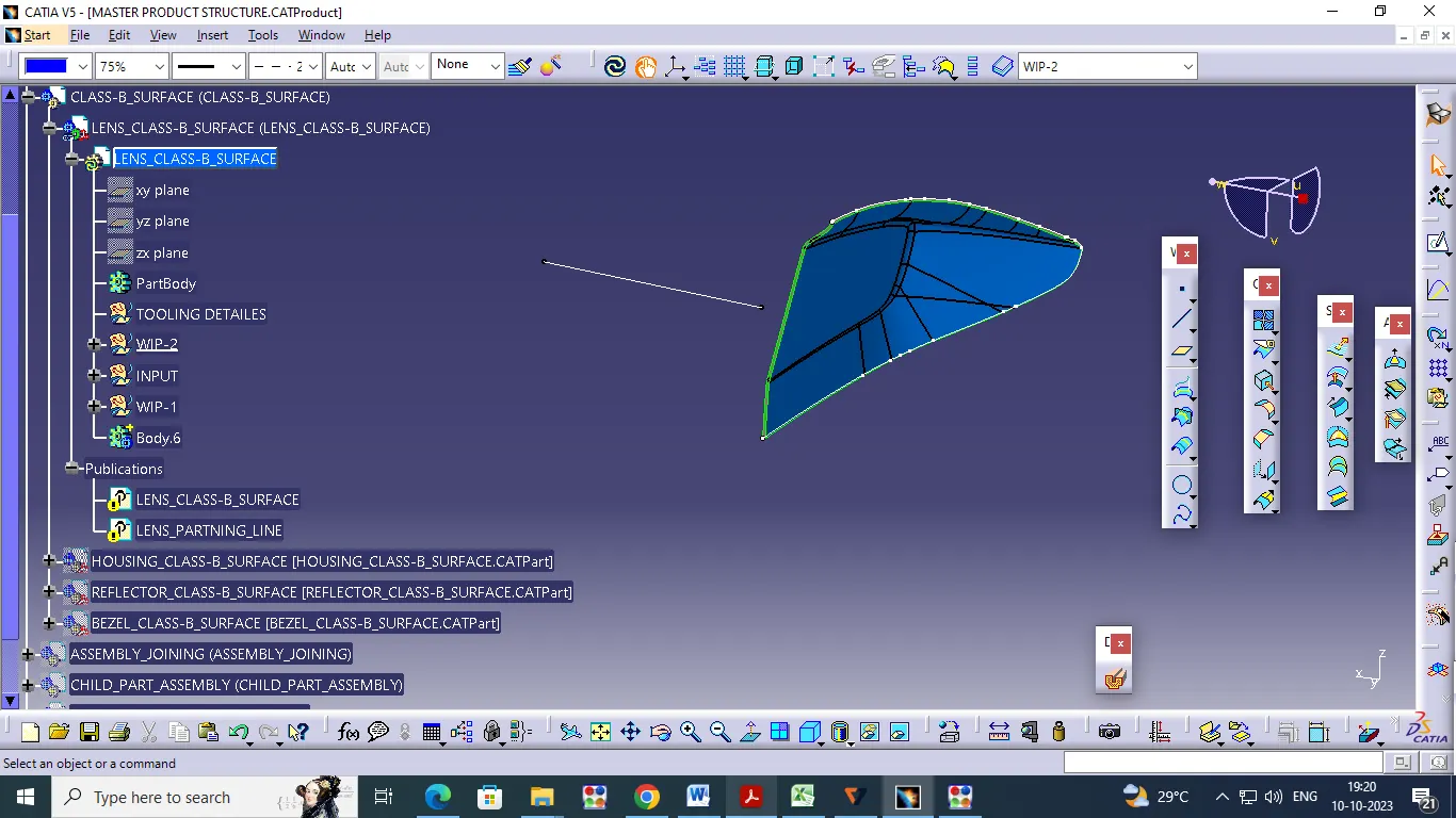
- After Draft analysis is we have extrude in boundary of CLASS-A surface side in closed surface . that boundary in PARTNING LINE.
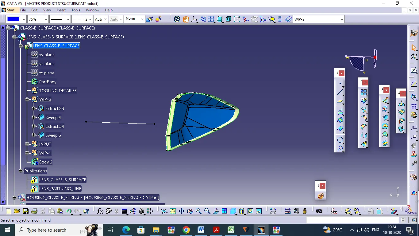
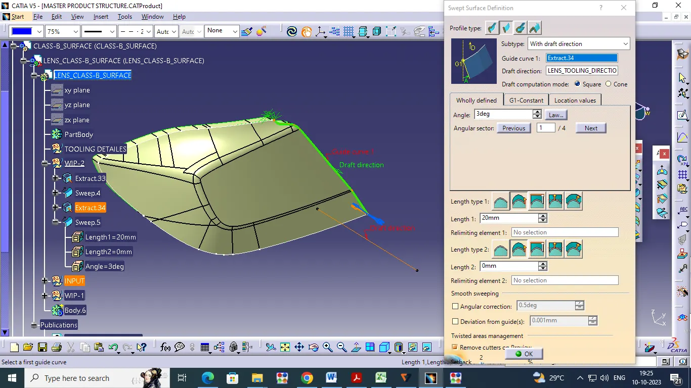
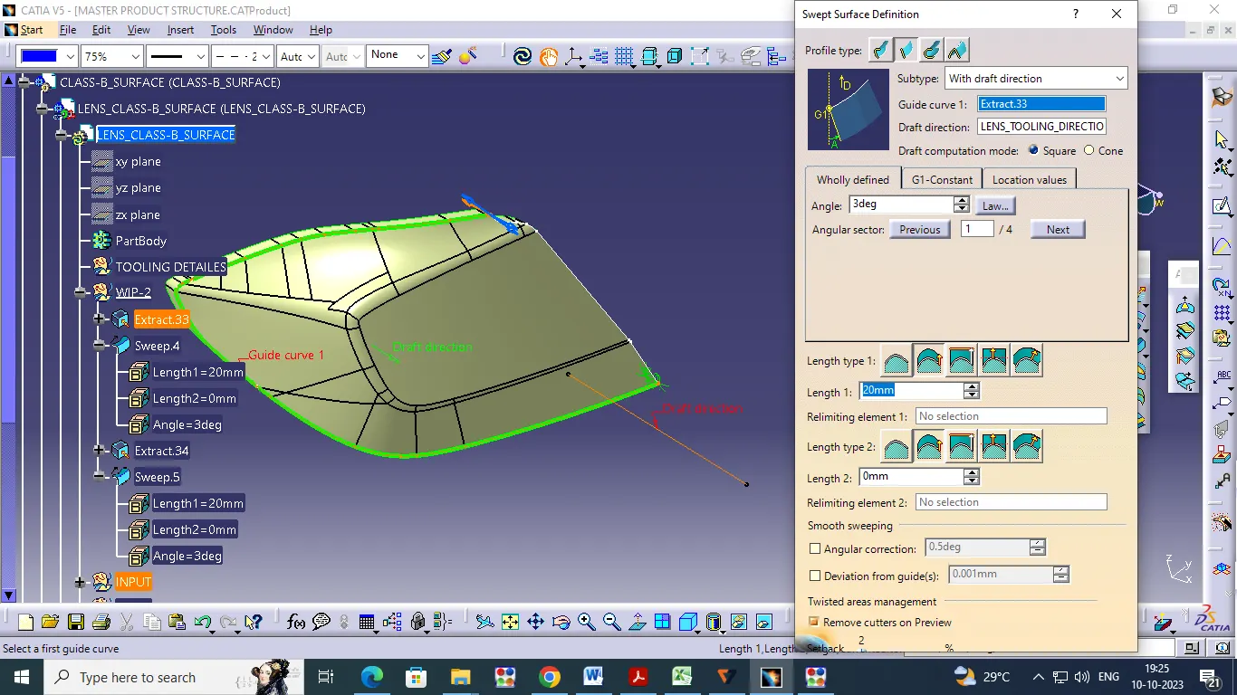
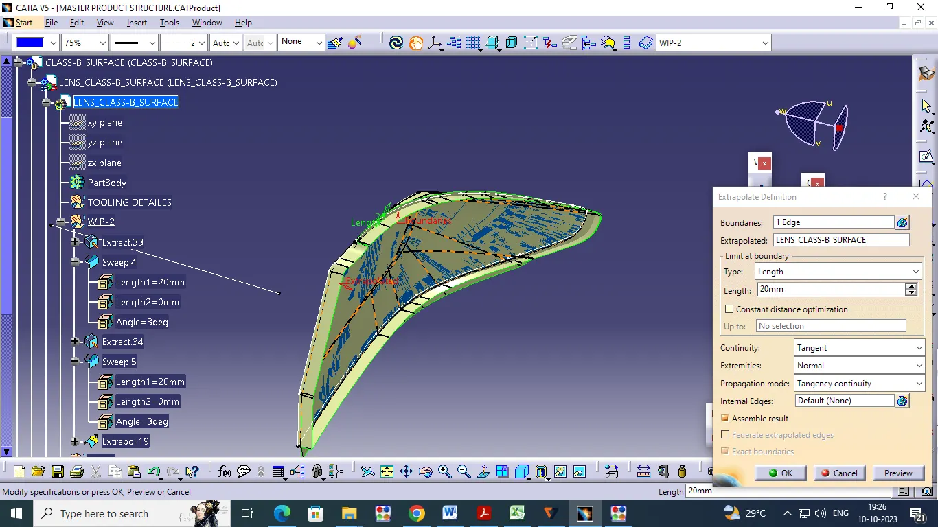
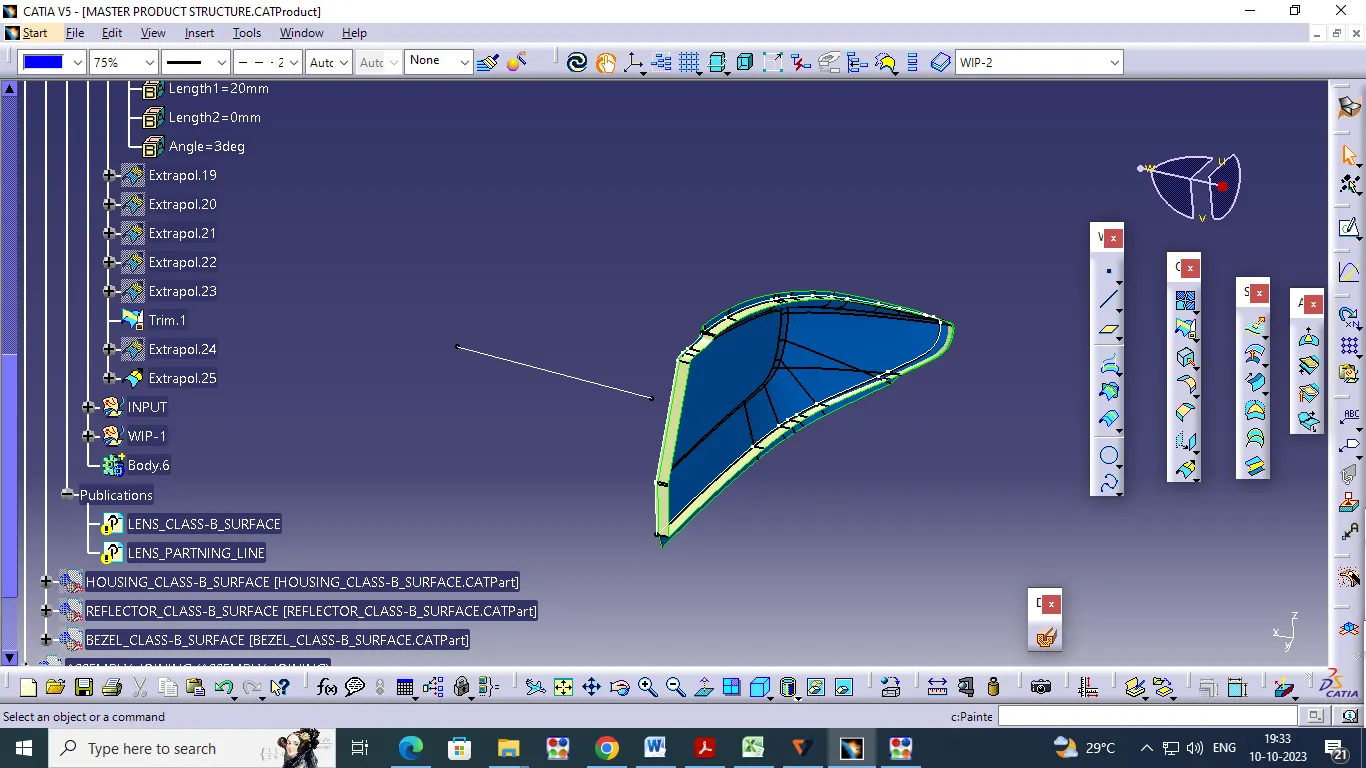
CLASS-C SURFACE:
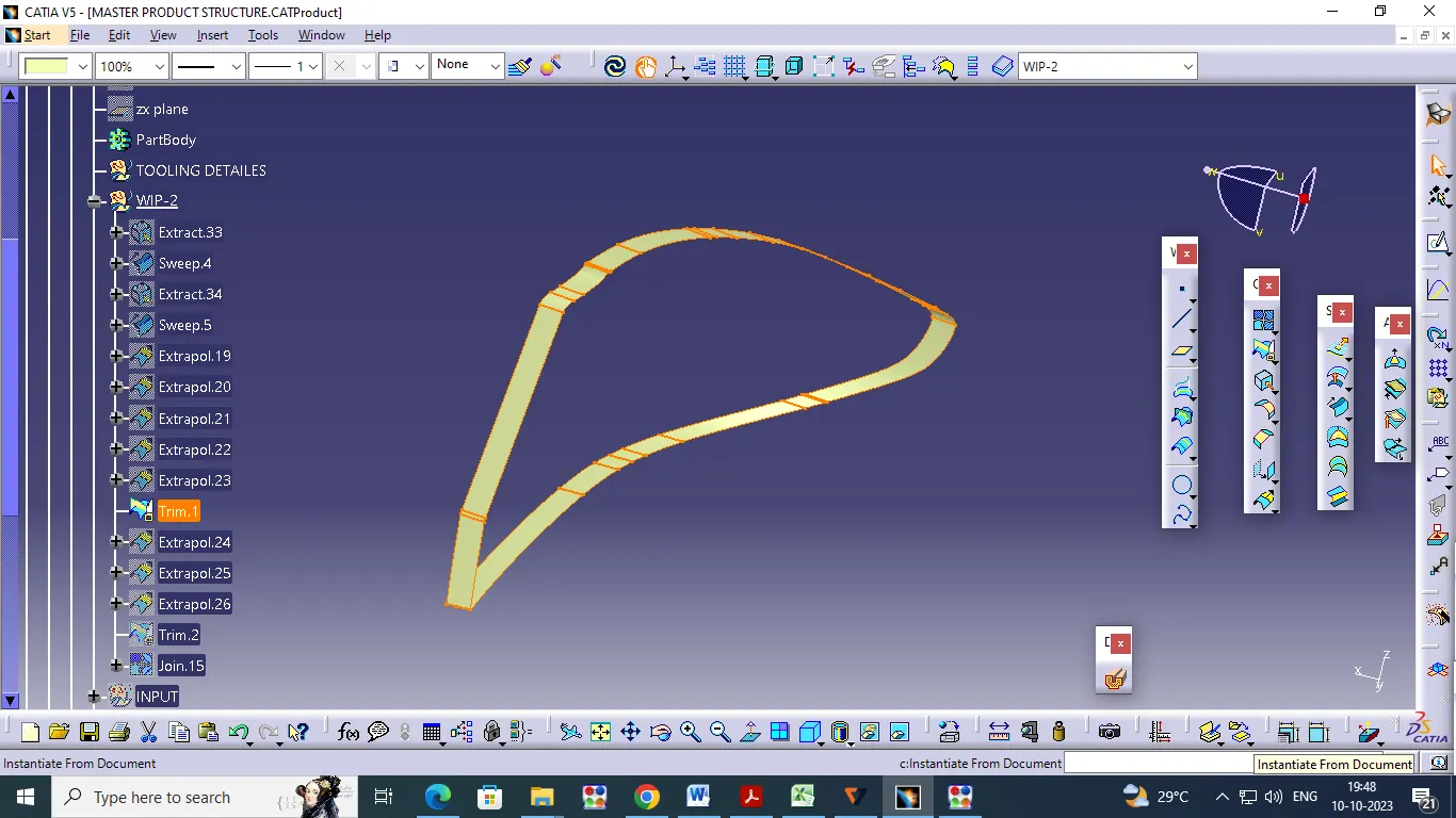
4MM GAP:
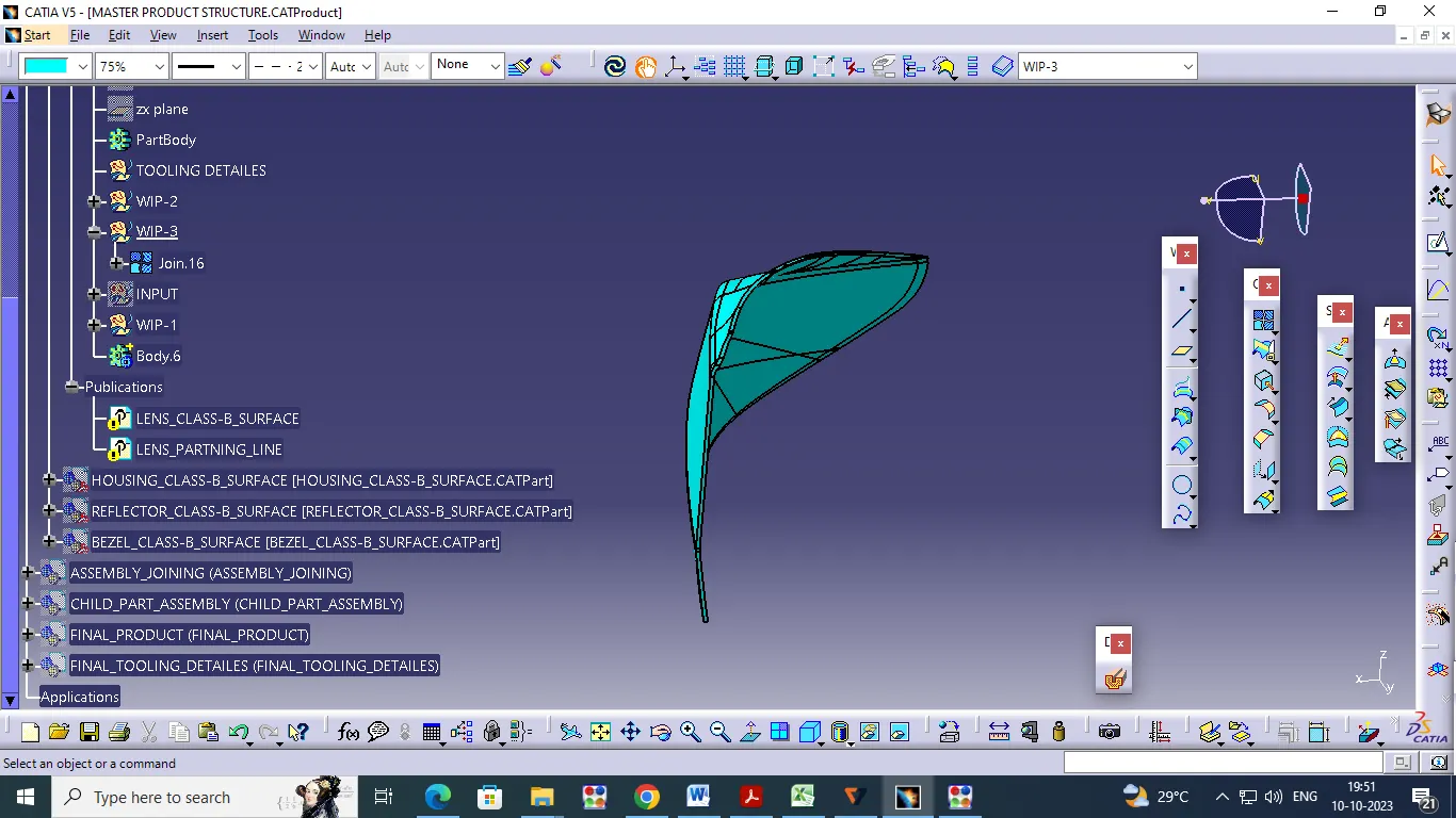
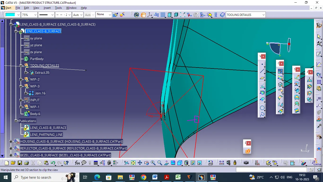
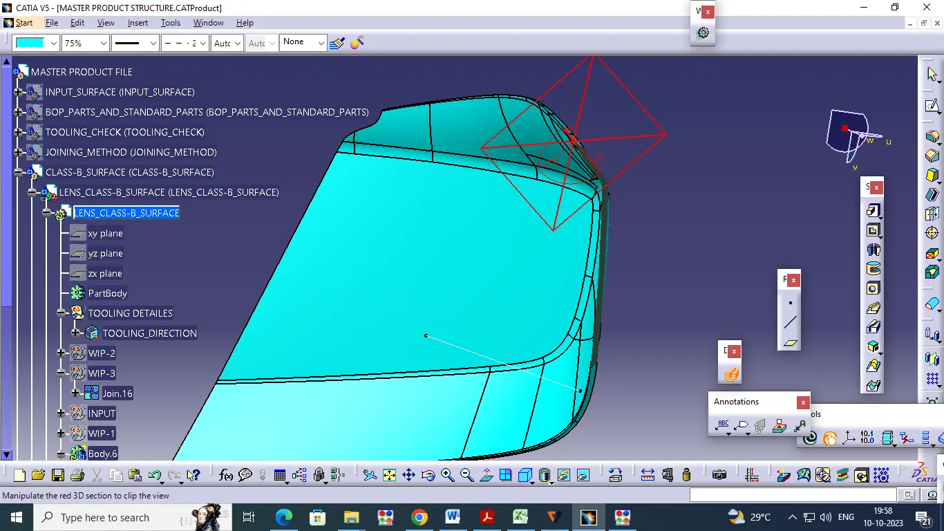
10 DEG DRAFT ANGE IN CLOSED SURFACE:
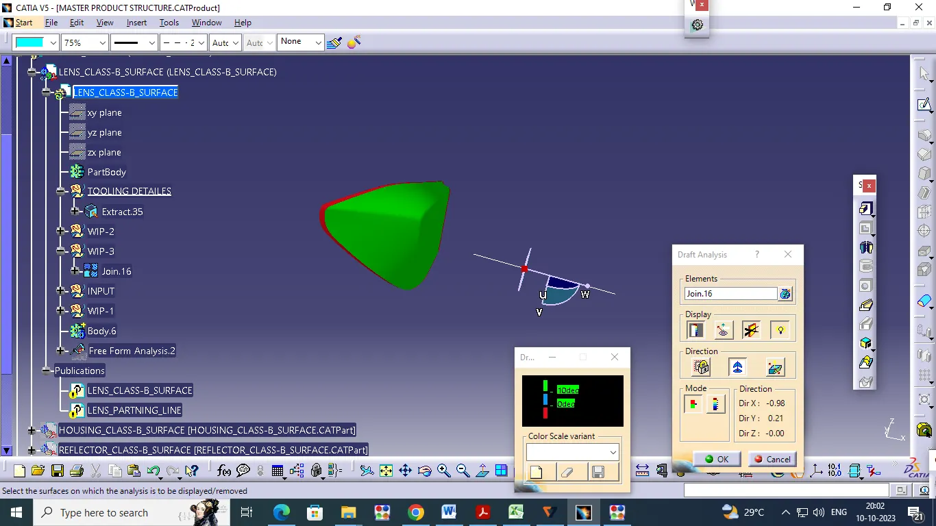
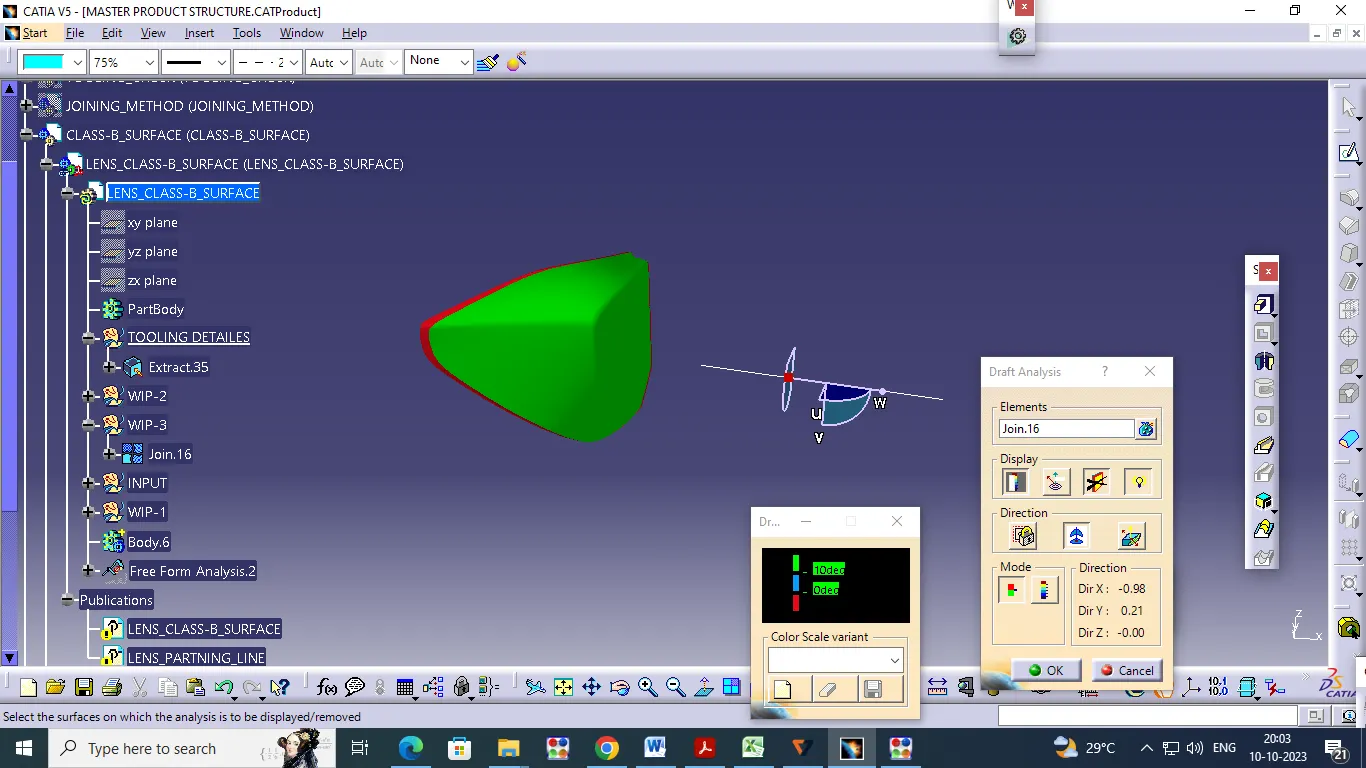
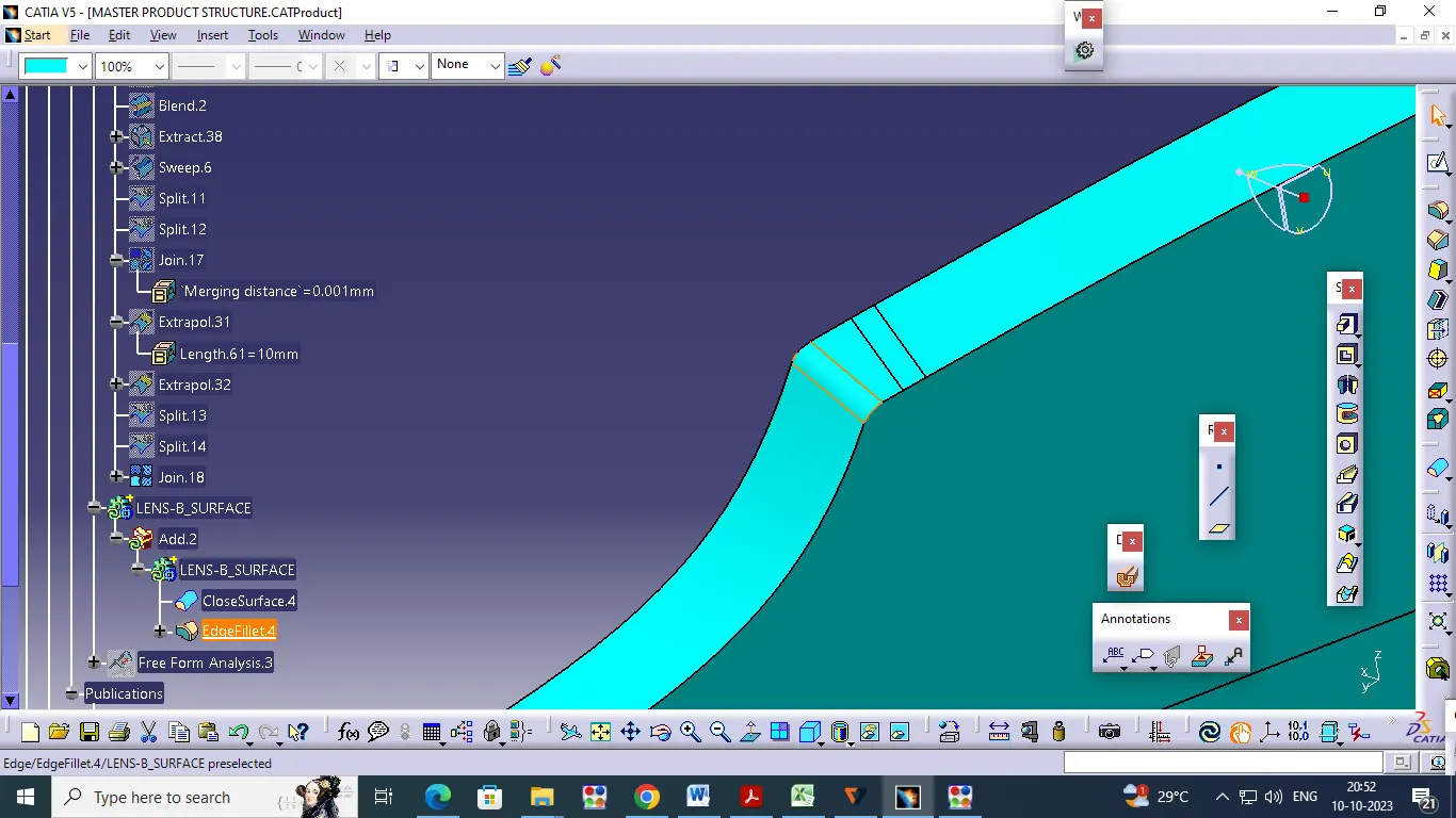
EDGE FILLET - 1 MM:
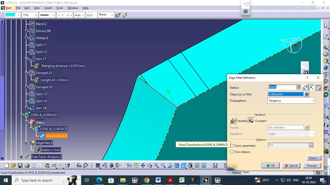
EDGE FILLET - 0.5 MM :
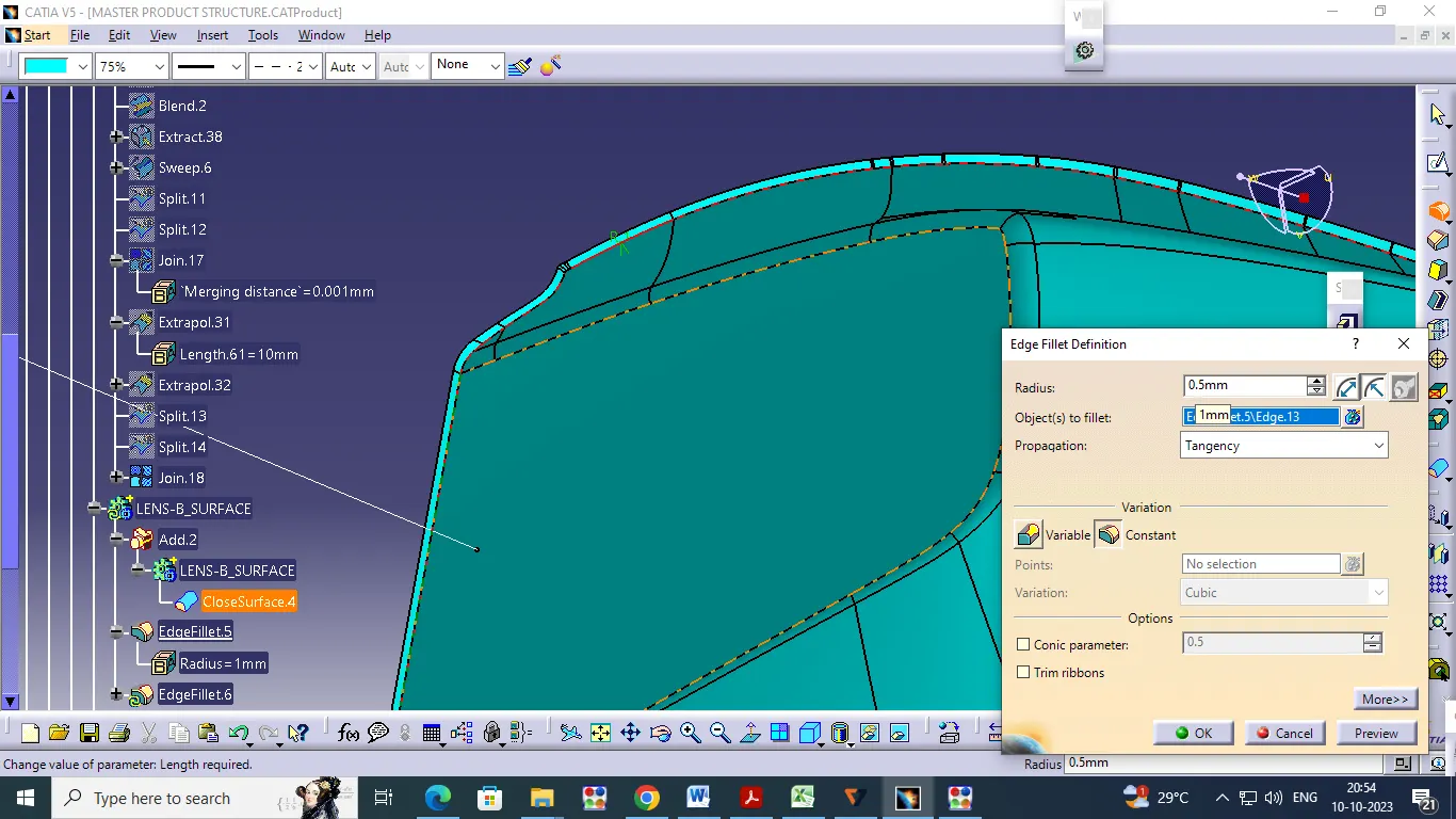
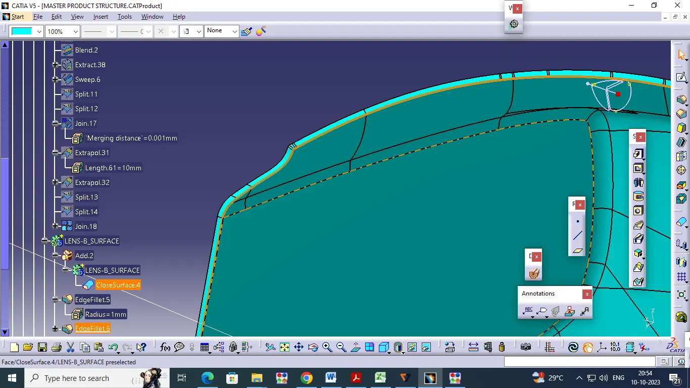
DRAFT ANGEL IN CLOSED SURFACE : LENS_B-SURFACE:
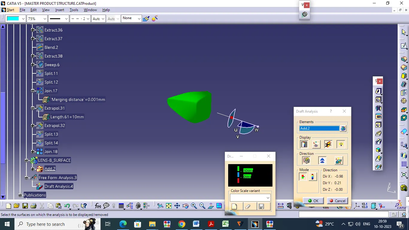
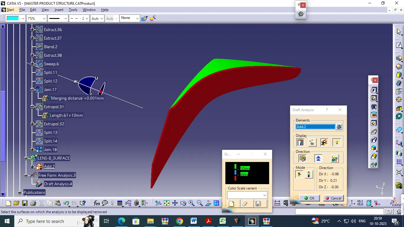
PARTNING LINE: