Week 4- Challenge
Creation of 1D Elements and Assigning Cross-section and Property to it
- when to use 1D elements
|
One of the dimensions is very large in comparison to the other two. |
||
|
Element shape: Line |
||
|
As, 1D element has only length, Area of cross section is required to capture the CAD geometry |
||
|
Element Type: |
||
|
Practical Applications: |
Aim
- To create 1D elements for the given component and assign cross-section and property to them
- Solid representation of 1D elements
Procedure
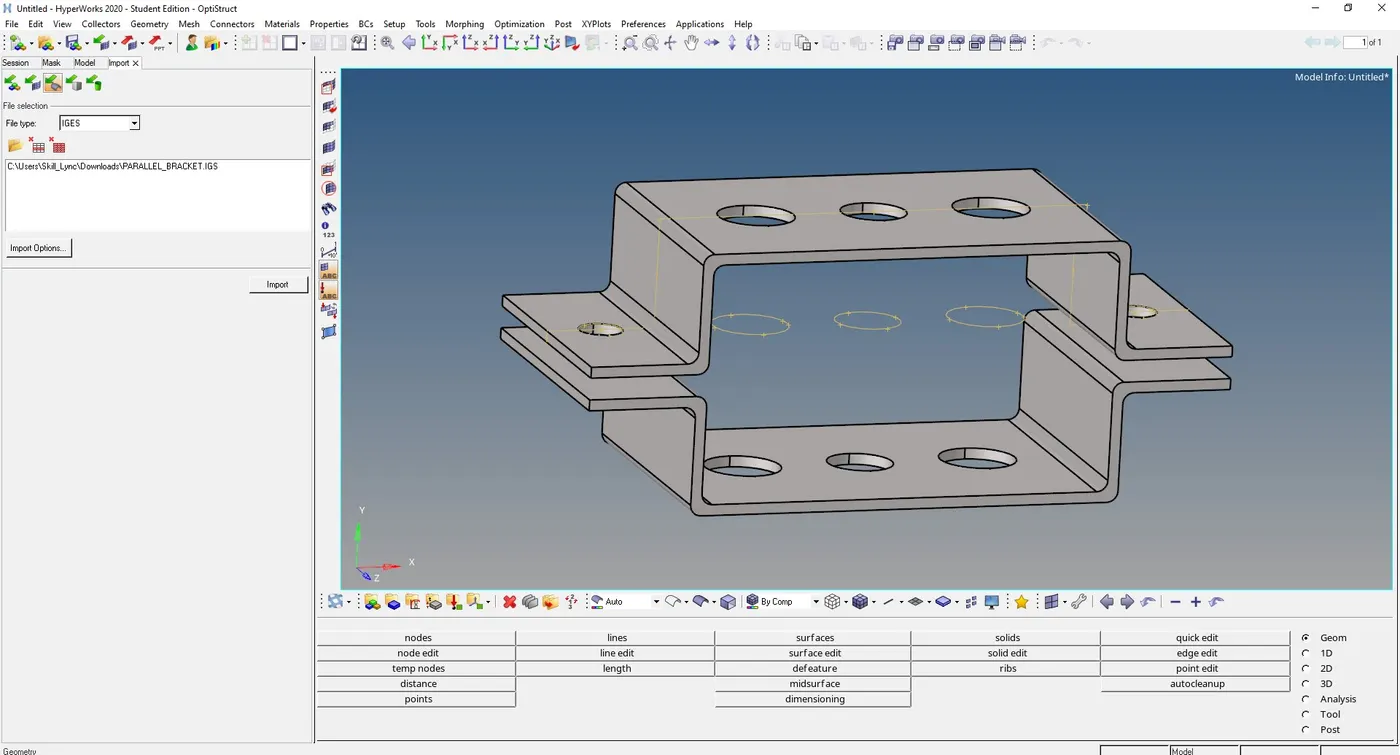
1) First import the given IGES file using Import geometry option, figure below shows the CAD model given.
2 ) Extraction of mid-surface
In order to represent the 3D model as shell elements, we need to extract mid-surface.
Now we need to extract mid-surface of the component and mesh the mid-surface with 2D elements and apply thickness to the component.
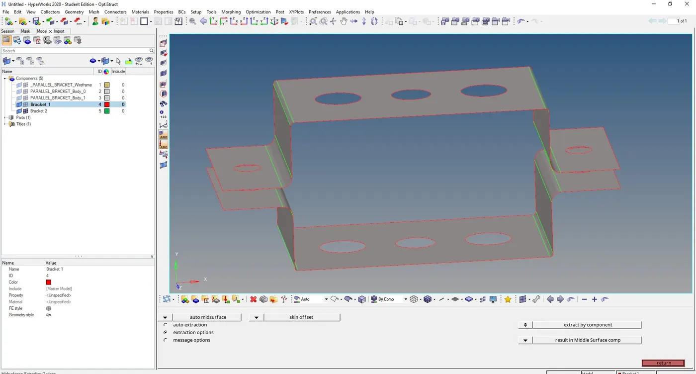
In order to extract mid-surface go to, Geometry -> midsurface, and select the extraction option as skin offset in order to capture the fillets properly,
and choose auto-extraction option and select the top and bottom surfaces to extract mid-surface.
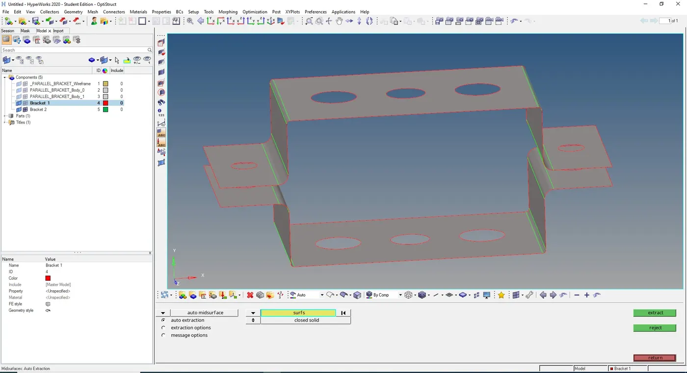
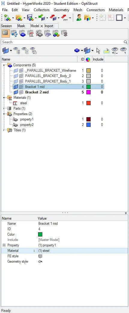
3) we need to rename the mid-surface by right-click on the respective mid, and we need to apply material and properties to the mid-surface created.
To create material, properties right click on the model window and go to Create -> Material/Properties
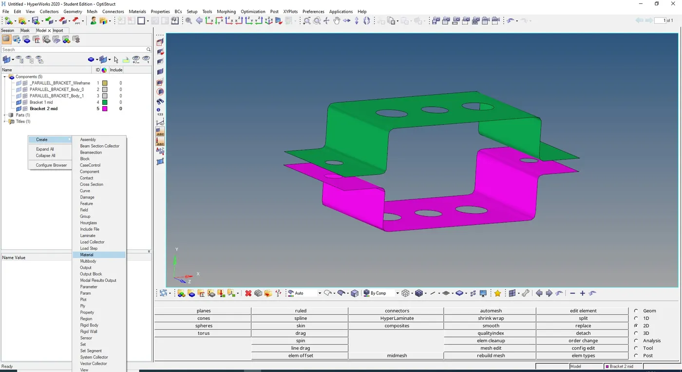
as shown in the image below two different properties and material is created as the two brackets have different thickness.
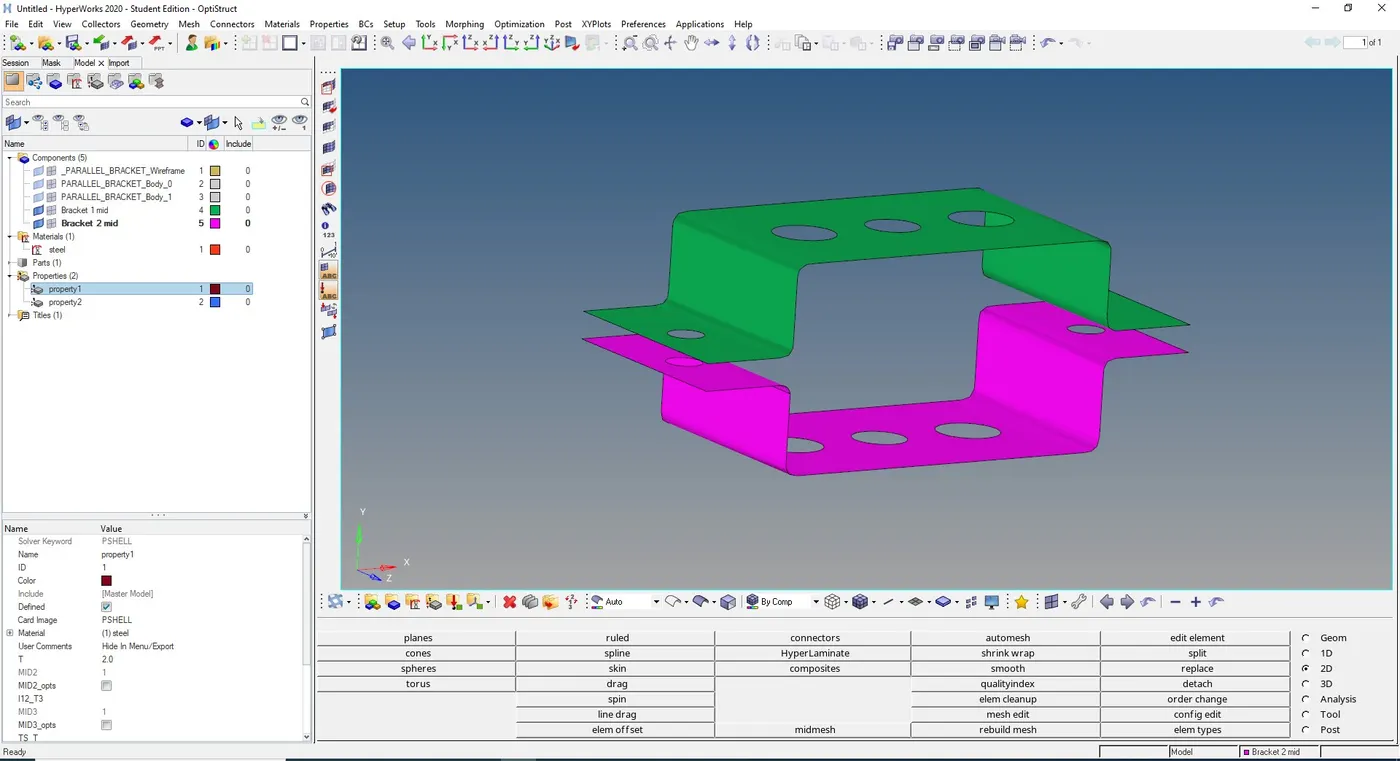
now we assign property and material to the respective mid-surface created. by right-click on the respective mid-surface

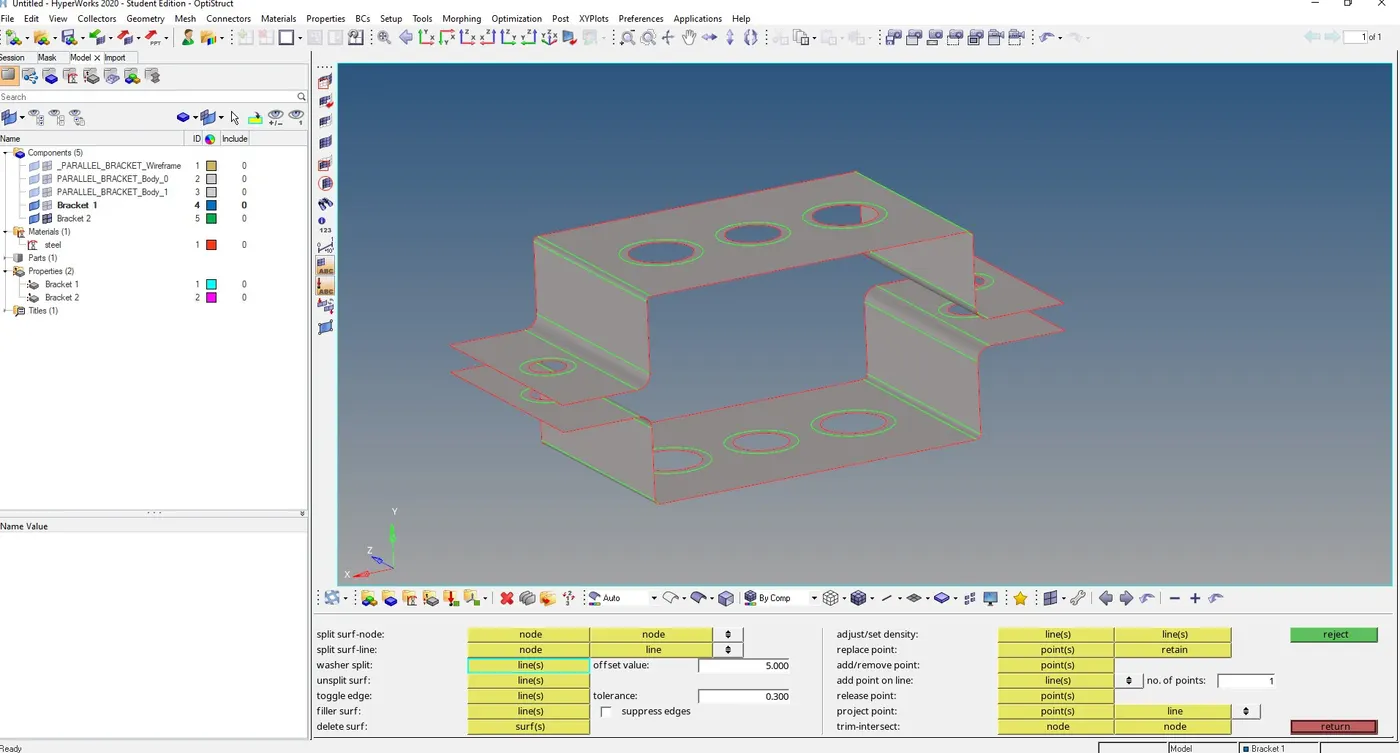
3) we can create washer split around the holes in order to represent high stress concentration region likes hole edges with quad elements.
go to Geometry -> Quick edit- > Washer splits , you can give offset value and click on the hole edges to create washer split around the holes.
4) Creation of 2D Mesh on the mid-surface
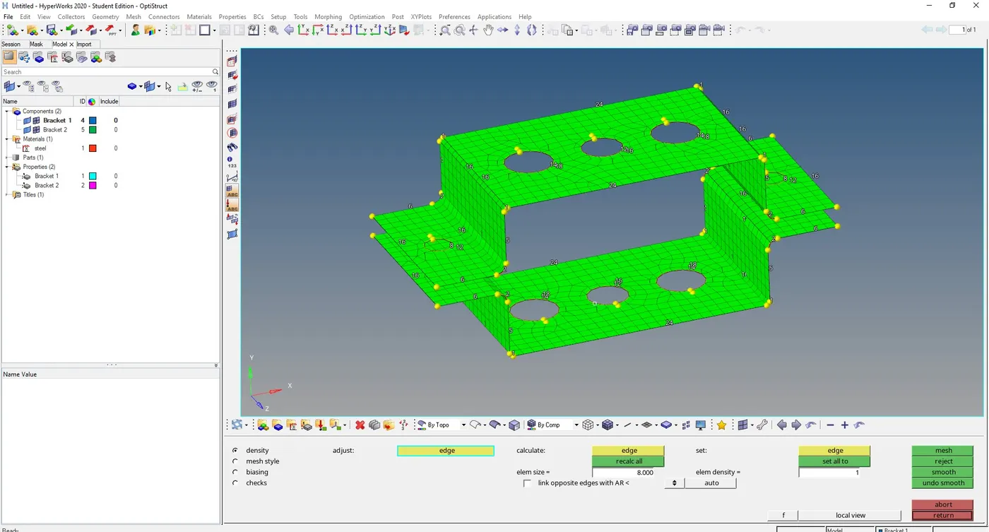
To create Mesh on the mid-surface go to 2D -> Automesh, choose the element size and type of elements and select the surfaces with shift + left mouse box selection and click on mesh
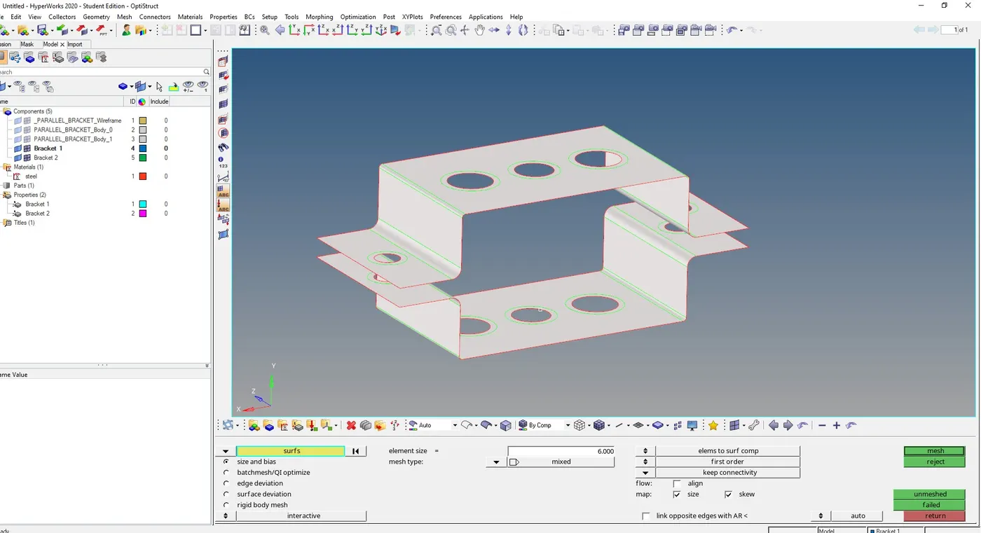
thus 2D mesh is deployed on the mid-surface
- Creation of 1D Elements
5) Creation of RBE2 / RBE3 Elements
First, we need to create RBE2/ RBE3 link around the holes in order to rigidised the holes with respective degrees of freedom,
go to 1D -> rigids/ RBE3 (For creating RBE2 we need to select rigids )
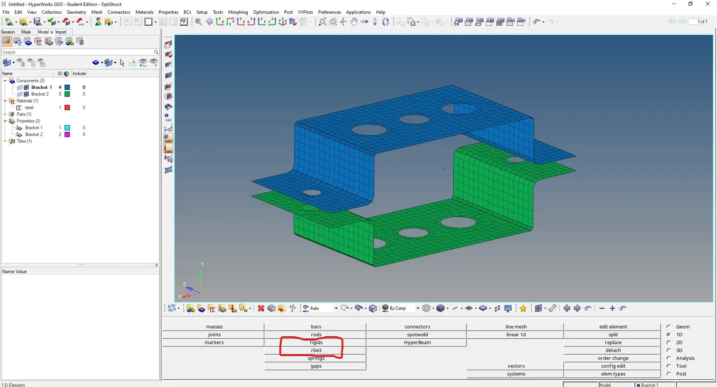
select the nodes around the holes that we need to rigidise ( you can select the nodes by path option in order to select easily) and apply required degree of freedom(d.o.f) and click on create.
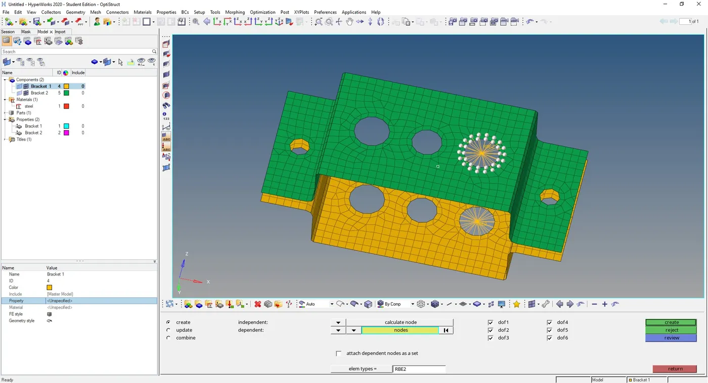
6 ) Creation of Rod element
Now we have to deploy Rod element between RBE2 links, go to 1D -> rods -> create , and select the nodes which we want to deploy connections and click create
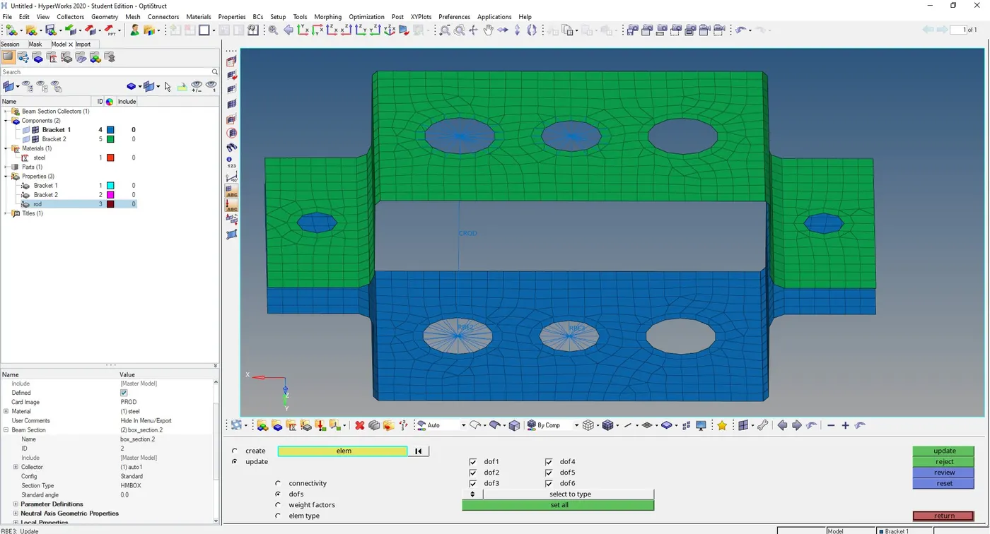
and we need to add property to the rod element.
- Assigning cross-section to the rod element
Go to Hyperbeam view from task bar, right click -> create -> standard section -> hypermesh -> thin walled walls and add dimensions a, b, and tickness as given
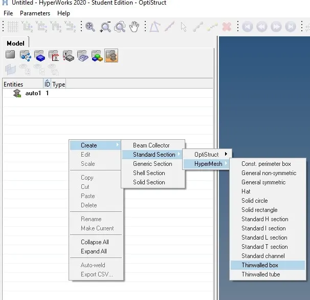
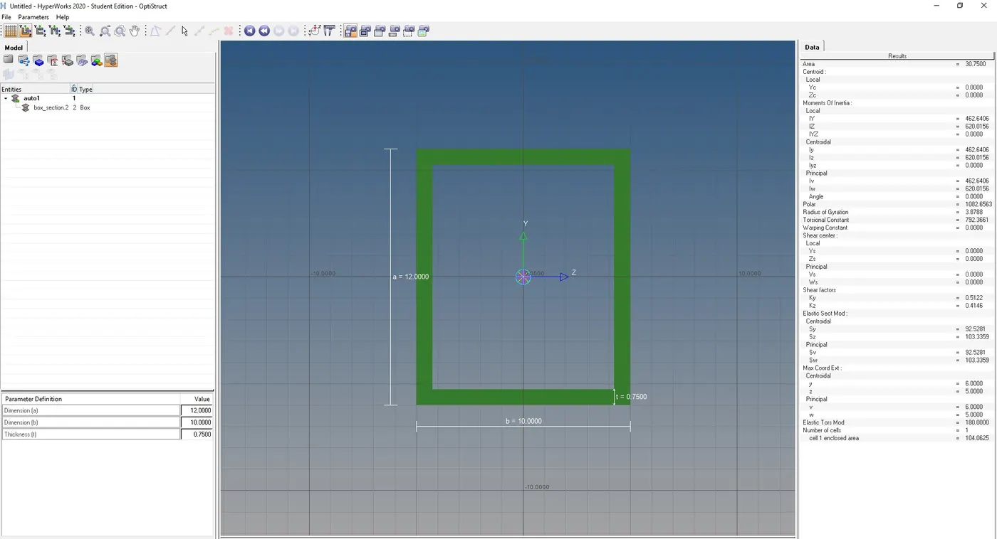
then we have to create a property for rod element, go to Model view then right- click -> create -> property and rename it as rod, select card image as prod, and assign the cross section as box section created for rod.
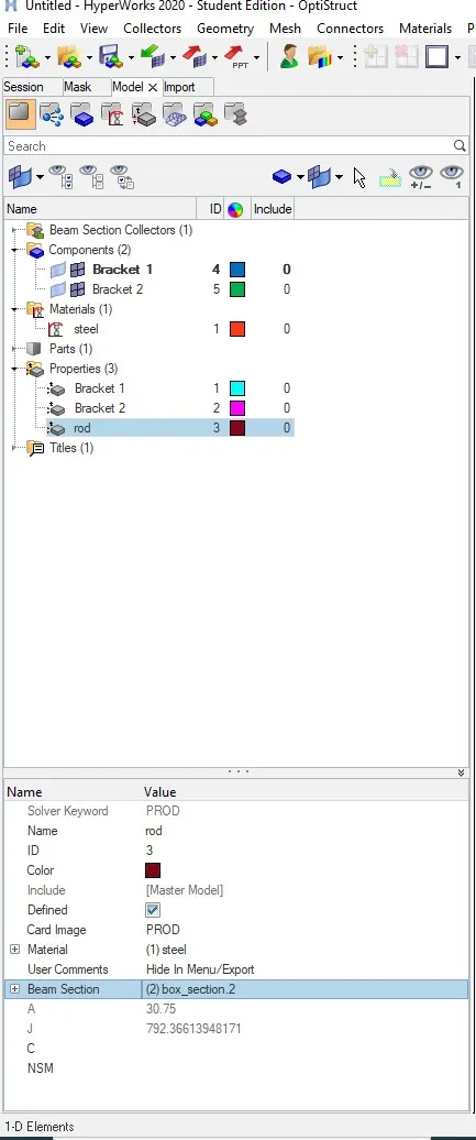
then we need to assign the cross section and property to the rod element and update
7) Creation of Beam and Bar element
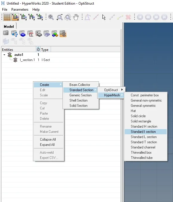
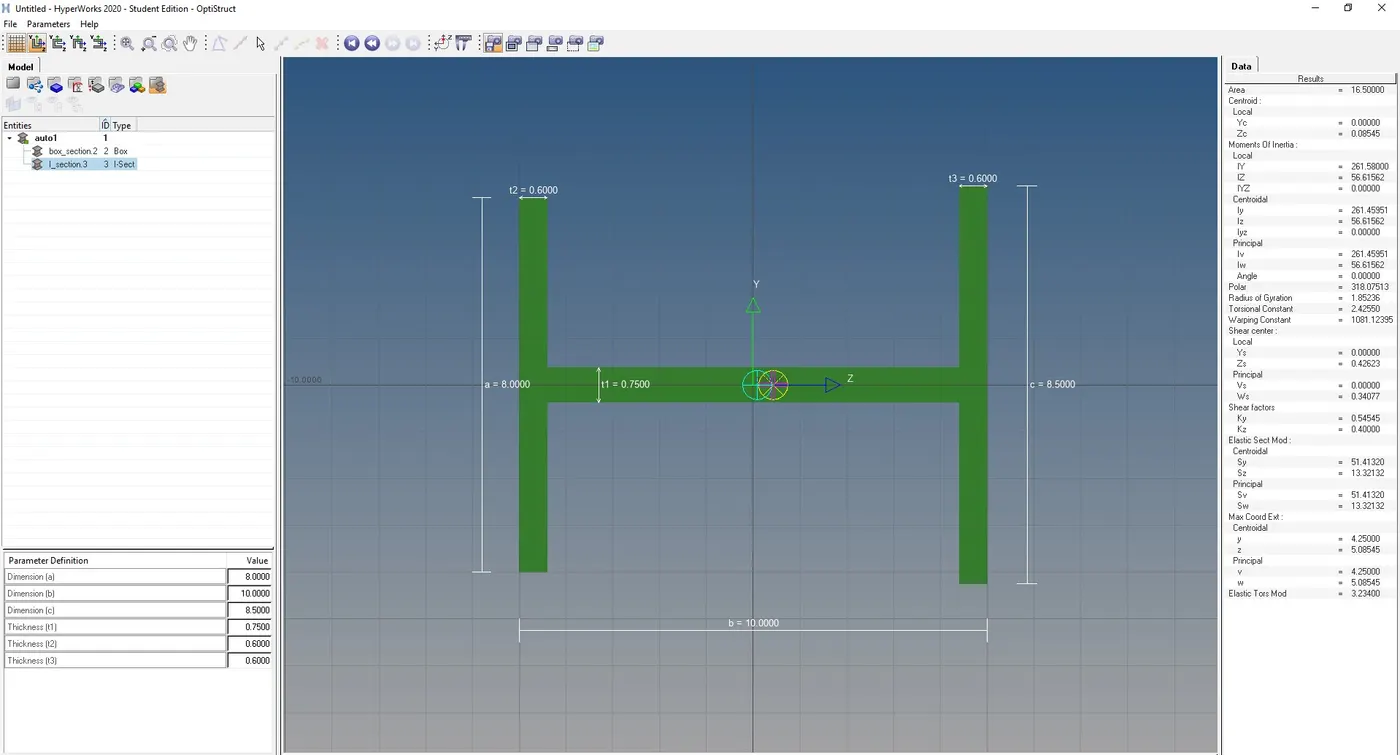
First we need to create cross section( I- section ) for Beam element, Go to Hyperbeam view from task bar, right click -> create -> standard section -> hypermesh -> standard I section
and input values
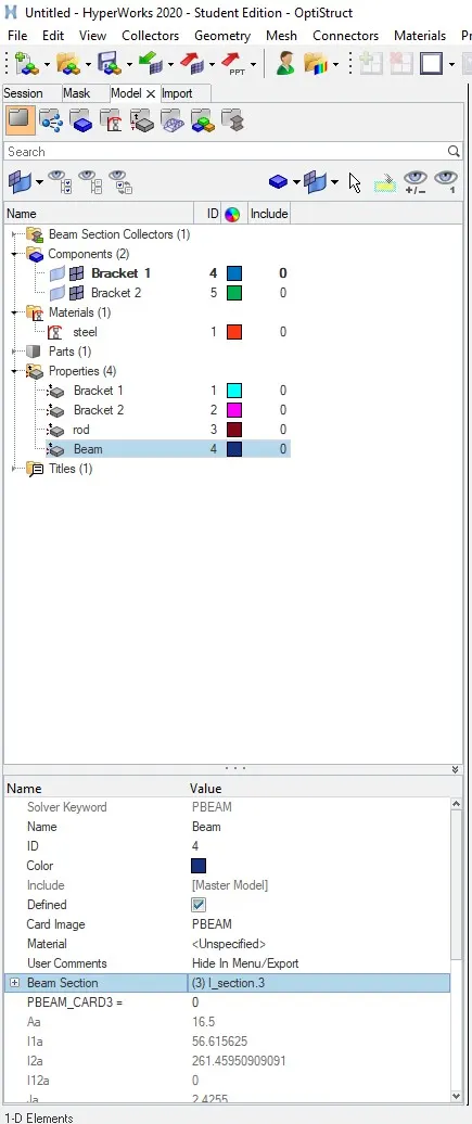
also we need to create a Beam property in model view,
go to Model view then right- click -> create -> property and rename it as beam, select card image as pbeam, and assign the cross section as I- section created for rod.
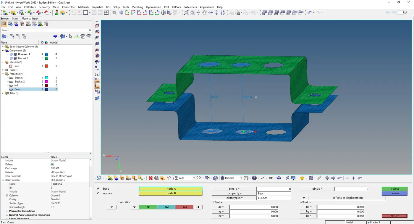
Then we need to create a beam element, go to 1D -> Bars -> Select the Element type as CBEAM, also assign the property we created earlier for beam, and select the nodes where we want to deploy connections and select nodes N1, N2, N3 in order to select the plane.
- Bar Element
Like wise we can create bar element , select the element type as CBAR, also we need to create a CROSS section for bar element. commands are shown in image below
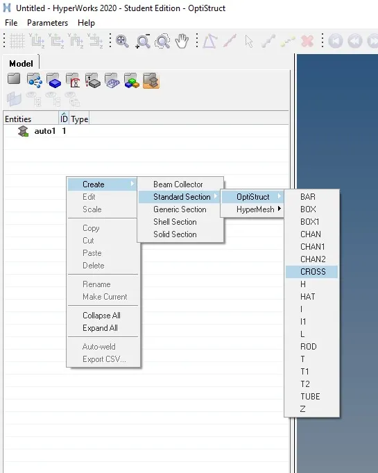
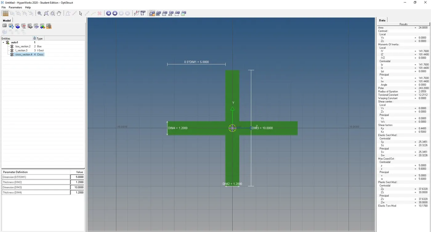
and we need to create a bar property in the Model view and assign CROSS-Section to it. and we add the property to bar element
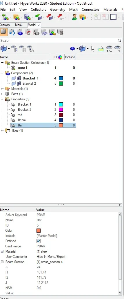
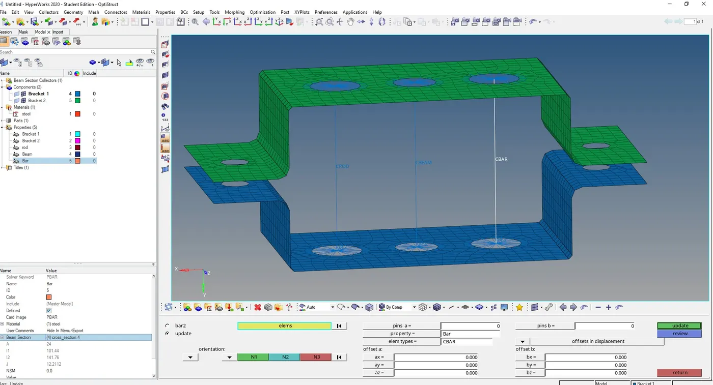
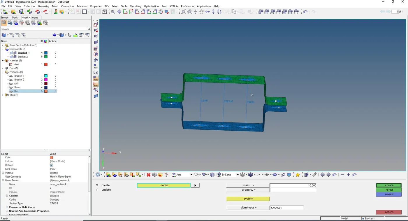
Applying Mass of maginute 10
Go to ID -> masses -> enter the magnitude as 10 and element type as CMASS1, select the nodes where we want to apply mass and select create
Creating Spring element between two brackets
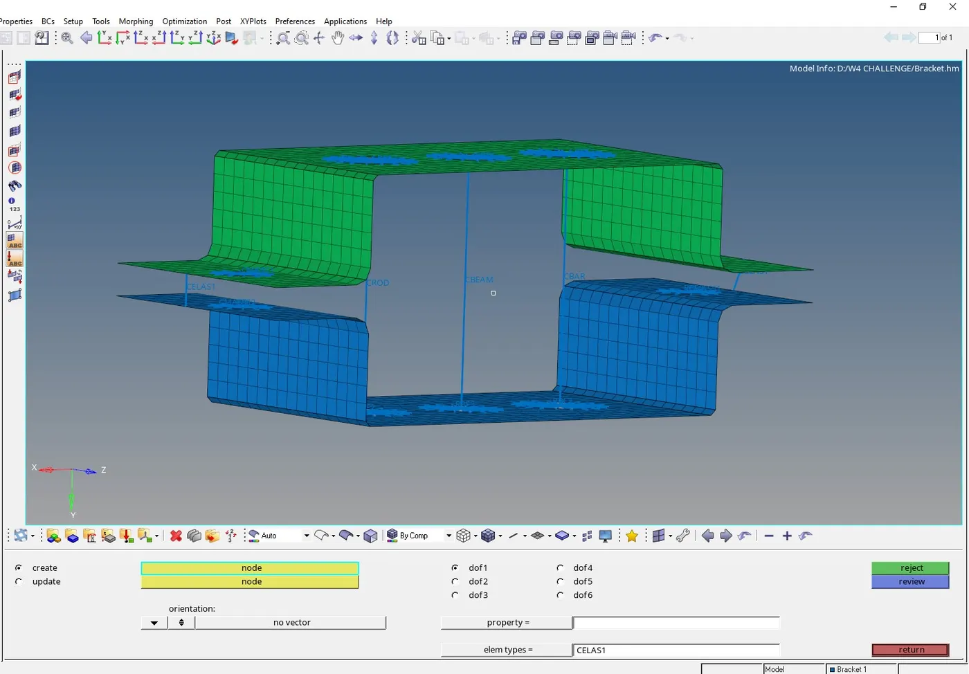
Go to 1D -> springs -> select the nodes where we want to create springs connections between and select element type as CELAS1
Solid Representation of 1D Elements
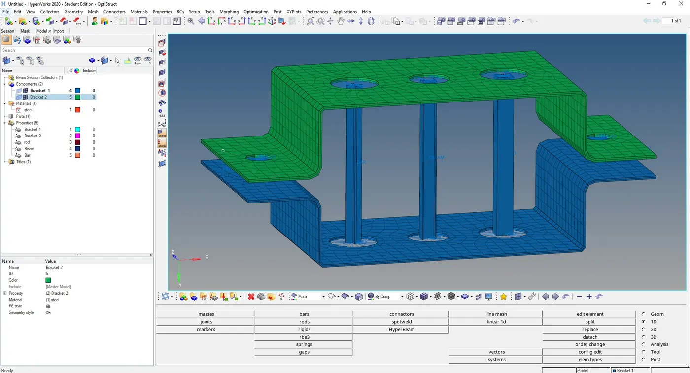
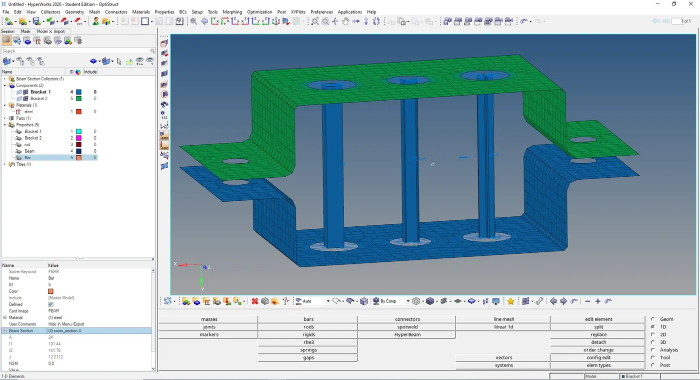
In order to represent the 1D elements created as solids select 1D transalationand detailed element representation
Conclusion
- Extracted the mid-surface for the given component and Created a Mesh on the mid-surface
- Deployed suitable 1D Element ( RBE2, RBE3, ROD, BAR, BEAM , MASS, SPRING etc ) to the respective places.
- Assigned Cross-section and property to the 1D elements
- Created Solid representations of 1D Element.
- Figure given below shows the final output of the component